Characteristics and underlying physics of ionic wind in dc corona discharge under different polarities
Zhang Tongkai2, Zhang Yu3, Ji Qizheng3, Li Ben1, †, Ouyang Jiting2, ‡
National Key Laboratory of Mechatronic Engineering and Control, School of Mechatronical Engineering, Beijing Institute of Technology, Beijing 100081, China
School of Physics, Beijing Institute of Technology, Beijing 100081, China
Beijing Orient Institute of Measurement and Test, Beijing 100094, China


† Corresponding author. E-mail: liben0316@163.com jtouyang@bit.edu.cn

Abstract

During a dc corona discharge, the ions’ momentum will be transferred to the surrounding neutral molecules, inducing an ionic wind. The characteristics of corona discharge and the induced ionic wind are investigated experimentally and numerically under different polarities using a needle-to-ring electrode configuration. The morphology and mechanism of corona discharge, as well as the characteristics and mechanism of the ionic wind, are different when the needle serves as cathode or anode. Under the different polarities of the applied voltage, the ionic wind velocity has a linear relation with the overvoltage. The ionic wind is stronger but has a smaller active region for positive corona compared to that for negative corona under a similar condition. The involved physics are analyzed by theoretical deduction as well as simulation using a fluid model. The ionic wind of negative corona is mainly affected by negative ions. The discharge channel has a dispersed feature due to the dispersed field, and therefore the ionic wind has a larger active area. The ionic wind of positive corona is mainly affected by positive ions. The discharge develops in streamer mode, leading to a stronger ionic wind but a lower active area.

1. Introduction

A corona discharge is a self-sustained discharge that occurs in the vicinity of electrodes with smaller curvature radii.[1] It is often produced by applying high voltages on needle, wire, or tip electrodes. Because of the geometric effect, the electric field in the space presents remarkable non-uniformity and varies with the distance to the active electrode. During the corona discharge, ions are produced from the ionization process and accelerated by the field. The ions with the same polarity as the active electrode drift towards the ground electrode and transfer momentum to the surrounding neutral molecules. The induced fluid movement of all of the particles is so called ionic wind.

Benefiting from non-mechanical components, micro scales, and low costs, this electro-hydrodynamic (EHD) airflow has shown its great potential in applications such as ionizing blower,[2] thermal cooling,[3,4] and recently the flow control.[5,6] It is worth noting that recently Xu et al. reported a powered flight of an aeroplane whose propulsion is based on ionic wind induced by corona discharge.[7] Consequently, various investigations have been carried out on its performance.[810] Moreau et al. made a series of measurements on the velocity of ionic wind.[11,12] In their experiments, the corona discharge produced an ionic wind with a velocity up to 10 m/s under the discharge power of several mW. The behaviors of the ionic wind induced along the flat plate were also visualized by particle imaging velocimetry.[13] It was confirmed that the ionic wind has a great influence on the properties of surrounding airflow and provides an efficient drag reduction. In Kawamoto’s works, the influence of ionic wind was measured by the deformation of water surface. The calculated EHD force is on the order of and its active area has a radius of 5–8 mm.[14,15] Laroussi et al. provided an ionic wind generator based on positive corona by multi-electrodes, though the wind velocity could only reach 2 m/s.[2]

Theoretical and numerical investigations have also been carried out on the ionic wind.[1620] Drews et al. established a theoretical model that describes the different characteristics of ionic winds in dc corona and ac corona.[21] The EHD process was considered using the momentum-transfer equation, flow continuity equation, and Navier–Stokes equation. Dau et al. simulated the EHD flow of an ionic wind device that includes two pin electrodes generating positive and negative corona respectively and generates nearly neutral wind flow using programmable open source OpenFOAM.[22] Most recently, Chen et al. presented a good understand on the ionic wind of negative corona by investigating its time-resolved and averaged characteristics in simulation and also studies the effect of dc voltage polarity on ionic wind experimentally for cooling purpose.[23,24] These works, to some degree, imply that the ionic wind phenomenon depends on the discharge polarity and regime, but the underlying physical mechanisms have not yet become clear. In particular, the ion dynamics and field distribution in negative and positive corona, which may lead to different discharge regimes or characteristics of ionic wind, need further study.

In this paper, we present the experimental and numerical investigation on the ionic wind induced in dc corona discharge. The electrical and mechanical characteristics are measured and compared under different polarities of the applied voltage. By using a fluid model, the development of discharge, as well as the generation of the EHD process is analyzed in detail. A theoretical consideration is made to explain the mechanisms of the ionic wind and the effect of the voltage polarities.

2. Experimental setup

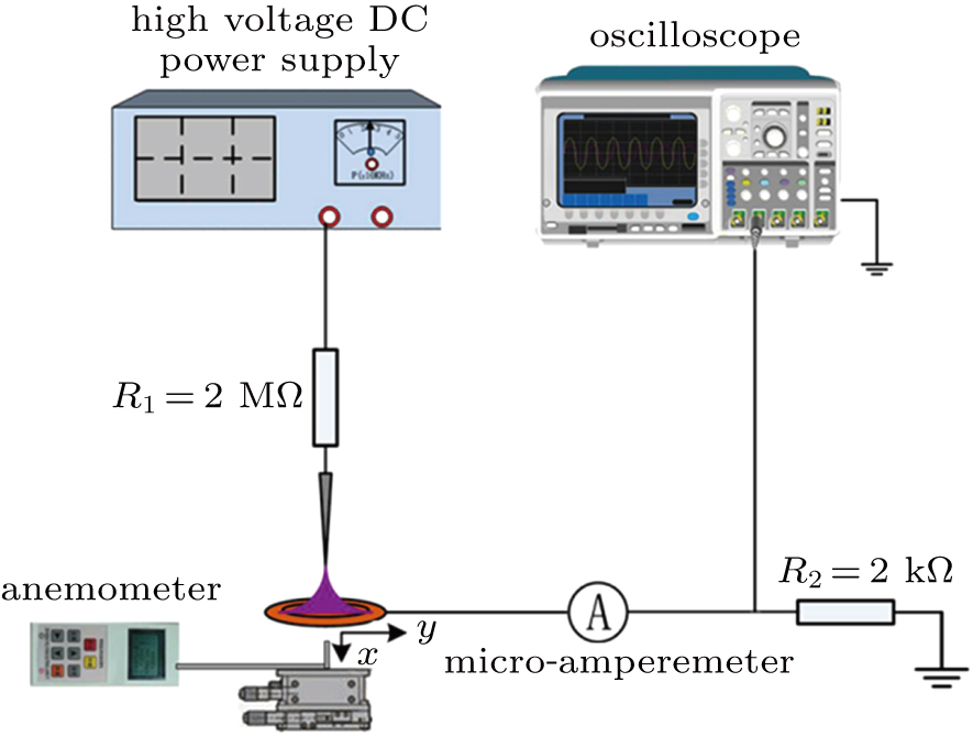
The experimental setup is schematically illustrated in Fig. 1. A needle made of stainless steel, with its tip radius of , is used as the active electrode and is connected to a high-voltage dc power supply (DF1803 A, −20 kV to 20 kV) through a ballast resistance . A copper ring electrode, with an inner radius of 30 mm and an outer radius of 50 mm, is grounded through a sampling resistor . The discharge gap d between the electrodes is adjustable from 0 to 30 mm. The applied voltage Vs can be directly read from the power supply while the averaged discharge current Id is measured by a micro-amperemeter (SWB-IV, with the precision of ). The current waveforms are monitored by the voltage drop across the sampling resistance using a digital oscilloscope (Tektronix TDS-3052) through a voltage probe (T5100), as . The velocity of the ionic wind is measured by an anemometer (with the precision of 0.1 m/s) connected with a Pitot tube downstream the discharge part. The Pitot tube, with an inner diameter of 1.0 mm and an outer diameter of 1.2 mm, is made of glass to avoid interaction with the discharge. The location of the tube is controlled by a micro-displacement positioning platform in experiments.

Fig. 1. Schematic of the experimental setup.
3. Experimental results

The corona discharge in the present configuration turns on when the inception voltage Vc is reached and then the ionic wind with the magnitude of m/s can be measured downstream the discharge part. The following experiment is conducted in ambient air with the temperature of 25 °C and the relative humidity of 30%.

3.1. Negative polarity

During the negative corona, the development of discharge can be generally divided into three stages, as shown in Fig. 2(a). The corresponding discharge images in the sequence of current increasing under d = 5 mm are shown in Fig. 2(b). Stage 1 is the Townsend stage, in which the discharge sustains weakly but stably with a sub- current. Stage 2 is the Trichel pulse stage, where self-sustained and highly repeatable pulses appear in the current waveforms. Finally, the discharge will transit to stage 3, the stable glow stage, and show the typical normal glow morphology, i.e., negative glow (NG), Faraday dark space (FDS), and positive column (PC). Once the applied voltage and hence the local electric field are high enough, a spark will bridge the gas gap. The development of negative corona has been widely discussed in previous works.[25,26] The noticeable thing is that the negative corona shows a diffused-like morphology. The discharge part expands gradually and the light emission gets stronger with the increasing current.

Fig. 2. (a) The VI characteristics of negative corona at different d and (b) the corresponding discharge images in the sequence of current increasing under d = 5 mm.

The measurements of the ionic wind velocity are made at x = 5 mm and y = 0 mm downstream the discharge part. The results are summarized in Fig. 3. In the present negative corona discharge experiment, the induced ionic wind velocity is about several m/s, which is in accordance with previous works.[2,1115] As can be seen, the averaged velocity follows a linear relation with the over voltage (or the difference between the applied voltage and the inception voltage, ) at each given gas gap, as . The slope k decreases with d. Its value reduces from 1.03 m/(s kV) to 0.25 m/(s kV) when d increases from 10 mm to 30 mm. The transition of discharge stages has little influence on this tendency.

Fig. 3. Ionic wind velocity in negative corona at different d measured at x = 5 mm downstream the discharge part.

Some previous studies also reported the investigations on the VI and vV characters, such as Figs. 2 and 3, under other electrode configurations and obtained similar results, which demonstrate the correctness and universality of the results obtained here.[27]

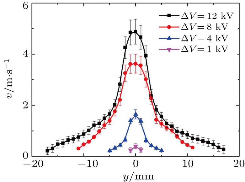
Furthermore, the profiles of the wind velocity are obtained spatially by adjusting the location of the tube using the positioning platform. Figure 4 depicts the distribution of the wind velocity measured at x = 5 mm under d = 20 mm with varying y and the overvoltage . The inception voltage Vc is 6 kV. The ionic wind velocity under the given conditions keeps a relatively large value ( ) at the central part and decreases gradually with the distance from the center. The shape of the wind profile is independent of the varying overvoltage, but the radius of the active area increases significantly at larger . As shown in Fig. 4, it expands from 1 mm to 17 mm when the overvoltage increases from 1 kV to 12 kV.

Fig. 4. Profiles of ionic wind velocity in negative corona at different . The inception voltage Vc is 6 kV.
3.2. Positive polarity

The characteristics of positive corona are quite different from those of the negative one as previously reported.[1,2] Generally, the current waveforms of positive corona appear as a series of irregular narrow pulses instead of highly repetitive pulses (or Trichel pulses) in negative corona. The average current increases rapidly with the increasing applied voltage until sparks in experiment, as shown in Fig. 5(a). Unlike the diffused-like negative corona, the positive corona propagates mainly along the central axis. As illustrated in Fig. 5(b), the positive corona firstly appears ahead of the needle tip and then forms a straight discharge channel. Compared with that excited by negative polarity, the positive corona has a relatively stronger intensity at the central part but a much narrow discharge channel.

Fig. 5. (a) The VI characteristics of positive corona at different d and (b) the corresponding discharge images in the sequence of current increasing under d = 20 mm.

The v plot of the positive ionic wind is shown in Fig. 6 and also follows the linear relation. The difference is that the slope of the v plot of the positive ionic wind is much larger than that of the negative one. It implies that the positive corona could produce a stronger ionic wind at the central part compared with the negative corona under the same overvoltage. For example, the induced positive ionic wind is about 5.3 m/s at the central part under d = 20 mm and , which is about 20% higher than that in negative corona under the same conditions.

Fig. 6. Ionic wind velocity in positive corona at different d measured at x = 5 mm downstream the discharge part.

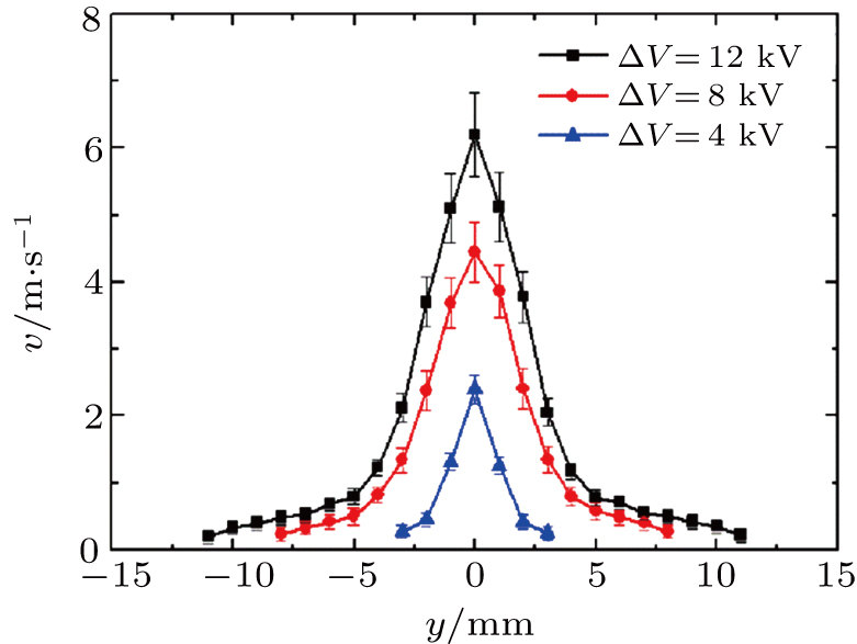
In addition, the profile of the ionic wind in positive corona is quite different from that of the negative ionic wind, as shown in Fig. 7. The inception voltage Vc is 7 kV. The wind velocity also reaches its maximum at the central part but decreases sharply with the increasing radial distance y. Under in Fig. 7, the velocity is about 6.3 m/s at center but reduces to no more than 0.7 m/s near y = 5 mm. The active area of the positive ionic wind is only about 10 mm, which is about 35% smaller than that of the negative one. The active region of the positive ionic wind always has a smaller area under each of the given conditions.

Fig. 7. Profiles of ionic wind velocity in positive corona at different . The inception voltage Vc is 7 kV.
4. Numerical results

The EHD generation process of the ionic wind in both negative and positive corona is also investigated numerically using a 2D axis-symmetric fluid model. Major particles (N2, O2, , , , electrons, etc.) in atmospheric air discharge are considered. The interaction among these particles is described by importing cross-section files or using simplified reaction rate coefficients from Refs. [28]–[30]. The particle behaviors and the electric field distribution are calculated by solving the coupled continuity equations of species and Poisson’s equation, which is similar to the previous works.[2830]

4.1. Negative polarity

Considering that the negative ionic wind in applications often works under the voltage condition of the Trichel pulse stage, the simulation is conducted in the pulsed stage mainly. We here start with the spatiotemporal development of the negative corona discharge. In atmospheric air discharge, the density of is remarkably larger than that of the other positive ion species while the density of is larger than that of the other negative ion species, so the developments of these two kinds of ion clouds are mainly concerned, as shown in Figs. 8(b) and 9, respectively. A needle-to-plate electrode configuration with the electrode distance d = 3.3 mm is employed. The simulation area is within x = 0–3.5 mm and y = 0–5 mm, and the partial area of y = 0–2.5 mm is presented. The moment of each sub-image is denoted on the Trichel pulse in Fig. 8(a), and the ion density is presented in form of logarithm.

Fig. 8. (a) Waveform of Trichel pulse and (b) spatiotemporal development of density during the pulse in negative corona discharge under a needle-to-plate electrode configuration. The moment of each sub-image in the development sequence is indicated in image (a).

In Fig. 8(b), only a low density of 109 cm−3 concentrates in a small area around the needle tip when the pulse just starts at 84 ns. With the pulse rising quickly, the density increases generally to 1010 cm−3 and it is up to 1012 cm−3 near the needle tip (see the case of 102 ns). In the meantime, the area of high density is enlarged and the ion clouds near the needle cathode start to shrink towards it, indicating that the cathode ion sheath is gradually formed. At the pulse peak of 137 ns, the ion cloud near the needle cathode reaches its maximum density of cm−3 and completely surrounds the needle tip, indicating that the cathode ion sheath is completely formed. In the meantime, an density up to 1011 cm−3 is also developed near the grounded electrode, corresponding to the positive column region. Afterwards, the ion density starts to decay with the current falling (see the case of 261 ns), but there is still an density of 109 cm−3 left near the needle cathode at the end of current pulse (see the case of 522 ns). This result illustrates that the Trichel pulse is in essence a process of positive ions concentrating first and then diffusing. The cathode ion sheath forms during the rising edge of the pulse while is destructed during the falling edge of the pulse.

In Fig. 9, at the beginning of the Trichel pulse, the density also starts to accumulate near the needle cathode but downstream the cloud comparing with the case of 84 ns in Fig. 8(b). As the pulse rises, the density increases and reaches the maximum of 1011 cm−3 (see the cases of 102 ns and 137 ns), lower than the density by an order. However, the density decreases relatively slow so as to exceed the density with the discharge decay (216 ns). At the end of the pulse, there is still a density of 1011 cm−3 left in the whole discharge channel (522 ns).

Fig. 9. Spatiotemporal development of density during the Trichel pulse in negative corona discharge under a needle-to-plate electrode configuration. The moment of each sub-image in the development sequence is indicated in Fig. 8(a).

As can be seen in Figs. 8 and 9, the positive ions increase faster than the negative ions and form an ion sheath near the cathode, which is the main reason for the formation of the Trichel pulsed discharge. Out of the ion sheath region, the negative ions are formed and drift towards the ground electrode along the applied field, which should be the main reason for the formation of ionic wind of negative corona. Afterwards, the negative ions exceed the positive ions and have a large density left in the discharge channel, resulting in the extinguishment of the discharge.

Physically, the generation of the ionic wind is related to the spatiotemporal development of ion distribution and is described by the Navier–Stokes equation

where ρ is the air density, P is the ambient pressure, is the wind velocity, is the viscous stress tensor associated with the collisions between neutral particles, and E is the electric field strength. f represents the external force on fluid (or the EHD force), which is calculated as
where the subscript i and e represent ions and electrons, respectively. The value of the sign function equals to 1 when the drift of particles is in the direction of the ionic wind, and equals to −1 otherwise.

Equation (1) indicates that the force f(E) is the EHD source of the ion movement and therefore determines the generation of the ionic wind. Thus, we investigate the spatiotemporal distribution of the EHD force f(E) during the pulsed discharge under a needle-to-ring electrode configuration with d = 10 mm. The simulation area is within x = 0–15 mm and y = 0–5 mm. The normalized results are shown in Fig. 10(b) and the corresponding moments are marked on the waveform in Fig. 10(a). At the pulse initial time, the density of ions and therefore the value of EHD force are quite low in the discharge channel (t = 84 ns). As the pulse rises, f(E) has a negative value only at the vicinity of the tip, but keeps a positive value at the other part of the channel (t = 137 ns). On the whole, it has an accelerating effect on the drift of negative ions, thus forming the ionic wind toward the grounded side. During the pulse decay, although the value of f(E) reduces due to the decrease of the local field and ion density, the EHD force still motivates the negative ion flow (t = 216 ns). Finally in the pulse interval, the EHD force keeps a very low value in most parts of the channel due to the negative ions left in the applied field (t = 522 ns).

Fig. 10. Numerical results of negative corona under a needle-to-ring electrode configuration: (a) the simulated Trichel pulse, (b) the spatiotemporal distribution of the normalized EHD force f(E), the data is normalized by 1.26 N/cm3.

The distribution of the EHD force in the stable Townsend stage or in the glow stage is similar to that at the pulse initial time (see the case of t = 84 ns) or the pulse peak (see the case of t = 137 ns), respectively. Here, the description would not be repeated any more.

Then the time-averaged velocity of the ionic wind can be calculated by solving Eq. (1) and then averaged over several Trichel pulse periodTpulse as

For negative corona, the parameter n is chosen as 10 in simulation, or ; for positive corona, the current pulse has no periodicity, but is still employed, which is a long-enough period including many pulses to reach a steady gas flow and to do the averaging calculation. Similarly, the averaged velocity in the stable Townsend and glow stages is averaged over a relatively long period to reach a steady gas flow (i.e., )
The results of Eqs. (3) and (4) at x = 5 mm downstream the grounded electrode at the central part are summarized in Fig. 11. The simulated results are in good agreement with the experimental results that the ionic wind velocity of negative corona is in order of m/s and increases linearly with the overvoltage. The calculated velocity is a little larger because the influence of airflow viscosity is not considered in the present model.

Fig. 11. Calculated time-averaged velocity of ionic wind in negative corona.
4.2. Positive polarity

The EHD process in positive corona is also investigated using the present model. The discharge conditions are similar to those in the negative corona model and in experiment.

The positive corona propagates in streamer mode as successive positive ion clouds move towards the grounded electrode, which has been discussed in detail in classical works.[1] Each propagating cloud contributes a narrow pulse in the waveforms. Figure 12(a) shows an exemplary pulse of positive corona discharge under the needle-to-plate electrode configuration with the electrode distance d = 3.3 mm. Figure 12(b) gives the spatiotemporal development of density corresponding to the moments marked on the pulse. The simulation area is within x = 0–3.5 mm and y = 0–5 mm, and the partial area of y = 0–2.5 mm is presented. The high ion density region starts from near the needle anode (185 ns) and propagates quickly towards the grounded electrode (205 ns) as the pulse rises. The difference from the negative corona case is that the maximum density always sits in front of the head of ionization. The ion density reaches up to 1013 cm−3, which constricts electrons into the discharge channel and meanwhile promotes the discharge developing towards the grounded electrode. The positive ion cloud reaches the grounded electrode at the pulse peak (215 ns) and then is absorbed by the grounded electrode, resulting in the discharge decay. In general, compared to the negative corona, the positive corona develops faster and has higher local positive ion density.

Fig. 12. (a) Waveform of positive corona discharge pulse and (b) spatiotemporal development of density during the pulse under a needle-to-plate electrode configuration. The moment of each sub-image in the development sequence is indicated in image (a).

In the positive corona, due to the fact that electrons drift towards the needle anode, the negative ions, formed by neutral molecules absorbing electrons, generally have nothing to do with either the pulsed discharge or the formation of ionic wind. Consequently, the distribution of the EHD force varies with the movement of the positive clouds. The spatiotemporal development of the normalized EHD force is calculated using the method in Eq. (2) and is plotted in Fig. 13(b). The needle-to-ring electrode configuration with d = 10 mm is employed. The simulation area is within x = 0–15 mm and y = 0–5 mm. The moments are marked on the pulse in Fig. 13(a).

Fig. 13. Numerical results of positive corona under a needle-to-ring electrode configuration: (a) a single discharge pulse of positive corona, (b) the spatiotemporal distribution of the normalized EHD force f(E), the data is normalized by 2.83 N/cm3.

At the beginning of the pulse (185 ns), the EHD force accelerates the flow mainly at the vicinity of the needle anode, where the positive cloud is gradually formed. Around the pulse peak, the positive cloud propagates to the grounded side and is strengthened by ionization (or the electron avalanches) through the discharge path. Therefore, the EHD force has a positive effect on the generation of the positive ionic wind in the most part of the discharge gap (215 ns). Then, the discharge current falls back and the positive cloud is absorbed by the grounded electrode. As a result, the force f(E) reduces and distributes mainly around the grounded part (290 ns). The discharge pulses in positive corona are irregular and generally the value of f(E) is positively associated with the pulse current, but the spatiotemporal distribution always follows the tendency described in Fig. 13.

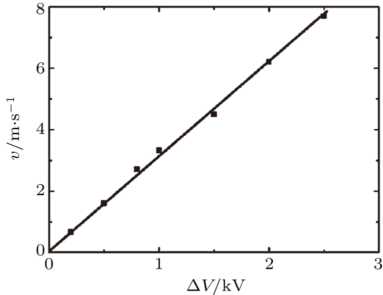
The time-averaged velocity of the ionic wind in positive corona is calculated by the integral of Eq. (4) over a long period. The averaged value at x = 0 and y = 5 mm is shown in Fig. 14, which accords well with the experimental results. The velocity of the ionic wind under positive polarity is proportional to the overvoltage and is stronger than that under negative polarity.

Fig. 14. Calculated time-averaged velocity of ionic wind in positive corona.
5. Discussion

In the dc corona discharge, the electric field is sharply non-uniform due to the geometric effect. Two regions can be distinguished in the inter-electrode space.[11,15,21,31] The ionization region with a size of several millimeters in general locates at the vicinity of the active electrode, where the field is strong and the ionization process (or the electron avalanche) sustains. The second region, which is termed the drift region, locates from the ionization region to the grounded electrode. In the drift region, the field is insufficient to sustain the ionization and the ion drift is driven by the field. The momentum will be transferred to surrounding molecules through collisions, thus forming the ionic wind.

In the negative corona, the produced positive ions from ionization are attracted by the needle cathode and the electrons are driven towards the grounded electrode. In the drift region where the electric field is relatively low, the slow electrons will soon be captured by electron-negative molecules (i.e., O2 in air), forming the negative ions and then momentum transfer happens between negative ions and molecules. The electrons move along the diffused field and therefore the induced electron avalanches are dispersed from each other, as shown in Fig. 15(a). As a result, the negative corona sustains a diffused-like morphology as observed in Fig. 2(b). Then the induced ionic wind in negative corona has a larger active area.

Fig. 15. Discharge mechanism in (a) negative corona and (b) positive corona.

However, the direction of the field is reversed in the positive corona, as shown in Fig. 15(b). The positive ions, created by electron avalanches, drift towards the grounded electrode along the applied field. During the course, they collide with and hence transfer momentum to neutral molecules to form the ionic wind. The electron avalanches are converged towards the needle anode, resulting in that the discharge propagates mainly along the central axis and forms a stronger but narrow discharge channel in streamer mode. The induced ionic wind has a larger velocity at the central part but a much smaller active area than that under negative polarity.

A brief discussion can be made on the relation between the wind velocity v and the overvoltage . The velocity of the induced ionic wind is determined by the EHD force applied on the fluid.[11,21,32] The spatiotemporal distribution of the force has been investigated numerically in Section 4. When the ionic wind is stably sustained, the correlations between the time-averaged force and the overvoltage can be obtained by solving the Gauss’s laws, continuity equation of ions, and electric field equation in the drift region, as follows:

where μ is the mobility of ions. A rough result under 1D approximation has been deduced in previous works[21,32] as
Under the approximation, equation (1) can be further deduced as
Solving the set of Eqs. (7)–(9), the correlation between the wind velocity and the overvoltage can be represented as
This theoretical result is a general result of the EHD process in corona discharge under both negative and positive polarity. It indicates the qualitative correlation that the velocity of the wind is proportional to the overvoltage. However, the exact value of the wind velocity could not be precisely predicted by the 1D approximation. The characteristics of the ionic wind vary with the polarities due to the different discharge mechanisms and the different distributions of the EHD force in negative and positive corona.

6. Conclusion

The characteristics of ionic wind in dc corona discharge are investigated experimentally and numerically using the needle-to-ring configuration. In the present experiment, the averaged velocity and the distribution of the ionic wind are measured and compared under different polarities. The dynamics of the ions and the spatiotemporal distribution of the EHD force during discharges are simulated by a 2D axis-symmetric fluid model. Under negative and positive polarities, the mechanisms of corona and the induced ionic winds are different. The results are summarized as follows.

(I) The velocity of the ionic wind always increases lineally with the overvoltage in both kinds of polarities, but the velocity in the positive corona case increases faster than that in the negative corona case under similar conditions.

(II) The negative corona has a diffused morphology causing an ionic wind with a larger active area but a lower velocity. The positive corona propagated in streamer mode forms a straight discharge channel. The induced ionic wind has a relatively stronger velocity but a much smaller active area under the same overvoltage of negative corona.

(III) The spatiotemporal distribution of EHD force is different during the generation of the ionic wind under different polarities. The EHD force accelerates the negative ions mainly at the grounded side in negative corona discharge. However, in the positive corona, the positive ions are accelerated during their drift in the inter-electrode space.

(IV) The differences of characteristics between negative and positive ionic winds are caused by the different discharge mechanisms. The electron avalanches are dispersed from each other to induce a diffused-like discharge under negative polarity but converged towards the needle electrode, leading to propagation of positive ions and further the streamer mode under positive polarity.

Reference
[1] Raizer Y P 1991 Gas Discharge Physics Berlin Heidelberg Springer-Verlag 324 https://www.springer.com/us/book/9783642647604
[2] Karakas E Begum A Laroussi M 2008 IEEE Trans. Plasma Sci. 36 950 https://doi.org/10.1109/TPS.2008.924401
[3] Go D B Garimella S V Fisher T S Mongia R K 2007 J. Appl. Phys. 102 053302 https://doi.org/10.1063/1.2776164
[4] Yue Y G Hou J P Ai Z L Yang L J Zhang Q G 2006 Plasma Sci. Technol. 8 697 https://doi.org/10.1088/1009-0630/8/6/16
[5] Mestiri R Hadaji R Ben N S 2010 Phys. Plasmas 17 083503 https://doi.org/10.1063/1.3474924
[6] Zhang Y Liu L J Li B Ouyang J T 2016 Plasma Sci. Technol. 18 634 https://doi.org/10.1088/1009-0630/18/6/09
[7] Xu H F He Y O Strobel K L Gilmore C K Kelly S P Hennick C C Sebastian T Woolston M R Perreault D J Barret S R H 2018 Nature 563 532 https://doi.org/10.1038/s41586-018-0707-9
[8] Colas D F Ferret A Pai D Z Lacoste D A Laux C O 2010 J. Appl. Phys. 108 103306 https://doi.org/10.1063/1.3514131
[9] Kiousis K N Moronis A X Fruh W G 2014 Plasma Sci. Technol. 16 363 https://doi.org/10.1088/1009-0630/16/4/11
[10] Qiu W Xia L Yang L Zhang Q Xiao L Chen L 2011 Plasma Sci. Technol. 13 693 https://doi.org/10.1088/1009-0630/13/6/11
[11] Moreau E Touchard G 2008 J. Electrostat. 66 39 https://doi.org/10.1016/j.elstat.2007.08.006
[12] Moreau E Benard N Lan-Sun-Luk J D Chabriat J P 2013 J. Phys. D: Appl. Phys. 46 475204 https://doi.org/10.1088/0022-3727/46/47/475204
[13] Léger L Moreau E Artana G Touchard G 2001 J. Electrostat. 51–52 300 https://doi.org/10.1016/S0304-3886(01)00089-4
[14] Kawamoto H Umezu S 2005 J. Phys. D: Appl. Phys. 38 887 https://doi.org/10.1088/0022-3727/38/6/017
[15] Kawamoto H Yasuda H Umezu S 2006 J. Electrostat. 64 400 https://doi.org/10.1016/j.elstat.2005.10.023
[16] Cagnoni D Agostini F Christen T Parolini N Stevanović I De Falco C 2013 J. Appl. Phys. 114 233301 https://doi.org/10.1063/1.4843823
[17] Li Q Li H F Sun X R Zhang W Y Wang H 2010 High Vol. Engin. 36 2739 https://doi.org/10.13336/j.1003-6520.hve.2010.11.001
[18] Matéo-Vélez J C Degond P Rogier F Séraudie A Thivet F 2008 J. Phys. D: Appl. Phys. 41 035205 https://doi.org/10.1088/0022-3727/41/3/035205
[19] Liu Y Cui X Lu T B Li X B Wang Z G Xiang Y Wang X B 2015 Chin. Phys. B 24 065201 https://doi.org/10.1088/1674-1056/24/6/065201
[20] Qian M Y Yang C Y Chen X C Ni G S Liu S Wang D Z 2015 Chin. Phys. Lett. 32 075202 https://doi.org/10.1088/0256-307X/32/7/075202
[21] Drews A M Cademartiri L Whitesides G M Bishop K J 2013 J. Appl. Phys. 114 143302 https://doi.org/10.1063/1.4824748
[22] Dau V T Dinh T X Terebessy T Bui T T 2016 Sens. Actuators A 244 146 https://doi.org/10.1016/j.sna.2016.03.028
[23] Chen S Nobelen J C P Y Nijdam S 2017 Plasma Source Sci. Technol. 26 095005 https://doi.org/10.1088/1361-6595/aa86b8
[24] Chen S van den Berg R G W Nijdam S 2018 Plasma Source. Sci. Technol. 27 055021 https://doi.org/10.1088/1361-6595/aabd5f
[25] Zhang Y Qin Y Zhao G Ouyang J T 2016 J. Phys. D: Appl. Phys. 49 245206 https://doi.org/10.1088/0022-3727/49/24/245206
[26] Callebaut T Kochetov I Akishev Y Napartovich A Leys C 2004 Plasma Sources Sci. Technol. 13 245 https://doi.org/10.1088/0963-0252/13/2/008
[27] Qiu W Xia L Z Tan X Y Yang L J 2010 IEEE Trans. Plasma Sci. 38 2848 https://doi.org/10.1109/TPS.2010.2060500
[28] Wu F F Liao R J Yang L J Liu X H Wang K Zhou Z 2013 Acta Phys. Sin. 62 348 (in Chinese) https://doi.org/10.7498/aps.62.348
[29] Durán-Olivencia F J Pontiga F Castellanos A 2014 J.Phys. D: Appl. Phys. 47 415203 https://doi.org/10.1088/0022-3727/47/41/415203
[30] Dordizadeh P Adamiak K Castle G P 2015 J. Phys. D: Appl. Phys. 48 415203 https://doi.org/10.1088/0022-3727/48/41/415203
[31] Béquin P Castor K Scholten J 2003 Eur. Phys. J. Appl. Phys. 22 41 https://doi.org/10.1051/epjap:2003006
[32] Zhang Y Liu L J Chen Y Ouyang J T 2015 J. Electrostat. 74 15 https://doi.org/10.1016/j.elstat.2014.12.008