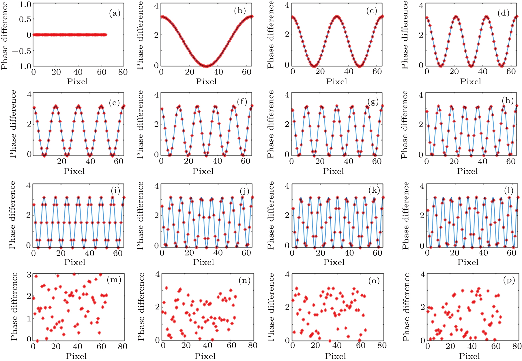
Memory effect evaluation based on transmission matrix calculation
The phase difference profiles along one direction of Fig.

Memory effect evaluation based on transmission matrix calculation |
|
The phase difference profiles along one direction of Fig. |
 |