† Corresponding author. E-mail:
Project supported by the Fundamental Research Funds for the Central Universities, China (Grant No. kfjj20180401), the National Natural Science Foundation of China (Grant No. 61471368), the Aeronautical Science Foundation of China (Grant No. 20161852016), the China Postdoctoral Science Foundation (Grant No. 2016M601802), and Jiangsu Planned Projects for Postdoctoral Research Funds, China (Grant No. 1601009B).
A flexible broadband linear polarization converter is proposed based on the metasurface operating at microwave band. To achieve bandwidth extension property, long and short metallic arc wires, as well as the metallic disks placed over a ground plane, are combined into the polarizer, which can generate three neighboring resonances. Due to the combination of the first two resonances and the optimized size and thickness of the unit cell, the polarization converter can have a weak incident angle dependence. Both simulated and measured results confirm that the average polarization conversion ratio is over 85% from 11.3 GHz to 20.2 GHz within a broad range of incident angle from 0° to 45°. Moreover, the proposed polarization converter based on flexible substrates can be applied for conformal design. The simulation and experiment results demonstrate that our designed polarizer still keeps high polarization conversion efficiency, even when it adheres to convex cylindrical surfaces. The periodic metallic structure of the designed polarizer has great potential application values in the microwave, terahertz, and optic regimes.
Polarization is an important characteristic of electromagnetic (EM) wave, and fully manipulating the polarization state is highly desirable in several electromagnetic applications.[1,2] Metamaterials, which have extraordinary electromagnetic properties that natural materials do not have,[3,4] provide a very effective way to manipulate several basic properties of the EM wave and can be applied to polarizers,[5–7] lenses,[8,9] high gain antennas,[10,11] and invisible cloaks.[12,13] Compared with the conventional polarizers using the Faraday effect[14] and twisted nematic liquid crystal, the polarization converters based on the metamaterials are relatively thin (subwavelength thickness) and light. On the basis of metamaterial technology, many studies have been devoted to controlling the polarization state of EM waves recently. Many polarization converters based on anisotropic and chiral metamaterials have been proposed.[15–17] However, these polarizers suffer from narrow bandwidth, which extremely limits their practical applications. To expand the bandwidth, stacked multilayer structures,[18–24] gold helix structures,[25] and anisotropic high-impedance surfaces[26] can be utilized. However, these polarizers are hard to fabricate and integrate into the existing systems due to their complex structures or unacceptable thickness. Planar polarizers based on metasurfaces that are ultra-thin layered two-dimension metamaterials[27–35] were designed to achieve both wideband bandwidth and higher conversion efficiency. Nevertheless, these proposed polarization devices may not keep high polarization efficiency within a broad range of incident angles. Thus, polarization devices with high polarization efficiency, wideband, and high angular tolerance are highly desirable.
Rendering flexibility to metamaterials can make it possible to adhere flexible devices to all surfaces or wrap transparent and light metamaterials around objects, from which many terahertz and microwave applications[36–45] can significantly benefit. Kamali et al.[39] showed that cylindrical lenses covered with metasurfaces could be used as aspherical lenses to focus light onto a point by using a flexible substrate. Youn et al.[45] proposed and demonstrated an optically transparent and flexible microwave absorber that provided a method to use a three-dimensional (3D) design. Therefore, flexible metamaterials open up a whole new range of practical applications. Additionally, to the best of our knowledge, there is a lack of polarizer based on flexible metamaterials or metasurfaces at microwave bands.
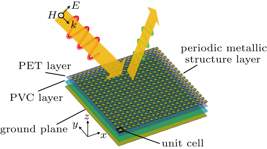
In this paper, we design a reflective broadband linear polarizer composed of metallic disks and asymmetric arc metallic wires placed over flexible substrates. The long arc metallic wire resonator provides the main resonances. The short arc metallic wire and the metallic disk work as couplers to adjust the resonance frequencies and intensities. Both simulated and experimental results have demonstrated that the designed polarizer has a wide operating bandwidth from 11.3 GHz to 20.2 GHz under normal incidence of both x- and y-polarized waves. It can also keep high-efficient polarization conversion when the incident angle increases from 0° to 45°. The designed polarization device can also be applied for conformal design due to flexible substrates. The simulation and experiment results have demonstrated that our proposed polarizer can still keep high polarization conversion efficiency even when adhered to convex cylindrical surfaces. The proposed periodical metallic structure has great potential application values in the microwave, terahertz, and optic regimes.
Figure 

 | Fig. 2. The unit cell of the metasurface: (a) front view of the unit cell, and (b) intuitive scheme of x- to y-polarization EM wave conversion of the metasurface. |
To illuminate the polarization conversion theory, we assume that an x-polarized electromagnetic wave is normally incident on the polarization converter (the same as a y-polarized wave). The electronic field of the incident electromagnetic wave denoted as 


 |
 |


 |


Then, if conditions
 |
 |
 |
Figure 
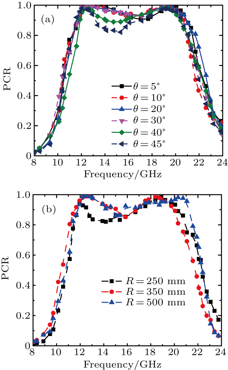
To verify the wideband property of the designed metasurface, full-wave simulations are performed with frequency domain solver in CST Microwave Studio. We set the periodic boundary conditions in x and y directions and open conditions along the z-axis. The polarization conversion ratio (PCR) can be defined as
 |
To investigate the effects of the metallic disk on polarization conversion, we have carried out numerical simulations by changing the radius of the metallic disk. Figure
 | Fig. 5. Simulated co-polarization reflection coefficients with r3 varying from 1.1 mm to 1.6 mm. (a) Incident angle θ = 0°; (b) θ = 40°. |
The most important criterion for obtaining a very weak angular dependence is to avoid coupling to propagating first negative diffraction orders, which is related to the unit cell periodicity p of the polarization conversion metasurface according to Braggʼs law.[46] In addition, the thickness of the substrate also exerts strong influence on the angle independence.[33] As shown in Fig. 


 |


 | Fig. 7. Schematic diagram of EM wave propagation in (a) two dielectric plates and (b) a dielectric plate for oblique incidence. |
Our designed polarizer has optimized the size and thickness of the unit cell; here, we make a comparison with some other reflection linear polarization converters in Table 


| Table 1.
Comparison with other wideband polarization conversion metasurfaces. . |
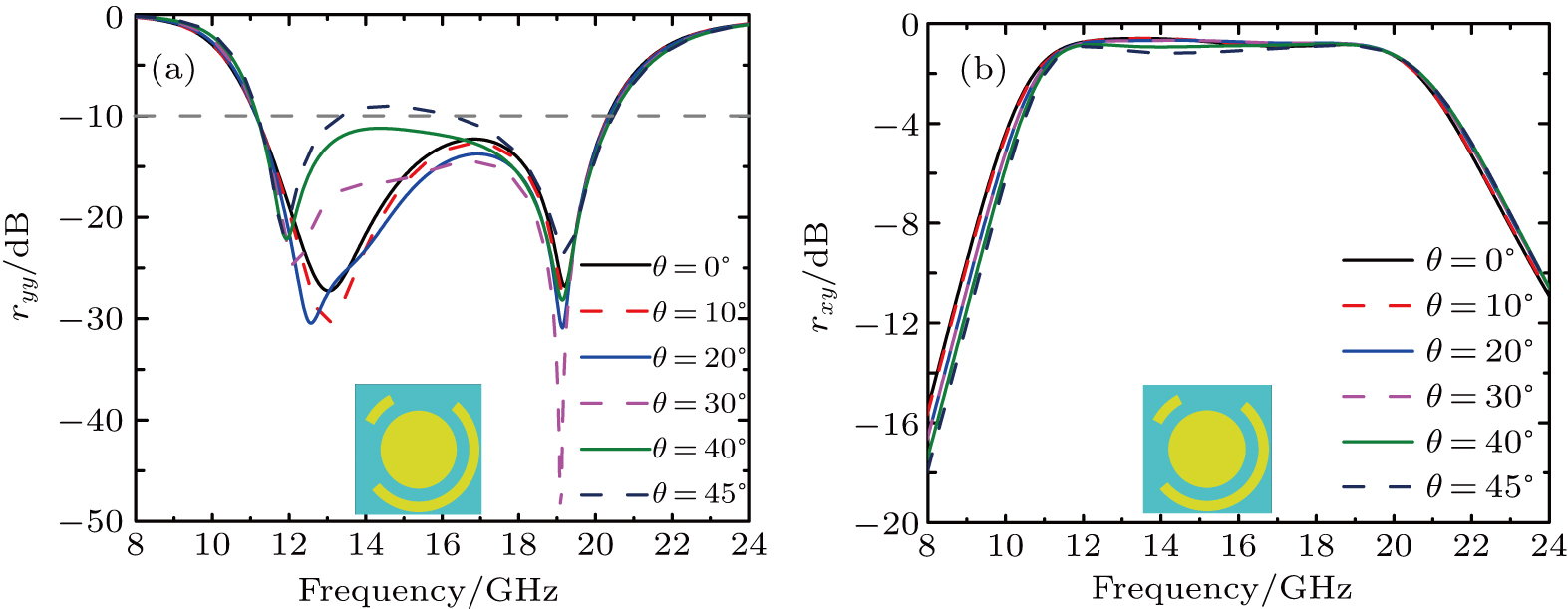
Then, we study the polarization conversion of the optimized structure under the oblique incidence of y-polarized EM waves. Figure
From the perspective of resonances, the surface current distributions are given in Fig.
We can find that the current on the metallic ground sheet at 14.0 GHz in Fig.
Furthermore, it can be seen that most of the current distributes on the long arc metallic wire and metallic disk and a little on the short arc metallic wire, which confirms long arc metallic wire and metallic disk make greater contributions to resonances.
It is also necessary to point out that the y-polarized wave (the same as the x-polarized wave) could excite all the three resonant modes (I), (II), and (III) in Fig.
To study the conformal performance, the designed polarizer and the pure metallic sheet are bent on convex cylindrical surfaces respectively with different curvature radii R = 250 mm and R = 500 mm, as shown in Figs. 

 |


To experimentally show properties of the proposed polarization converter, some prototypes are fabricated on PET substrate and stuck on the PVC substrate with these parameters d1 = 0.12 mm, d2 = 2 mm, w = 0.4 mm, r1 = r2 = 2.4 mm, r3 = 1.5 mm, α = 190°, and β = 33°. Figure
 | Fig. 12. Fabricated metasurfaces with parameters: d1 = 0.12 mm, d2 = 2 mm, w = 0.4 mm, r1 = r2 = 2.4 mm, r3 = 1.5 mm, α = 190°, and β = 33°, and experimental setup. |
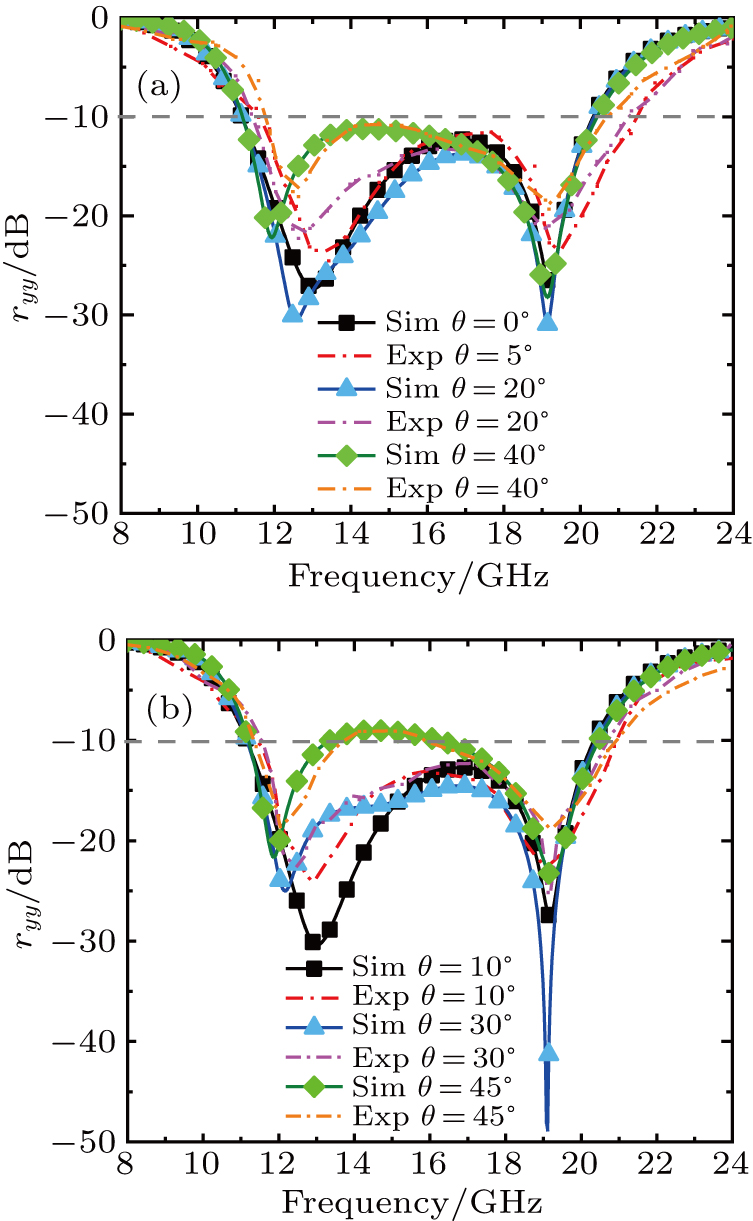
Figure
 | Fig. 13. The simulated and measured magnitude of ryy (a) with θ = 0°, 20°, and 40°; (b) with θ = 10°, 30°, and 45°. |
 | Fig. 14. The simulated and measured magnitude of rxy (a) with θ = 0°, 20°, and 40°; (b) with θ = 10°, 30°, and 45°. |
In this paper, we have proposed a high-efficient, broadband, and wide-angle reflective polarization converter based on flexible metasurface at microwave band. The operation bandwidth has been expanded greatly because of the presence of these resonances. The physics mechanism is illustrated by simulating the reflected amplitudes and phase differences between u- and v-polarized incident EM waves. Due to the combination of the first two resonances into one and the optimized size and thickness of the unit cell, the polarization converter can keep high-efficient polarization conversion over a broadband frequency range when the angle of incident electromagnetic waves varies from 0° to 45°. The surface current distributions at resonant frequencies are also given to further analyze the physical mechanism of the polarizer. Both the simulation and the experimental results have shown that the values of PCR can keep over 90% from 11.2 GHz to 20.3 GHz when the incidence angle changes from 0° to 40°. Additionally, the sample stuck on convex cylindrical surfaces with different curvature radii R is tested, and the tested results show good polarization conversion and flexibility of our designed polarizer. Compared with previous research, this can not only have wide bandwidth, high efficiency, and a weak angular dependence but can also be conformal with the surfaces of the automobiles, airplanes, steamships, and so on. The designed structure has great potential application values in the microwave, terahertz, and optic regimes.
| [1] | |
| [2] | |
| [3] | |
| [4] | |
| [5] | |
| [6] | |
| [7] | |
| [8] | |
| [9] | |
| [10] | |
| [11] | |
| [12] | |
| [13] | |
| [14] | |
| [15] | |
| [16] | |
| [17] | |
| [18] | |
| [19] | |
| [20] | |
| [21] | |
| [22] | |
| [23] | |
| [24] | |
| [25] | |
| [26] | |
| [27] | |
| [28] | |
| [29] | |
| [30] | |
| [31] | |
| [32] | |
| [33] | |
| [34] | |
| [35] | |
| [36] | |
| [37] | |
| [38] | |
| [39] | |
| [40] | |
| [41] | |
| [42] | |
| [43] | |
| [44] | |
| [45] | |
| [46] |


