New hybrid FDTD algorithm for electromagnetic problem analysis
He Xin-Bo1, 2, Wei Bing1, 2, †, Fan Kai-Hang1, 2, Li Yi-Wen3, Wei Xiao-Long3
School of Physics and Optoelectronic Engineering, Xidian University, Xi’an 710071, China
Collaborative Innovation Center of Information Sensing and Understanding at Xidian University, Xi’an 710071, China
Science and Technology on Plasma Dynamic Laboratory, Airforce Engineering University, Xi’an 710038, China


† Corresponding author. E-mail: bwei@xidian.edu.cn

Project supported by the National Natural Science Foundation of China (Grant No. 61571348) and the Equipment Pre-Research Foundation of China (Grant No. 61405180202).

Abstract

Since the time step of the traditional finite-difference time-domain (FDTD) method is limited by the small grid size, it is inefficient when dealing with the electromagnetic problems of multi-scale structures. Therefore, the explicit and unconditionally stable FDTD (US-FDTD) approach has been developed to break through the limitation of Courant–Friedrich–Levy (CFL) condition. However, the eigenvalues and eigenvectors of the system matrix must be calculated before the time iteration in the explicit US-FDTD. Moreover, the eigenvalue decomposition is also time consuming, especially for complex electromagnetic problems in practical application. In addition, compared with the traditional FDTD method, the explicit US-FDTD method is more difficult to introduce the absorbing boundary and plane wave. To solve the drawbacks of the traditional FDTD and the explicit US-FDTD, a new hybrid FDTD algorithm is proposed in this paper. This combines the explicit US-FDTD with the traditional FDTD, which not only overcomes the limitation of CFL condition but also reduces the system matrix dimension, and introduces the plane wave and the perfectly matched layer (PML) absorption boundary conveniently. With the hybrid algorithm, the calculation of the eigenvalues is only required in the fine mesh region and adjacent coarse mesh region. Therefore, the calculation efficiency is greatly enhanced. Furthermore, the plane wave and the absorption boundary introduction of the traditional FDTD method can be directly utilized. Numerical results demonstrate the effectiveness, accuracy, stability, and convenience of this hybrid algorithm.

1. Introduction

The finite-difference time-domain (FDTD) method is a very popular time-domain algorithm in electromagnetics.[1,2] Nevertheless, due to the limitation of the Courant–Friedrich–Levy (CFL) condition, it is inefficient to deal with the electromagnetic problems of objects with multi-scale structures or fine structures. To break through the limitation of CFL condition, unconditionally stable FDTD (US-FDTD) methods have been proposed. At present, unconditionally stable techniques subject to significant usage or research interest fall into three categories, including alternating-Direction Implicit (ADI) and Locally One-Dimensional (LOD) schemes, orthogonal expansions in time and removal of unstable eigenmodes of the spatial discretization.[3] Among them, ADI[46] and LOD,[7,8] orthogonal expansions are implicit methods.[912] Namely, the inverse of the matrix is necessary to be solved in the process of iteration. Although these implicit methods are unconditionally stable, they also have some disadvantages. The numerical dispersion errors of ADI-FDTD and LOD-FDTD increase markedly when the time step exceeds the CFL condition. The orthogonal expansions in time methods have a considerably more complicated formulation than the traditional FDTD, if the calculation scale is large relative to the wavelength, the computation efficiency of these methods is not practical. Removal of unstable eigenmodes of the spatial discretization is an explicit method that does not sacrifice the calculation accuracy.[13,14] This explicit method avoids matrix inversion, but it requires eigenvalue decomposition of matrix before time iteration to filter out unstable modes. Calculating the eigenvalues of a large matrix is also time consuming. In addition, the excitation of plane wave and disposal of PML absorbing boundary are complicated.

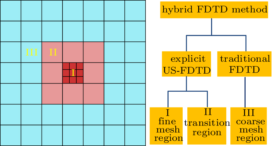
In view of these problems, a hybrid FDTD algorithm is proposed in this paper. The computational domain is divided into three regions, denoted by I, II, and III; as shown in Fig. 1. Region I represents the fine mesh area, region II represents the transition area between fine mesh and coarse mesh, and region III represents the coarse mesh area. Region I and region II constitute the computational region of the explicit US-FDTD method, and region III is the computational region of the traditional FDTD method. Since region I only occupies a small proportion in the entire calculation area, region II requires only one layer of FDTD cells, and the unstable modes are only generated by the mesh of the regions I and II. If the system matrix is composed of the entire calculation area, then it will result in a great waste of computing resources. The hybrid algorithm proposed in this paper makes it possible to construct the system matrix only in regions I and II, and it filters out the unstable modes according to the time step determined by the coarse mesh in region III. Thus, it is only necessary to calculate the eigenvalues of the system matrix consisting of regions I and II. Accordingly, the identical time step is applied in the whole computation region after removing the unstable eigenmodes. Moreover, the plane wave and PML absorbing boundary can be adopted more easily. Numerical examples involving radiation problem and scattering problem have illustrated the effectiveness, accuracy, stability, and convenience of the proposed hybrid FDTD algorithm.

Fig. 1. Classification of calculation area of the hybrid FDTD method.
2. Introduction to the explicit US-FDTD algorithm

For convenience, take the lossless problem as an example. The curl equations of Maxwell can be discretized into the following forms:[15,16] where {h} represents the vector of all magnetic field unknowns , {e} is the vector of all electric field unknowns , {j} is the current source vector, represents the time step, superscripts n, n+1, n±1/2 denote time instants. denotes a discretized operation, represents a discretized operation. and are diagonal matrices and the diagonal entries are 1/ε, 1/μ, respectively.

By substituting Eq. (1) into Eq. (2), we can get the following form: Changing n+1 to n, n to , and n+1/2 to , the following equation can be obtained: According to Eqs. (3) and (4), we can get the following second-order equation in time for {e}: where is actually at the n-th time instant. Equation (5) is a central-difference based discretization of the following second-order wave equation: where is a sparse matrix composed of discrete operators , which is called the system matrix, and it is only related to the grid size and the media parameters of the mesh.

The explicit marching can then be carried out using the update system matrix as There are stable modes and unstable modes in . The eigenvalues corresponding to the unstable modes satisfy the following formula:[14] where λ is the eigenvalue of , and the unstable modes can be filtered out by the following equation to obtain unconditional stability: where is the eigenvector corresponding to the eigenvalue which satisfies Eq. (9), and is the matrix with stable modes. Replacing in Eq. (8) by , equation (8) becomes an explicit unconditionally stable iterative equation. After obtaining the solution of from Eq. (8), we need to add one more important step to make the solution correct, i.e.,

3. Proposed hybrid method
3.1. The principle of the hybrid algorithm

The hybrid FDTD algorithm is developed in this paper by combining the explicit US-FDTD with the traditional FDTD method. According to Ref. [17], the instability is caused by the fine mesh and the adjacent coarse mesh. Consequently, the hybrid method is possible to be adopted, in which the time step can be determined according to the grid size of the region III, and then filters out the unstable modes in the regions I and II.

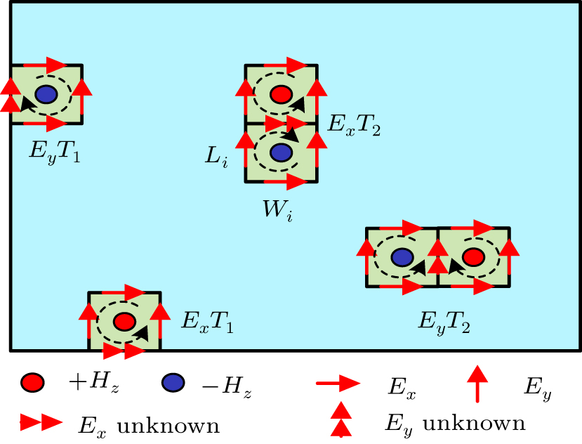
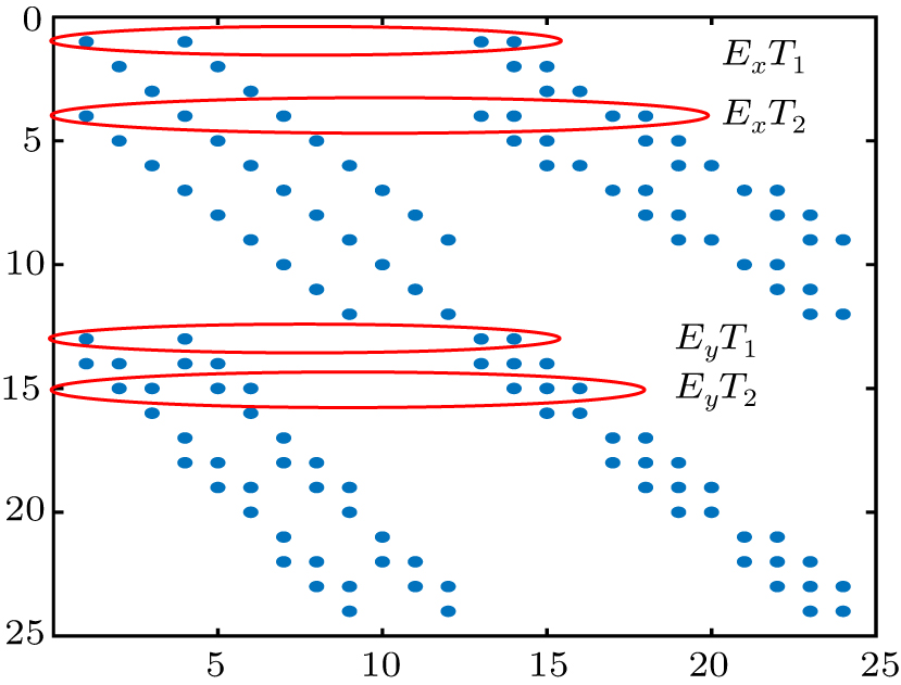
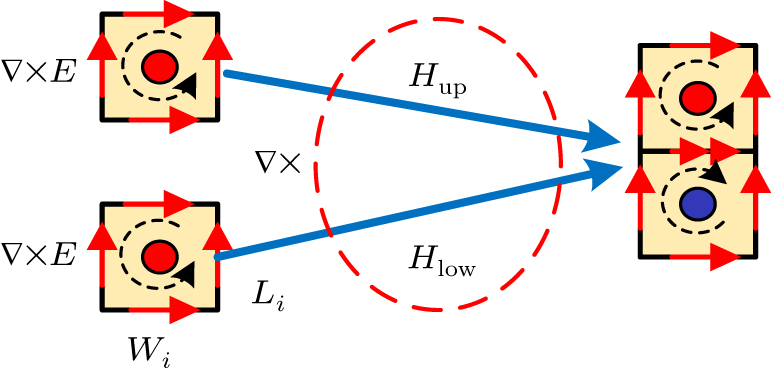
For the two-dimensional TE wave (Hz, Ex, Ey), the component of the electric field along the x direction Ex can be divided into two categories; i.e., the boundary electric field and the internal electric field . Similarly, the component along y direction Ey can also be divided into and , as shown in Fig. 2. The nonzero elements of in Fig. 3 indicate the spatial correlation between each electric field at time step n+1 and other electric fields at time step n. Obviously, the boundary electric field ( , ) is related to other four fields while the internal electric field ( , ) is related to other seven fields. It should be noted that the diagonal elements of represent the relationship between the electric field at the current moment and the electric field at the previous moment. To show the essence of the second-order iterative equation clearly, we decompose the curl operator of space, as shown in Fig. 4. Li and Wi are the side lengths of the patch. The magnetic field Hup can be obtained from the electric fields around the upper patch, and the magnetic field Hlow can be obtained from the electric fields around the lower patch. Evidently, the curl of the magnetic field around the Ex is .

Fig. 2. Classification of calculation area of explicit US-FDTD method.
Fig. 3. Distribution of nonzero elements of system matrix .
Fig. 4. Essence of the second-order iterative equation.

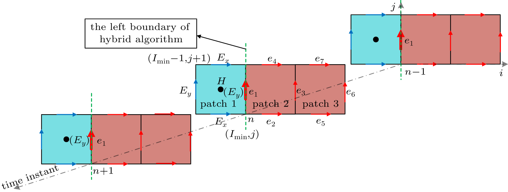
The key of the hybrid algorithm is the processing of the boundary, and the boundary is only related to the space. The explicit US-FDTD uses a second-order iteration equation of electric field. In the time domain, the electric field at time instant n+1 is related to the electric field at time instant n and . In space domain, the electric field is related to all the electric fields on the patches to which it belongs. As shown in Fig. 5, e3 is the internal electric field, which is common to patch 2 and patch 3, there are seven electric fields on the two patches, so the number of non-zero elements of the row corresponding to e3 in the matrix is seven. e1 is the left boundary electric field, it only belongs to patch 2 in the explicit US-FDTD calculation region, and the number of non-zero elements of the row corresponding to e1 in the matrix is four. From these analyses, we can see that the contribution of patch 1 to the e1 is not included in the matrix. Therefore, we need to add the contribution of patch 1 in the traditional FDTD calculation region to the explicit US-FDTD iteration; i.e., adding the contribution of the electric fields , , , at time instant n on patch 1 to the electric field e1 at time n+1. It should be noted that and e1 represent the same electric field. The traditional FDTD method uses a first-order iterative equation, and it is only necessary to pass e1 to the at time n+1. Taking the left boundary e1 as an example, the amended formula of the explicit US-FDTD calculation region is as follows: where c1, c2, c3, and c4 are the correction factors, under the circumstance of , the absolute values of these coefficients are , and the sign can be determined according to the direction of the right hand spiral in Fig. 2.

Fig. 5. Field at the boundary of hybrid algorithm.
3.2. Plane wave and PML absorbing boundary

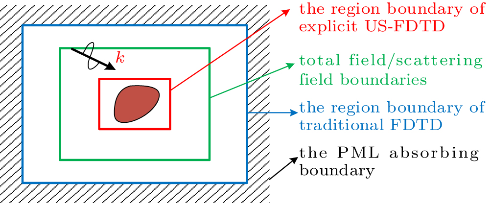
For the propagation and scattering problems, it is necessary to introduce the plane wave and the excellent absorbing boundary into the calculation area. For this purpose, this paper presents a simple method to add the plane wave and the perfectly matched layer (PML) absorbing boundary in the calculation area. Regarding this method, the boundaries in the explicit US-FDTD and the traditional FDTD are combined. Figure 6 shows the four types of boundaries in the calculation area; i.e., the region boundary of explicit US-FDTD, the total field/scattering field boundary, the region boundary of the traditional FDTD and the PML absorbing boundary. The explicit US-FDTD is utilized in the region enclosed with the red rectangular and the traditional FDTD is employed in other regions. One-dimensional FDTD is used to generate a plane wave electromagnetic field, and then the plane wave is projected onto the boundaries of the total field/scattering field. Finally, a uniform plane wave with little leakage can be obtained. The PML absorbing boundary of the traditional FDTD method can be used directly, the convolutional perfectly matched layer (CPML) is adopted in this paper.

Fig. 6. Classification of calculation area of propagation problem.
4. Numerical examples
4.1. Radiation problem

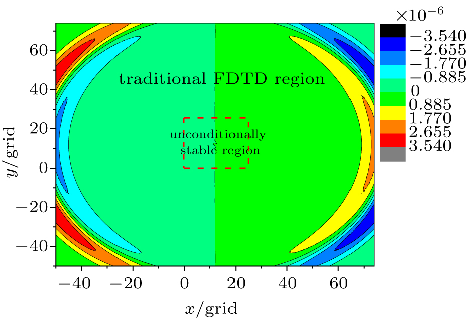
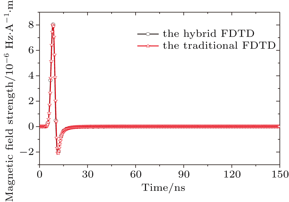
The size of the calculation area is 12.5 m × 12.5 m and the coarse grid size is Lc = 0.1 m. The entire calculation area is discretized into 125 × 125 coarse grids, and the calculation in the area composed by the central 25 × 25 grids is done with the explicit US-FDTD, and the calculation in the rest area is conducted by the traditional FDTD. A coarse mesh at the center of the explicit US-FDTD calculation region is refined with a size ratio of n = 15. A Gaussian current source along the y direction is located at the center of the fine mesh in the form , where and . The boundary is terminated by CPML. The time step used for the hybrid FDTD method is 1.6667 × 10⁻¹⁰ s, while the time step used by the traditional FDTD method is 1.1111 × 10⁻¹¹ s. The magnetic field distribution in the calculation area at a certain time is shown in Fig. 7. To show the good ability of the proposed method, we randomly take a monitoring point in the calculation area, and compare the time domain waveform of the point with the time domain waveform obtained by the traditional FDTD method, as shown in Fig. 8. As can be seen from Fig. 8, the results of the hybrid algorithm and the traditional FDTD algorithm agree well. The time and the dimension of system matrix for each method are shown in Table 1. The total consumed time for the hybrid algorithm is 11.15 s, while it is 218.95 s for the traditional FDTD algorithm. The traditional FDTD is matrix-free, thus there is no system matrix for the traditional FDTD. In addition, it should be noted that in this case, if only the explicit US-FDTD algorithm is used, then the dimension of the system matrix is 31920, and it is difficult to perform the eigenvalue decomposition. Therefore, the column corresponding to the time of explicit US-FDTD is represented by the symbol ‘/’ in Table 1. However, the hybrid method reduces the matrix dimension 1720, and the computational efficiency is greatly improved.

Fig. 7. Snapshot of the magnetic field at a certain moment.
Fig. 8. Time domain waveform of the monitoring point.
Table 1.

Results of the dimension of the system matrix and time of different methods.

.
4.2. Scattering problem

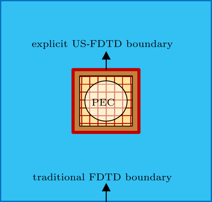
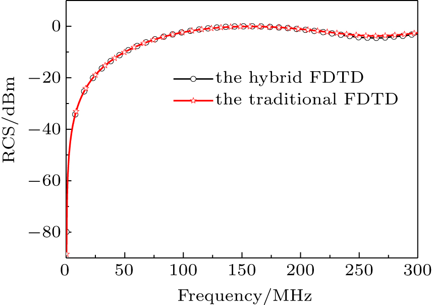
The second example is the scattering problem of an infinite PEC cylinder. The maximum frequency of incident wave is 300 MHz, and the radius of the cylinder is 0.25 m. The size of the calculation area including absorbing boundary is 2 m × 2 m. The cylinder is located at the center of the calculation region. The coarse grid size Lc is 0.05 m, and the region of the cylinder is subdivided into fine cells with the contrast ratio being n = 3. Therefore, the fine grid size Lf is 0.0167 m. The computational model of hybrid method is shown in Fig. 9, the explicit US-FDTD method is adopted in the surrounding area of the cylinder, and the remainder is calculated by traditional FDTD method. In this example, we also simulate the same problem using the traditional FDTD method with uniform fine grids. The traditional FDTD method must use a time step no greater than s to perform a stable simulation. In contrast, the proposed hybrid method is able to use a time step of s solely determined by size of the coarse grid to carry out the simulation. Fig. 10 illustrates the backscattering of the cylinder. Obviously, an excellent agreement is indicated between the proposed hybrid method with the traditional FDTD method.

Fig. 9. The computational model of hybrid method.
Fig. 10. The backscattering of the PEC cylinder.
5. Conclusions

A new hybrid FDTD method is proposed in this paper. The time step of this hybrid method is only determined by the coarse mesh, thus this method can achieve unconditional stability. This hybrid method can also reduce the matrix size of eigenvalue decomposition and can greatly improve the computational efficiency. Moreover, the hybrid approach successfully introduces the plane wave and PML absorbing boundary into the calculation area, which increases the convenience of simulation. All of the numerical comparisons show the good availability of the proposed hybrid method and the advantages of the proposed method lays the foundation to the analyses of complex multi-scale structures in the future.

Reference
[1] Li J Guo L X Zeng H Han X B 2009 Chin. Phys. B 18 2757
[2] Lu J Zhou H C 2016 Chin. Phys. B 25 090203
[3] Taflove A Hagness S C 2016 Finite-Difference Time-Domain Solution of Maxwell’s Equations New York John Wiley & Sons, Inc 9 10.1002/047134608X.W8303
[4] Namiki T 1999 IEEE Trans. Microw Theory. Techn. 47 2003
[5] Zheng F H Chen Z Z Zhang J Z 1999 IEEE Microwave Guided Wave Lett. 9 441
[6] Liu S B Liu S Q 2004 Chin. Phys. 13 1892
[7] Shibayama J Muraki M Yamauchi J Nakano H 2005 Electron. Lett. 41 1046
[8] Wei X K Shao W Shi S B Zhang Y Wang B Z 2015 Chin. Phys. B 24 070203
[9] Chung Y S Sarkar T K Jung B H Salazar-Palma M 2003 IEEE Trans. Microw. Theory. Techn. 51 697
[10] Yi Y Chen B Chen H L Fang D G 2007 IEEE Microwave Wireless Compon. Lett. 17 91
[11] Huang Z Y Shi L H Chen B Zhou Y H 2014 IEEE Trans. Antennas Propag. 62 4804
[12] Huang Z Y Shi L H Zhou Y Chen B 2015 Electron. Lett. 51 1654
[13] Gaffar M Jiao D 2014 IEEE Trans. Microwave Theory Tech. 62 2538
[14] Gaffar M Jiao D 2015 IEEE Trans. Microwave Theory Tech. 63 4215
[15] Gedney S D 2011 Introduction to the finite-difference time-domain (FDTD) method for electromagnetics USA Morgan & Claypool 48 10.2200/S00316ED1V01Y201012CEM027
[16] Yan J Jiao D 2016 Int. Microwave Symp. IMS, San Francisco, United States 10.1109/MWSYM.2016.7540416
[17] Yan J Jiao D 2017 IEEE Trans. Microw Theory. Tech. 65 5084