

Fast Fourier single-pixel imaging based on Sierra–Lite dithering algorithm
Cite this Article
Liang Zhen-Yu, Cheng Zheng-Dong, Liu Yan-Yan, Yu Kuai-Kuai, Hu Yang-Di. Fast Fourier single-pixel imaging based on Sierra–Lite dithering algorithm. Chinese Physics B, 2019, 28(6): 064202 
Permissions
Fast Fourier single-pixel imaging based on Sierra–Lite dithering algorithm
† Corresponding author. E-mail:
Abstract
The single-pixel imaging (SPI) technique is able to capture two-dimensional (2D) images without conventional array sensors by using a photodiode. As a novel scheme, Fourier single-pixel imaging (FSI) has been proven capable of reconstructing high-quality images. Due to the fact that the Fourier basis patterns (also known as grayscale sinusoidal patterns) cannot be well displayed on the digital micromirror device (DMD), a fast FSI system is proposed to solve this problem by binarizing Fourier pattern through a dithering algorithm. However, the traditional dithering algorithm leads to low quality as the extra noise is inevitably induced in the reconstructed images. In this paper, we report a better dithering algorithm to binarize Fourier pattern, which utilizes the Sierra–Lite kernel function by a serpentine scanning method. Numerical simulation and experiment demonstrate that the proposed algorithm is able to achieve higher quality under different sampling ratios.
1. Introduction
In conventional imaging systems, a sensor array is generally required to capture a two-dimensional (2D) image of a scene by collecting light focused through an optical lens. An innovative approach, known as single-pixel imaging (SPI), replaces the multi-pixel sensor with a single photosensitive detector as the imaging device by utilizing a spatial light modulator (SLM) or digital micromirror device (DMD) to provide either time-varying, structured detection of the scene or time-varying, structured illumination onto the scene. The final image is retrieved by correlating the recorded intensity signal with the corresponding structured illumination. The SPI shares the same scheme to ghost imaging (GI),[1–6] and it is often considered to originate from GI.
By capturing 2D images using a single-pixel detector (usually a photodiode), SPI has huge advantages, such as robustness to light scattering, flexible system configuration,[7,8] and low cost, and has been widely applied to three-dimensional (3D) imaging,[9–11] multi-spectral imaging,[12,13] optical encryption, etc. However, low image quality and speed still restrict the development of single-pixel imaging. In recent years, Fourier single-pixel imaging (FSI) technique[12–22] has attracted much attention because it can reconstruct high-quality images by using Fourier basis patterns (also known as grayscale sinusoidal patterns) for illumination. Each four π/2 phase-shifted sinusoidal patterns owning the same single spatial frequency and yielding the scene Fourier coefficient at the spatial spectrum of the scene can be obtained. Then, inverse Fourier transform is applied to reconstruct the scene. Concerning experimental results, this technique has been proven capable of achieving sub-millimetric depth accuracy in multi-modality 3D imaging,[10] imaging,[13] shadow-free imaging,[22] etc. But, from a practical point of view, the grayscale illuminating patterns cannot fully take the advantages of DMD high frame rate binary modulation, which is the key component to achieve the real-time imaging. Therefore, fast FSI system[16] is proposed to solve this problem by using binary Fourier pattern through dithering algorithm, while the dithered pattern would inevitably lead to extra noise in the reconstructed image and the image quality cannot reach the requirement for practical application.
In this paper, the principle of the dithering algorithm is investigated. From the theoretical analysis, we report a better dithering algorithm to binarize Fourier pattern, which utilizes the Sierra–Lite kernel function by a serpentine scanning method. This allows us to achieve higher image quality under the same sampling ratio through the numerical simulation and optical experiment. Consequently, the reported method raises the accuracy of grayscale pattern generation of DMD-based FSI in binary mode and provides an alternative approach to improve FSI image quality.
2. Theory
2.1. Phase-shifting Fourier single-pixel imaging
where (x,y) is two-dimensional Cartesian coordinates, a is the average intensity of the pattern, and b is the contrast. The sinusoidal patterns are sequentially projected on a commercial digital projector and then illuminated onto the targets as structured illumination. The total intensity of the reflected light from the targets can be expressed as
where

is the illuminated area, and R(x,y) represents the distribution of the surface reflectivity of the imaged targets in the scene. The four-step or three-step phase-shifting algorithm is applied to obtain the complex Fourier coefficients of different frequencies to retrieve the Fourier spectrum of the scene. For the four-step phase-shifting algorithm, each spatial frequency pair

corresponds to four different phases (ϕ =0, π/2, π, and 3π/2). Applying the following equation, we can obtain the complex-valued Fourier spectrum

by illuminating four patterns and using four corresponding response (D0,

,

, and

) for calculation
For the three-step phase-shifting algorithm, the Fourier spectrum

can be retrieved by using three corresponding response (D0,

, and

) for calculation
Because the conjugate symmetry of the Fourier spectrum of natural images allows for perfect reconstruction by half-sampling the spectrum, it consumes only
measurements by using the four-step phase-shifting algorithm to fully sample and
measurements for the three-step phase-shifting algorithm.
In contrast from the original single-pixel imaging system directly using binary illuminating patterns, FSI uses Fourier basis patterns for illumination, and each basis pattern 


 |
 |
 |
 |
Since most of the illuminating patterns are binary modulated, the original single-pixel imaging system lends itself well to the DMD-based device by using its binary modulation (each DMD mirror has only two states ‘ON’ and ‘OFF’) at its maximum rate (∼22 kHz). However, DMD cannot generate grayscale patterns directly but only displays ∼290 Hz at its 8-bit mode. Therefore, the grayscale FSI is challenging to apply to high-speed real-time imaging by using a digital projector.
2.2. Dithering algorithm analysis
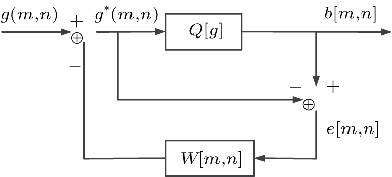
where g(m,n) is the original Fourier pattern, and

is the gray value of the original pattern after adding the quantization error of the surrounding pixel diffusion at (m,n). The quantization error e(m,n) at the pixel (m,n) is diffused to several adjacent pixels by a two-dimensional weighting function w(k,l), which is also called the kernel function.
where the threshold T is typically 128 and

represents the threshold quantization function. The quantization error e(m,n) is
The principle of the dithering algorithm due to error diffusion is illustrated in Fig. 1 .
From Eq. (8 ), the quantization error of the current pixel not only depends on the input and output pixel value at this position but also includes the influence of the processed region on the current pixel.
where “-” represents the processed pixel, x is the pixel currently being processed, and the adjacent numbers (called weights) represent the proportion of errors assigned to the location. It is also called the Floyd–Steinberg kernel function.
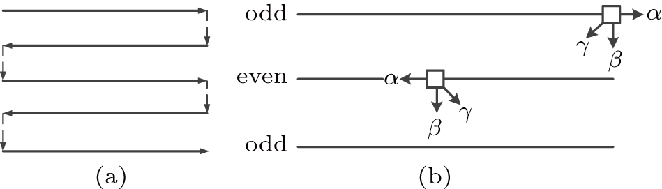
Correspondingly, the kernel function of even rows is
The serpentine scanning method is shown in Fig. 2 , where the parameters α, β, and γ represent the error diffusion coefficients in the kernel function in Fig. 2 , i.e., α =1/2, β =1/4, and γ =1/4.
To overcome the weakness for low-rate pattern generation of FSI, Zhang et al.[12] proposed to use a dithering algorithm to convert grayscale sinusoidal patterns to binary sinusoidal patterns based on the idea of error diffusion. The basic idea of the error diffusion method is to compare the current pixel value of the grayscale image with a threshold value to obtain a binary output, and then spread the pixel difference between the input and the output to the several adjacent unprocessed regions by a certain percentage.
The principle of error diffusion can be expressed as
 |
According to the threshold T, the pixel value at 
 |
 |
 | Fig. 1 Principle of the dithering algorithm due to the error diffusion. |
To facilitate the analysis of the algorithm, the quantization error e(m,n) can also be written as
 |
The kernel function w(k,l) is the most critical parameter in the error diffusion method and the dithering algorithm will be different with different kernel functions. Usually, the kernel function for traditional dithering algorithm can be expressed as
 |
Usually, the traditional algorithm can result in partial structural texture between bright and dark tones, and the boundary processing effect is not ideal in some parts. Simultaneously, the error will cause the water impact of flow and lead to the decrease of the image quality by using sequential scanning method calculating from the left-hand pixel to the right-hand pixel, and then from the top pixel to the bottom pixel. To obtain a smaller quantization error for binary Fourier patterns and better structural similarity with the grayscale Fourier patterns, we report an improved dithering algorithm by utilizing Sierra–Lite kernel function and applying serpentine scanning method; namely, the error is obtained from the left pixel to the right pixel in odd rows, and then from the right pixel to the left pixel in even rows.
Therefore, the kernel function of odd rows can be expressed as
 |
 |
 | Fig. 2 Serpentine raster scanning method and error diffusion. (a) Serpentine scanning method; (b) error diffusion coefficient in odd rows and even rows. |
3. Experiments
The feasibility of the improved dithering algorithm by utilizing the serpentine scanning method is validated by the numerical simulation and optical experiment in the subsection. We use the three-step phase-shifting algorithm, where ϕ is set to 0, 2π/3, and 4π/3, respectively.
3.1. Numerical simulation
In the numerical simulation, we first directly observe the binary sinusoidal patterns generated by the two dithering algorithms. Figure
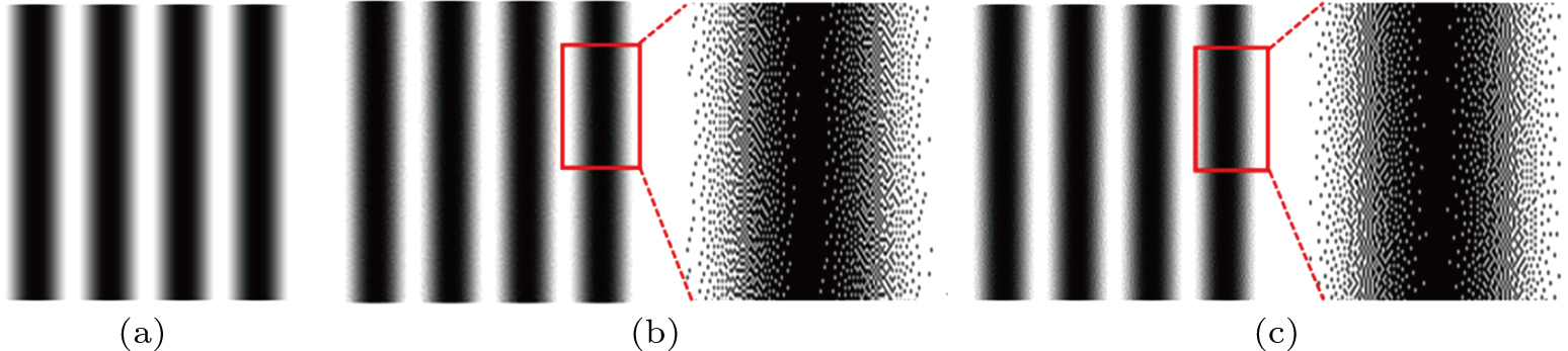 | Fig. 3 Comparison of dithered patterns by intuition. (a) Grayscale pattern; (b) Floyd–Steinberg dithered pattern; (c) Sierra–Lite dithered pattern by a serpentine scanning method. |
From Fig.
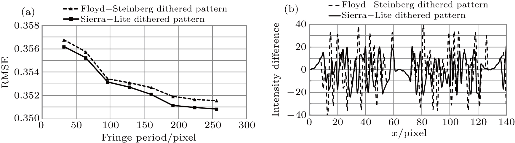
The second stage is to compare the similarity between each binary pattern and ideal grayscale sinusoidal pastern for quantitative description because higher similarity represents the excellent sinusoidality for the dithered pattern. It is certain that the Fourier spectrum of the scene image with three-step phase-shifting sinusoid illumination would be more precise. The root-mean-square error (RMSE) is applicable to describe the similarity between the dithered pattern and ideal sinusoidal pattern. Figure
 | Fig. 4 Comparison between Floyd–Steinberg dithered pattern and Sierra–Lite dithered pattern. (a) The RMSE of two dithered patterns; (b) intensity difference between dithered pattern after defocusing and the ideal sinusoidal pattern. |
It should be noted that the binary dithered pattern could be converted to grayscale by employing the defocusing techniques. Therefore, we decide to calculate any line of intensity difference to describe sinusoidality between dithered patterns after defocusing an ideal pattern. As shown in Fig.
As the results indicated in Fig.
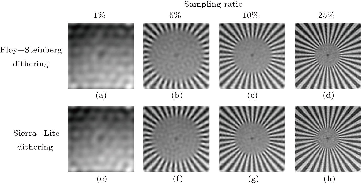
 | Fig. 5 Comparison results for testpat pattern reconstruction by FSP and SLP for different sampling ratios. |
| Table 1.
Quantitative comparison results for testpat. . |
In the following simulations, we set two widely used standard 128 × 128 pixel test images, ‘testpat’ target pattern and the Lena image, as target scenes through simulation. We use peak signal-to-noise ratio (PSNR) and structural similarity index (SSIM) to quantitatively evaluate the quality of the reconstructed images. Two algorithms are implemented using Matlab on an Intel Core i5-7200 2.5-GHz CPU computer, with 8-G RAM and 64-bit Windows 10 system. Please note that, for Tables
| Table 2.
Quantitative comparison results for Lena. . |
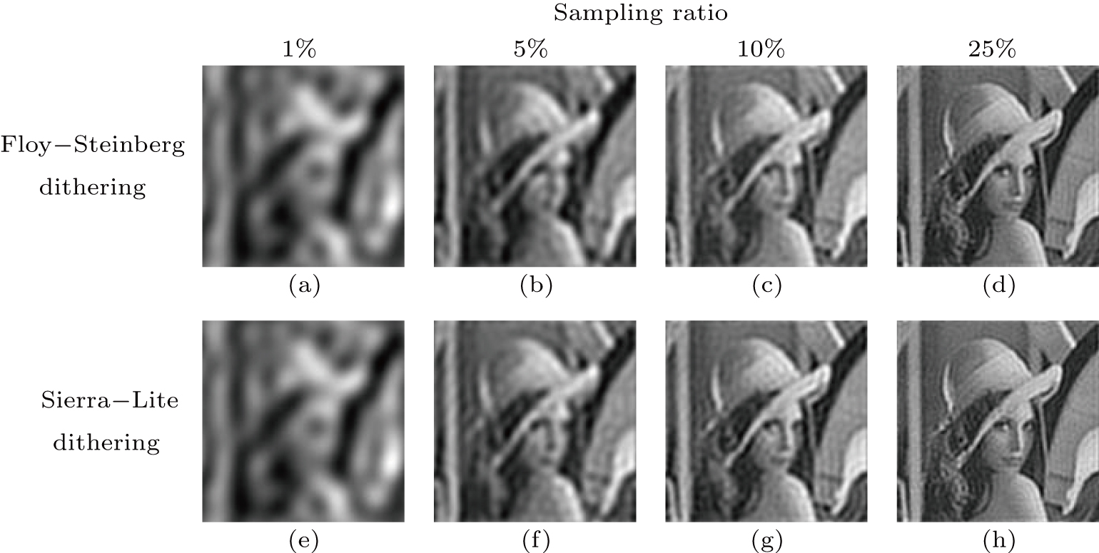
As the results in Fig.
 | Fig. 6 Comparison results for Lena image reconstruction by FSP and SLP for different sampling ratios. |
3.2. Optical experiments
where

is the average intensity of the image feature,

is the average intensity of the background, and

is the standard deviation of the background. Here, the image feature

is calculated from the image highlighted by solid white squares, and

and

are calculated from the image highlighted by the dashed-white squares in Fig. 8 8(a). The calculated results show that the SNR of the image reconstructed by Sierra–Lite dithering algorithm is ∼22% higher than that of the Floyd–Steinberg algorithm, demonstrating a better image quality.
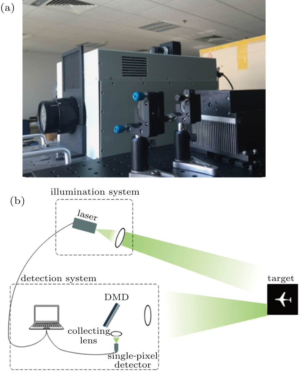
To further compare the performance of the two dithering algorithms, we have built an experimental prototype (Fig.
 | Fig. 7 Experimental setup. (a) Experimental prototype; (b) prototype schematics. |
The results are shown in Fig.
 |
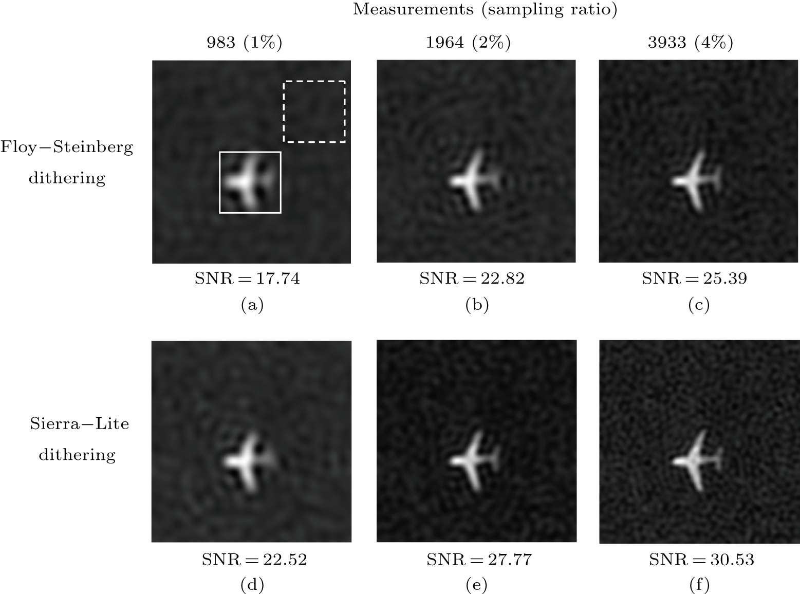 | Fig. 8 Experimental SPI results of different dithering algorithms. |
4. Conclusion and perspectives
In this work, by applying an improved dithering algorithm on the structured illumination, we have managed to use Sierra–Lite kernel function by serpentine raster scanning method to improve the image quality of the binarized Fourier single-pixel imaging. We present a specific comparison between the image quality of the Floyd–Steinberg dithering algorithm and the Sierra–Lite dithering algorithm. Numerical simulation and experimental results show that the improved binary illumination pattern of the proposed algorithm has higher similarity and better sinusoidal with the grayscale patterns than the traditional binary pattern, and the reconstructed images have better image quality. To some extent, the proposed algorithm makes both low noise and high frame rate available simultaneously, and overcomes the limitation of the high speed and low-quality trade-off in binaried Fourier single-pixel imaging. It may also push forward the development of high-quality real-time single-pixel imaging.
Reference
| [1] | |
| [2] | |
| [3] | |
| [4] | |
| [5] | |
| [6] | |
| [7] | |
| [8] | |
| [9] | |
| [10] | |
| [11] | |
| [12] | |
| [13] | |
| [14] | |
| [15] | |
| [16] | |
| [17] | |
| [18] | |
| [19] | |
| [20] | |
| [21] | |
| [22] |