Enhanced soft magnetic properties of iron powders through coating MnZn ferrite by one-step sol–gel synthesis
Liu Dong, Gao Shanmin, Jin Rencheng, Wang Feng, Chu Xiaoxiao, Gao Taiping, Wang Yubao
School of Chemistry and Materials Science, Ludong University, Yantai 264025, China


† Corresponding author. E-mail: ld_chemistry@163.com gaosm@ustc.edu

Project supported by the Natural Science Foundation of Shandong Province, China (Grant No. ZR2018MEM020).

Abstract
Abstract

The MnZn ferrite coating formed on the surface of iron-based soft magnetic powders via facile and modified sol–gel process has been fabricated to obtain better magnetic performance due to its higher permeability compared with traditional nonmagnetic insulation coatings. The influence of the MnZn ferrite contents on the magnetic performance of the soft magnetic composites (SMCs) has been studied. As the MnZn insulation content increases, the core loss first experiences a decreasing trend that is followed by progressive increase, while the permeability follows an increasing trend and subsequently degrades. The optimized magnetic performance is achieved with 2.0 wt% MnZn ferrite, which results from the decrement of inter-particle eddy current losses based on loss separation. A uniform and compact coating layer composed of MnZn ferrite and oxides with an average thickness of is obtained by utilizing ion beam technology, and the interface between the powders and the coating shows satisfied adhesiveness compared with the sample directly prepared by mechanical mixing. The evolution of the coating layers during the calcination process has been presented based on careful analysis of the composition and microstructure.

1. Introduction

Soft magnetic composites (SMCs) produced by powder metallurgy (PM) methods are of considerable interest in broad applications, such as electromagnetic conversion component in switching power cores, pulse transformers, and power factor circuits.[1,2] SMCs containing metallic magnetic powders embedded in the insulating matrix exhibit unique and fascinating magnetic properties, such as isotropic ferromagnetic behavior, high electrical resistivity, and relatively low core loss, which is most desirable for high-frequency applications.[35] Therefore, the electrical insulation coating formed on the surface of the magnetic powders is the paramount feature of the SMCs technology for increasing electrical resistivity and reducing core loss.[68]

Electrical insulation coatings for the SMCs are generally divided into three categories: organic, inorganic, and organic–inorganic hybrid coatings. The organic coatings provide satisfactory adhesion to the powders; however, most of them including epoxy and silicone resins have poor thermal stability annealed at high temperatures.[9] This hinders the internal stress relief introduced during the subsequent compaction.[10] More efforts have been devoted to the development of thermally stable inorganic and organic–inorganic hybrid coatings, such as SiO2,[9] Al2O3,[11] and SiO2/silicone,[12] which are all nonmagnetic materials leading to the decrement of the permeability and saturation magnetization of the SMCs. Zhao et al.[1315] fabricated iron oxide (mainly Fe3O4) as the ferromagnetic coatings, which have substantially reduced the magnetic dilution effect and improved the overall saturation magnetization and permeability of the SMCs. However, the formation of Fe3O4 coatings requires rigorous conditions, such as high temperature, and the electrical resistivity of Fe3O4 is relatively low. MnZn ferrite can be employed as an promising candidate because of its high resistivity and excellent magnetic properties.[16,17] Li et al.[18] obtained MnZn/FeSiAl SMCs by using the solvothermal method, which has better magnetic properties compared with mica coating. Nonetheless, the interface state between the coating and magnetic powder remains unclear and the coating layer was incomplete because the powders were mechanically mixed with as-synthesized MnZn ferrites. Moreover, few studies have focused on the characterization of the coating thickness which significantly influences the magnetic performance of SMCs.

In this study, iron powders are coated with MnZn ferrites via one-step sol–gel combustion method, showing enhanced magnetic properties. The microstructure, thickness, and composition distribution of the MnZn ferrite coatings have been revealed based on detailed analysis. The interface between the powders and coating layer is directly observed by ion beam technology and transmission electron microscopy (TEM).

2. Experimental procedures

Iron powders (20 g) were coated with MnZn ferrites (Mn0.6Zn0.4Fe2O4) by sol–gel combustion method using nitrates including Fe(NO3)3·9H2O, Zn(NO3)2·6H2O, and Mn(NO3)2 as raw materials. All the nitrates combined with citric acid C6H8O7·H2O as the complexant were completely dissolved in distilled water. The pH value of the as-received solution was then adjusted to 6 with acetic acid dropwise. The solution was heated to 60 °C in water bath and stirred for 1 h to obtain viscous sol in which iron powders were then dispersed and stirred continuously until complete evaporation of the solvent. The as-coated powders were calcined at 500 °C for 3 h prior to blending with 0.5 wt% zinc stearate as the lubricant. The mixture was then compacted into toroid cores (outer diameter = 23.4 mm, inner diameter = 14.6 mm, and thickness = 6.8 mm) at 1800 MPa followed by annealing at 550 °C in nitrogen atmosphere for 1 h.

The surface and cross-sectional morphology of the powders were characterized by scanning electron microscope (SEM, FEI Helios Nanolab 650) equipped with focused ion beam (FIB). The phase composition of the coatings was investigated using x-ray diffraction (XRD) on a Rigaku D/Max-2400 diffractometer equipped with graphite monochromatized Cu radiation. Fourier transform infrared spectrometer (FTIR, Tensor 37) was used to investigate the composition evolution of the coatings before and after calcination. The microstructure and composition distribution of the coatings was characterized by transmission electron microscope (Titan G2 80-200 ChemiSTEM) equipped with energy dispersive x-ray spectroscopy (EDS). The core loss Pcv and effective permeability of the SMCs were measured by an auto testing system (MATS-2010SA). The applied magnetic field was set at 10 mT with a frequency variation between 25 kHz and 350 kHz. The electrical resistivity of the SMCs was examined utilizing the four point probe method, while the density of the samples was measured based on the principle of Archimedes.

3. Results and discussion
3.1. Magnetic performance of the SMCs

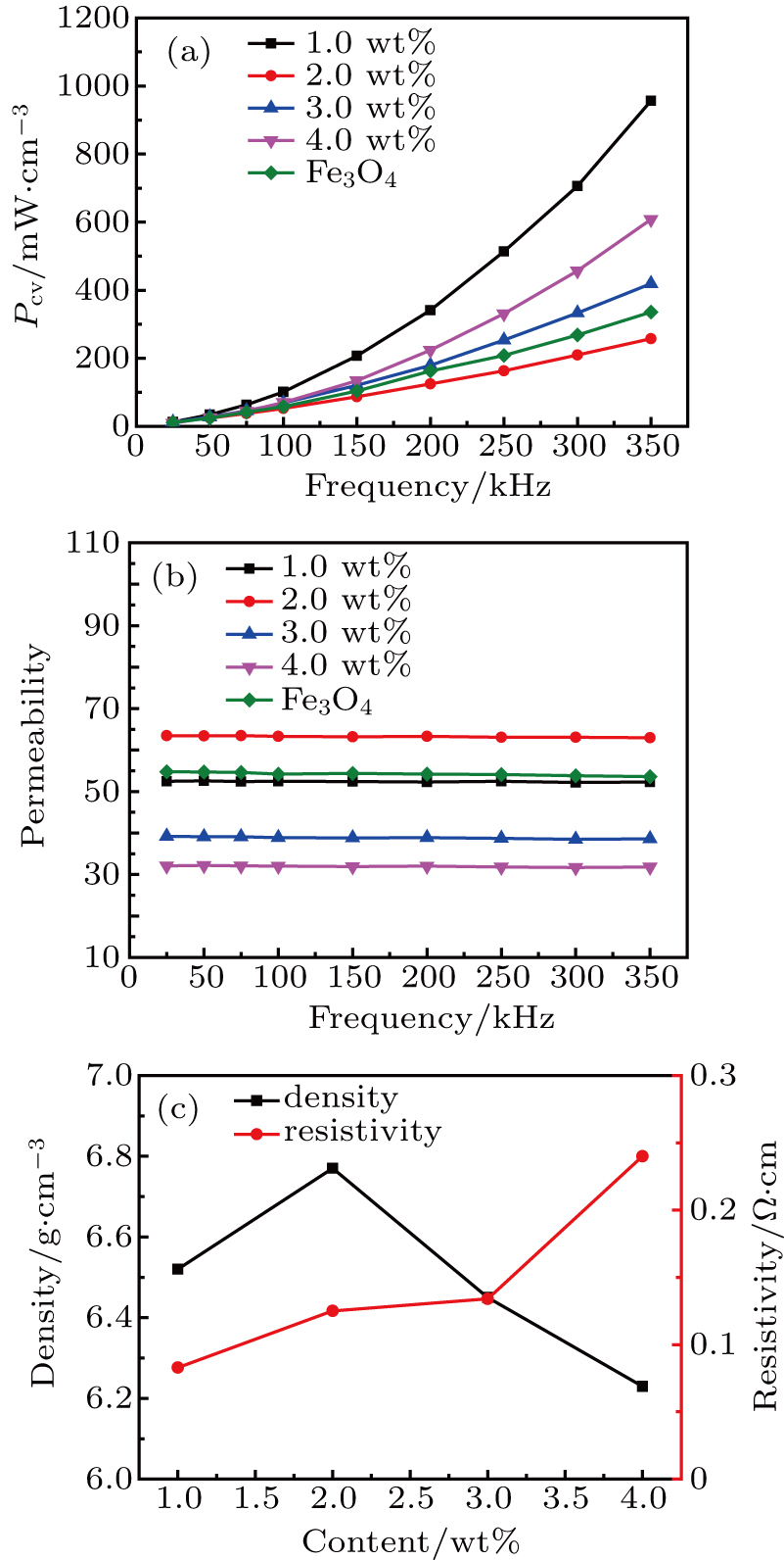
Figure 1 shows the influence of different MnZn ferrite contents on Pcv and varying from 1.0 wt% to 4.0 wt%. For comparison, Fe-based SMC coated with Fe3O4 by acidic bluing process was also prepared.[15] Figure 1(a) presents the change of Pcv, which experiences a decreasing trend with the insulation content increasing to 2.0 wt% and then continuously increases, while the electrical resistivity of the SMCs exhibits a monotonously increasing trend (Fig. 1(c)). The displays satisfactory frequency stability between 25 kHz and 350 kHz. It follows an increasing trend followed by a decrease with the increment of the MnZn ferrite contents, which is consistent with the changes in the density. Enhanced magnetic performance is obtained with 2.0 wt% MnZn ferrite, which is much better than that of Fe3O4 coating because of higher electrical resistivity. The variation in the magnetic properties of the SMCs will be further discussed in the following section.

Fig. 1. (a) Core loss and (b) effective permeability as a function of frequency for the SMCs with different MnZn ferrite contents compared with Fe3O4 coating, and (c) changes of the density and resistivity for the samples with ferrite coating.
3.2. Characterization of the ferrite coatings

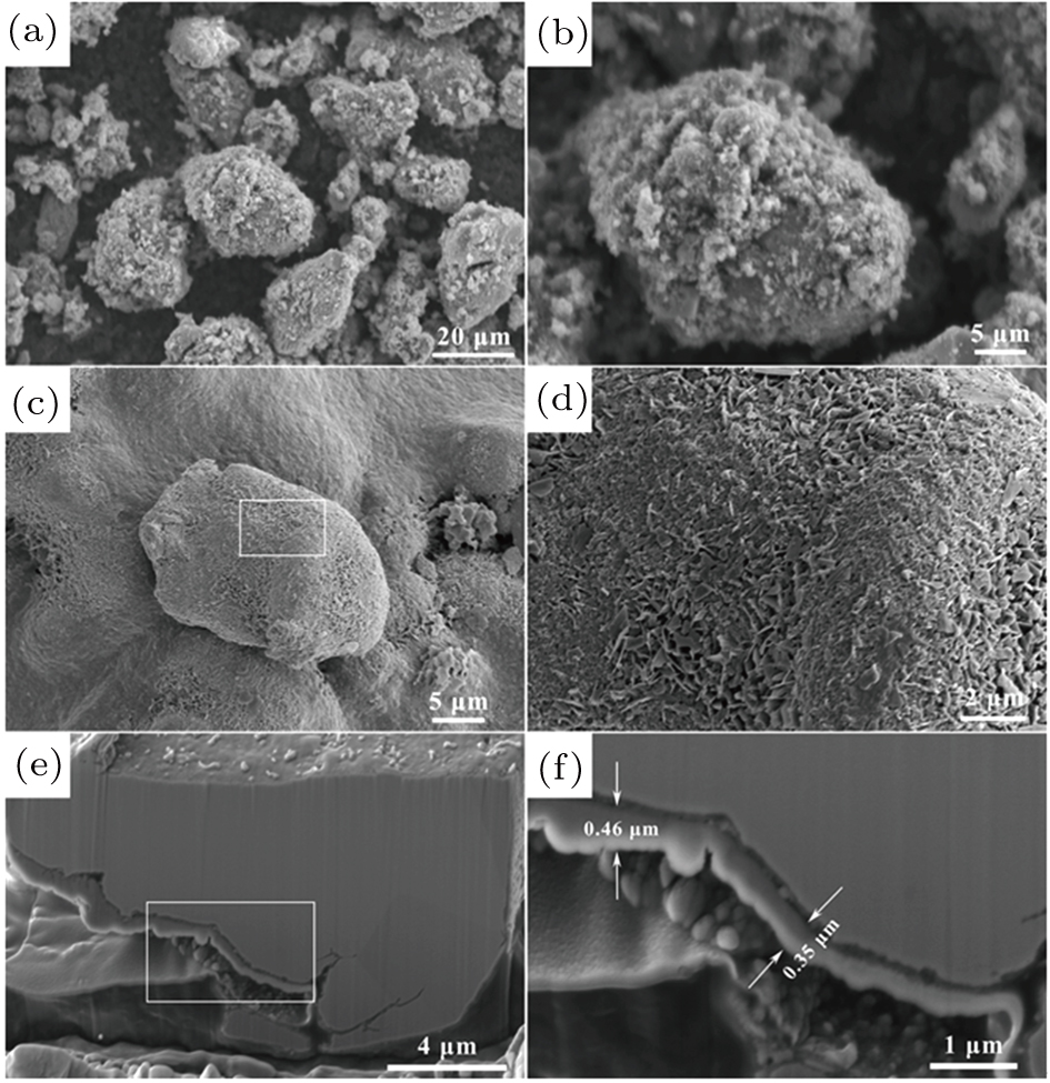
Figure 2 shows the SEM images revealing the surface and cross-sectional morphology for the Fe powders with optimized MnZn ferrites content (2.0 wt% as shown in Fig. 1). For comparison, the powders coated with equivalent MnZn ferrites prepared by directly mechanical mixing[18] are shown in Figs. 2(a) and 2(b). Uneven particles on the surface of Fe powders are observed, which could not form complete insulation coatings. With one-step sol–gel synthesis, the MnZn ferrite particles distribute uniformly and compactly (Figs. 2(c) and 2(d)) on the magnetic powders. It can be concluded that each particle has been coated with MnZn ferrite layer. Figure 2(e) and 2(f) show the cross-sectional morphology of the as-coated Fe powders, which is prepared by FIB milling. The average thickness of the insulation coating is approximately 0.38 ± by measurements at multiple regions. The existence of the air gaps distributed in magnetic particles will hinder the rotation of the magnetic domains and reduce the . Therefore, better bond strength of the insulation coating is beneficial to obtain high . It can be seen that the coating layer shows satisfied adhesiveness to the powder surface.

Fig. 2. The SEM images showing the surface morphology of the Fe powders coated with 2.0 wt% MnZn ferrites by: (a) and (b) mechanical mixing; (c) and (d) sol–gel method. (e) The cross-sectional SEM image of the as-coated Fe powder. (d) and (f) are taken from the selected rectangle regions in (c) and (e), respectively.

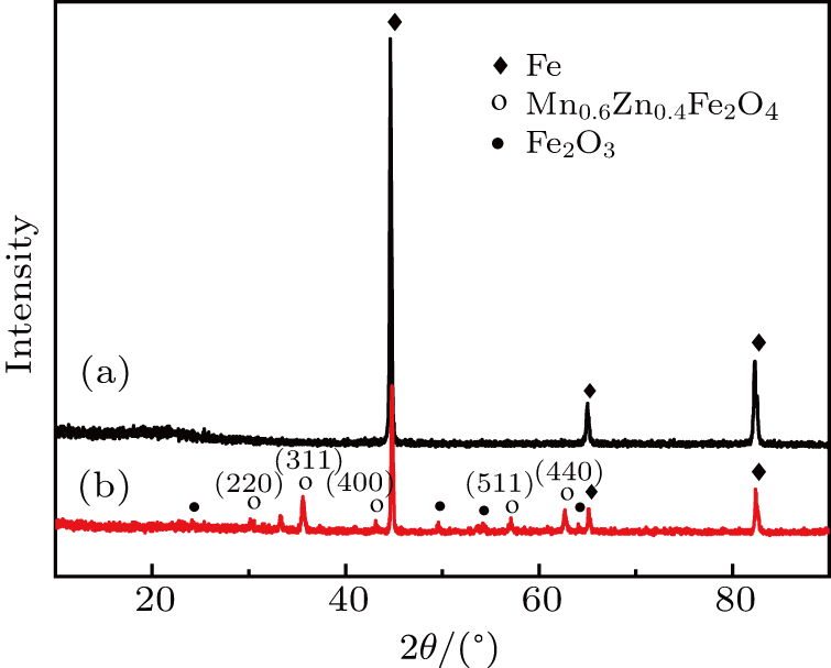
Figure 3 depicts the XRD patterns of the sample with MnZn ferrites coating compared with uncoated Fe powders. By comparing the XRD pattern of the as-coated particles with the standard diffraction spectrum, it can be concluded that the insulation coating has a spinel structure indexed to a standard Joint Committee on Powder Diffraction Standards (JCPDS) card (JCPDS-International Center for Diffraction Data (ICDD) No. 22-1012) which indicates that MnZn ferrite coating is obtained. Besides, Fe2O3 is also detected which may be resulted from the surface oxidation of Fe powders.

Fig. 3. The XRD patterns of (a) pure Fe powders and (b) Fe powders with Mn–Zn ferrites coating.

To reveal the composition evolution of the insulation coatings during the calcination process, FTIR analysis has been conducted to the as-coated Fe powders. Figure 4 shows the FTIR spectra taken from the powders with MnZn ferrites coating. For comparison, the FTIR spectrum taken from the uncoated FeSiAl powders is also shown. The strong absorption peaks around 3430 cm−1 and 1640 cm−1 can be identified as the stretching bands of adsorbed water.[19] For the sample before calcination, the bands located at around 1090 cm−1 and 1050 cm−1 are assigned to the OH-bending vibrations of hydroxides.[20,21] After calcination at 500 °C, the samples exhibit almost disappearing hydroxide bands at 1090 cm−1 and 1050 cm−1 and significantly enhanced bands at 560 cm−1 and 445 cm−1, indicating the formation of the MnZn ferrites coating.[22]
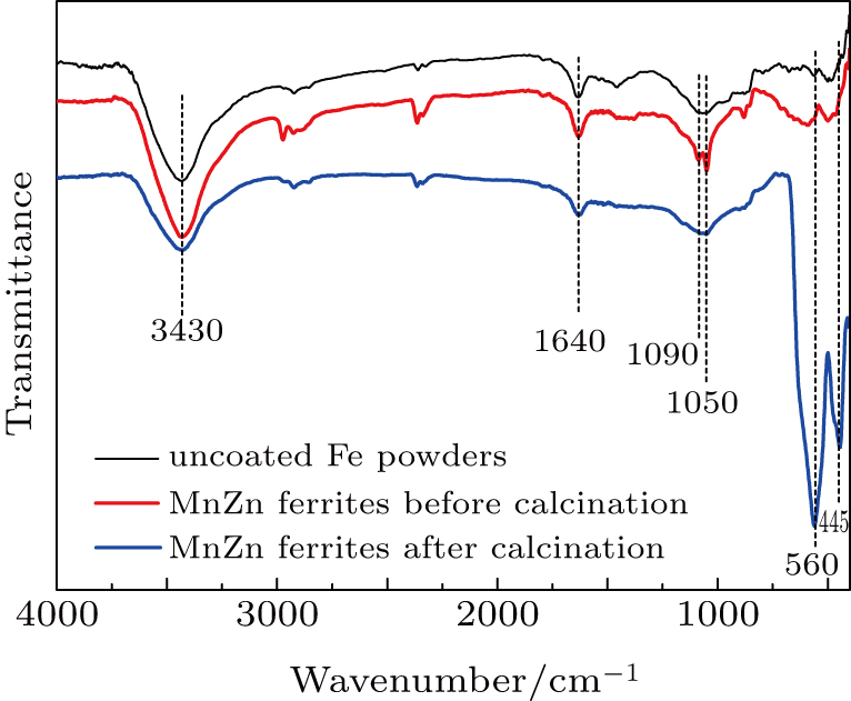
Fig. 4. The FTIR spectra of the Fe powders with MnZn ferrites coating before and after calcination at 500 °C compared with that taken from the uncoated powders.

Figure 5(a) shows the cross-sectional bright field TEM of the powder coated with MnZn ferrite. The upper region belongs to the Pt protection layer and the bright region between the Pt layer and iron powder is the ferrite coating. The coating structure is compact and exhibits satisfactory adhesion to the powder, although voids can still be observed. Figure 5(b) presents the high-angle annular dark-field (HAADF) imaging, and the dark region between the Pt layer and the base metal is the coating layer. The EDS mapping results in Fig. 5 reveal that the insulation layer is composed of Fe, Mn, Zn, and O. Combined with XRD and FTIR data, the insulation coating mainly consists of MnZn ferrite and oxides.

Fig. 5. (a) Cross-sectional bright field TEM image of the coated powder and (b) HAADF image and EDS mappings showing the distribution of Fe, Mn, Zn, and O.
3.3. Loss separation analysis

Without considering the excess loss, the total core loss Pcv can be expressed by the equation[7] where Ph is the hysteresis loss and Pe is the eddy current loss. The Ph plays a dominant role in the core loss at low frequencies and can be significantly reduced by high-temperature annealing. At high frequencies, the eddy current loss Pe is the main core loss since it is proportional to the square of the frequency and can be expressed as[23,24] where k1 is constant, Bmax is the maximum magnetic flux density, f is the frequency, d is the thickness of the sample, and ρ is the electric resistivity.

The insulation coating is the leading technique to minimize the eddy current loss Pe, which includes the interior eddy currents Pintra of iron powders and currents flowing in the entire cross-section Pinter between adjacent powders. The intra-particle Pintra and inter-particle eddy current losses can be calculated as follows:[25] where dFe is the diameter of iron powders, Bm is the maximum flux density, f is the frequency, is the density of iron powders, rFe is the resistivity of iron powders, and rbulk are the density and electrical resistivity of the bulk SMCs. The effective diameter of the SMCs, deff, for the sample with cross-sectional area Aq can be expressed as[25] The geometrical coefficient β can be calculated by[26] where w and h are the width and height of the SMC, respectively.

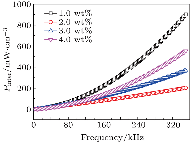
Figure 6 depicts the calculated inter-particle eddy current losses as a function of frequency based on Eqs. (3) and (4), which follows the same trend with the total core losses Pcv as shown in Fig. 1. The SMCs with 2.0 wt% MnZn ferrite coating exhibit minimum inter-particle eddy current losses resulted from the uniform and complete insulation coating, which effectively restricts the eddy currents flowing in the interior of the magnetic powders.

Fig. 6. The inter-particle eddy current losses as a function of frequency for the samples with different contents of MnZn ferrites.
3.4. Correlating the contents of ferrite coatings with the performance of the SMCs

The changes of Pcv and for the samples with different contents of MnZn ferrites (Fig. 1) can be explained as follows: when the MnZn ferrites content is 1.0 wt%, the insulation coating is thin and thereby its electrical resistivity is low, leading to relatively high Pcv and . An optimized Pcv is obtained for the sample with 2.0 wt% MnZn ferrites due to uniform and complete insulation coating. As the insulation content increases, the coating thickness and the corresponding resistivity follow the same trend. However, Pcv also increases which can be attributed to the increment of hysteresis loss. During the compaction process, the samples with more insulation contents are prone to crack and generate more pores. The pores act as air gaps that provide pinning sites for the movement of domain walls, which leads to increased Pcv and reduced .

4. Conclusion

Fe powders have been coated with MnZn ferrites via one-step sol–gel method. The effects of different MnZn ferrite contents on the performance of the SMCs have been investigated, and optimized magnetic properties have been achieved for the SMCs with 2.0 wt% MnZn ferrite due to the decrement of inter-particle eddy current losses based on loss separation. The microstructure and composition distribution of the coating layers have been carefully demonstrated according to the combined FTIR, TEM, and EDS mapping results. A uniform and compact coating layer composed of MnZn ferrite and oxides is obtained, and the cross-sectional thickness of ferrite layer is around .

Reference
[1] Shokrollahi H Janghorban K 2007 J. Mater. Process Technol. 189 1
[2] Wu Y Q Bitoh T Hono K Makino A Inoue A 2001 Acta Mater. 49 4069
[3] Ślusarek B Jankowski B Sokalski K Szczygłowski J 2013 J. Alloy. Compd. 581 699
[4] Gutfleisch O Willard M A Brück E Chen C H Sankar S G Liu J P 2011 Adv. Mater. 23 821
[5] Sunday K J Hanejko F G Taheri M L 2017 J. Magn. Magn. Mater. 423 164
[6] Taghvaei A H Shokrollahi H Janghorban K 2009 J. Alloy. Compd. 481 681
[7] Xie D Z Lin K Lin S 2014 J. Magn. Magn. Mater. 353 34
[8] Svensson L Frogner K Jeppsson P Cedell T Andersson M 2012 J. Magn. Magn. Mater. 324 2717
[9] Strečková M Medvecký Ĺ Füzer J Kollár P Bureš R Fáberová M 2013 Mater. Lett. 101 37
[10] Hemmati I Madaah-Hosseini H R Kianvash A 2006 J. Magn. Magn. Mater. 305 147
[11] Yaghtin M Taghvaei A H Hashemi B Janghorban K 2013 J. Alloy. Compd. 581 293
[12] Wu C Huang M Q Luo D H Jiang Y Z Yan M 2018 J. Alloy. Compd. 741 35
[13] Zhao G L Wu C Yan M 2016 J. Magn. Magn. Mater. 399 51
[14] Zhao G L Wu C Yan M 2016 J. Alloy. Compd. 685 231
[15] Zhao G L Wu C Yan M 2015 IEEE Trans. Magn. 51 2002904
[16] Wang W J Zang C G Jiao Q J 2013 Chin. Phys. 22 128101
[17] He L H Deng L W Luo H He J Li Y H Xu Y C Huang S X 2018 Chin. Phys. 27 127801
[18] Li J Peng X L Yang Y T Ge H L 2017 J. Magn. Magn. Mater. 426 132
[19] Zhang S Y Li S J Luo X W Zhou W F 2000 Corros. Sci. 42 2037
[20] Shen S C Ng W K Zhong Z Y Dong Y C Chia L Tan R B H 2009 J. Am. Ceram. Soc. 92 1311
[21] Colomban P 1989 J. Mater. Sci. 24 3002
[22] Rodrigues A P G Gomes D K S Araújo J H Melo D M A Braga R M 2015 J. Magn. Magn. Mater. 374 748
[23] Zhao Y W Zhang X K Xiao J Q 2005 Adv. Mater. 17 915
[24] Brauer J R Cendes Z J Beihoff B C Phillips K P 2000 IEEE Ind. Appl. 36 1132
[25] Taghvaei A H Shokrollahi H Janghorban K Abiri H 2009 Mater. Des. 30 3989
[26] Lauda M Füzer J Kollár P Strečková M Bureš R Kováč J Baťková M Baťko I 2016 J. Magn. Magn. Mater. 411 12