Plasma electrolytic liquefaction of sawdust
Jiang Cong-Cong1, Liu Shi-Yun2, Feng Zhe1, Fang Zhi2, Zhang Xian-Hui1, ‡, Mei Dan-Hua2, §, Xi Deng-Ke1, Luan Bing-Yu1, Wang Xing-Quan3, Yang Si-Ze4
Fujian Provincial Key Laboratory of Plasma and Magnetic Resonance, Institute of Electromagnetics and Acoustics, Department of Electronic Science, College of Electronic Science and Technology, Xiamen University, Xiamen 361005, China
College of Electrical Engineering and Control Science, Nanjing Technology University, Nanjing 211816, China
School of Physics and Electronic Information; Institute of Low Temperature Plasma Technology, Gannan Normal University, Ganzhou 341000, China
Department of Electronics, College of Information Engineering, Zhengzhou University, Zhengzhou 450001, China


† Corresponding author. E-mail: zhangxh@xmu.edu.cn danhuam@126.com

Project supported by the National Natural Science Foundation of China (Grant No. 51877184).

Abstract

As a renewable carbon resource, biomass can be converted into polyols, aromatic hydrocarbons, alkanes, and other products by traditional catalytic liquefaction method, which has been widely used in production and life. The efficient development and utilization of biomass energy will play a very positive role in solving the problems of energy and ecological environment. A way of combining the plasma electrolysis with traditional catalytic liquefaction realizes the efficient liquefaction of sawdust, which provides a new liquefaction way for traditional biomass conversion. In this experiment, the effects of solution composition, catalyst content and power supply on solution resistance and liquefaction rate are analyzed. It is found that solution composition and catalyst content have a great influence on solution resistance. The results show that the liquefaction rate is highest and the resistance is smallest when the solution resistance is 500 Ω. The liquefaction rate is greatly affected by the solution temperature, and the solution temperature is determined by the output power between the two electrodes. The output power includes the heating power of the electric field and the discharge power of the plasma. We measure the electric potential field distribution in the solution and the plasma power. It is found that the output power between the two poles increases nonlinearly (from 0 to 270 W) with time. In two minutes, the electric field heating power increases from 0 to 105 W and then decreases to 70 W, while the plasma power increases from 0 to 200 W. It is well known that in the first 70 seconds of the experiment the electric field heating is dominant, and then the plasma heating turns into a main thermal source. In this paper, plasma electrolysis and traditional catalytic liquefaction are combined to achieve the efficient liquefaction of sawdust, which provides a new way for biomass liquefaction.

1. Introduction

Biomass is defined as the renewable organic material originating from plants including wood wastes, energy crops, aquatic plants, agricultural crops, and their derivatives, as well as the municipal and animal wastes. It is considered as potential renewable sources of fuels and chemical feedstock due to the characteristics of its abundance and neutrality for respective carbon emissions.[1]

The biomass liquefaction is a promising technology for the conversion of biomass into bio-chemicals and liquids bio-fuels. So far, the methods employed for liquefaction mainly include the solvent–catalytic liquefaction,[2,3] hydrothermal liquefaction,[4] and the supercritical/subcritical liquefaction.[5] The applications of hydrothermal liquefaction and the supercritical/subcritical liquefaction are restricted by the strict operation conditions, which normally require high temperature and high pressure to obtain supercritical/subcritical fluid for the post-processing of liquefaction. The solvent-catalytic liquefaction is an effective method to convert biomass into fuels, however this process normally requires unsatisfactorily long time to reach an acceptable yield of bio-fuels.[6,7] For this reason, the development of an alternative process under the mild conditions is very important for the economic viability of biomass liquefaction.

Recently, our research group has combined plasma electrolysis in the presence of sulfuric acid as the catalyst with traditional polyethylene glycol 200 (PEG 200) and glycerol co-solvent liquefaction to achieve a fast liquefaction of pine sawdust.[8] Previous experiments[8] show that the plasma electrolysis liquefaction (PEL) process is also that of solid macromolecules (sawdust) decomposing into small molecules (liquids and gases), which is directly related to the change of solution resistance in the process of PEL. Therefore, it is necessary to carry out further research. Apart from the solution temperature, the power of discharge plasma also directly affects the sawdust liquefaction process. Therefore, it is necessary to analyze the relationship between the power of discharge plasma and liquefaction rate.

2. Experiments
2.1. Materials

Pine sawdust (Fujian) was dried for 12 h in an oven set at 105 °C, then crushed, sieved, and separated using 40–80 meshes. The sifted sawdust was placed in a desiccator at room temperature. The water content, ash content, acid insoluble lignin, cellulose, and alpha cellulous content of the biomass feedstock pine sawdust are summarized in Table 1. The C, H, O, and N contents of the pine sawdust were determined by an elemental analyzer (Vario EL III) and the results are also shown in Table 1. The PEG 200, glycerol, acetone, and concentrated sulfuric acid used in this experiment were all analytically pure.

Table 1.

Compositions of pin sawdust (%).

.
2.2. Experimental setup

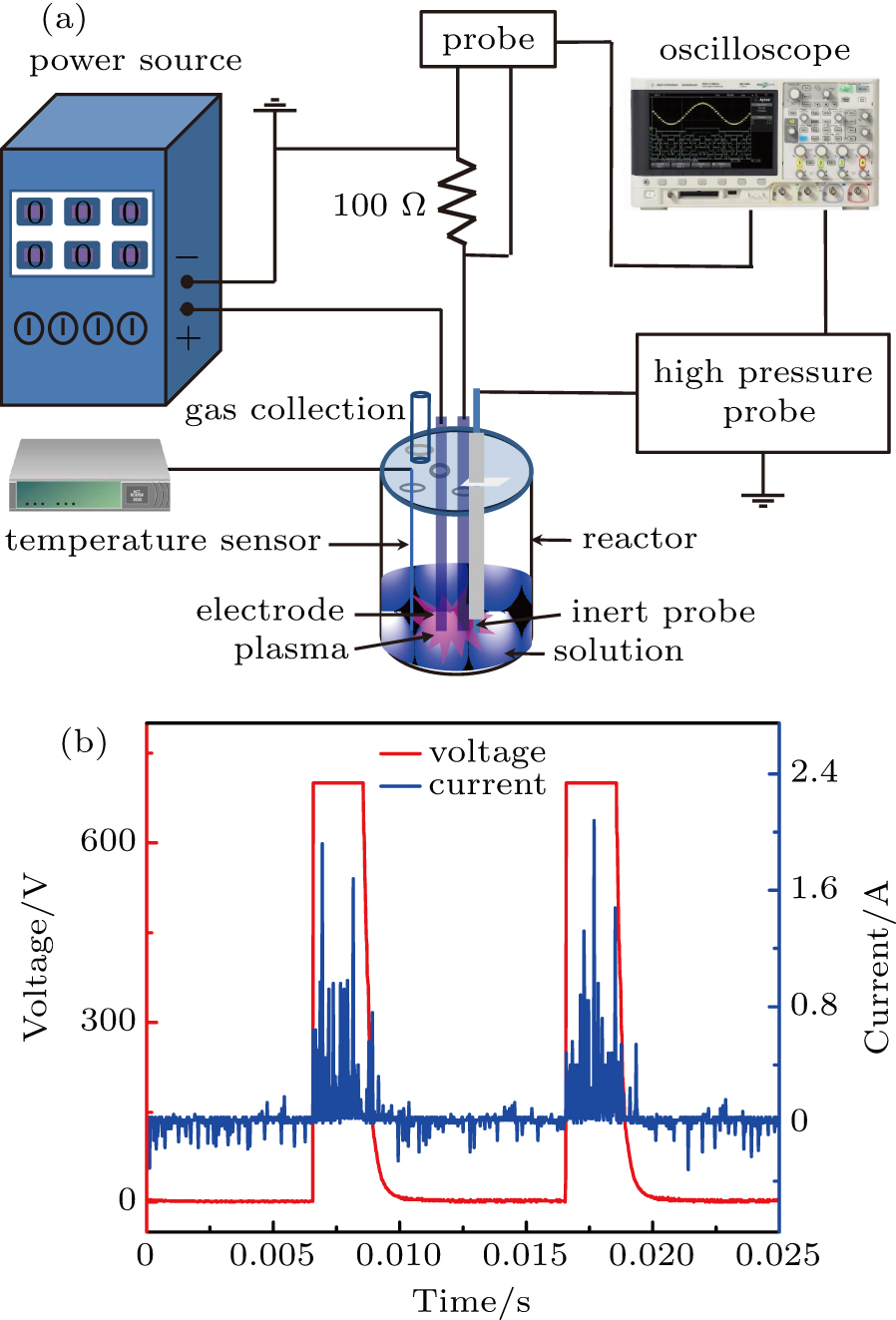
Figure 1(a) shows the overall schematic diagram of the experimental setup. The liquefying device mainly consists of a DC pulse power supply, a plasma reactor, and a condensation system. The prepared sawdust raw material, the blend solvent of PEG 200 and glycerol as well as the catalyst sulfuric acid were mixed together in a cylindrical quartz container (volume 100 ml). Two tungsten rods (height 150 mm, diameter 1.6 mm, purity 99.9%) were placed in the mixed aqueous slurries with a depth of 17 mm and connected to the pulsed high-voltage DC power supply (MAO-6, China) directly acting as the electrodes with a gap of 10 mm. In the liquefaction process, the output voltage, duty cycle, and frequency were set to be in the range of 0 V–2000 V, 5%–80%, and 50 Hz–2000 Hz, respectively. A typical discharge waveform of the DC power supply was revealed in Fig. 1(b). A thermal detector (Pt-1000, 0 °C–1700 °C, Maser AC) was used to measure the temperature of the solution. The produced gases were flowed through an iced-cold trap to split entrained droplets and then were gathered into a gas bag for further analysis. The liquefied products were separated by filtration through vacuum filter. The filter residue was washed by acetone and repeat filtrated until the filtrate was colorless. The filtrate from acetone washing was rotary-steamed to remove acetone, after that the left liquid was mixed with the first filtrate to obtain the liquid product. The gaseous products were analyzed by a gas chromatography (Agilent Micro3000-GC) equipped with a thermal conductivity (TCD) and a flame ionization detector (FID), while the liquid samples were analyzed by gas chromatography with mass spectrometric (QP 2010 Plus, Japan, column: REX-5 MS). For the detection and identification of the generated products the initial temperature of the GC oven was 50 °C, holding time was 5 min; temperature increased to 280 °C at a rate of 10 °C/min then held for 150 min. A spectrometer (HR2000+) was used to record the emission spectra and to identify the excited reactive species formed in the PEL process. The filter residue after acetone washing was dried into solid residue in an oven at 105 °C for 12 h, collected and weighted,. The liquefaction yield (%) is expressed as where f represents the liquefaction yield, m1 is the mass of the raw sawdust material that was used in the experiment, and m2 is the mass of the solid residue. The field emission electron microscopy and SEM spectroscopy (Hitachi S4800 SEM Japan) were used to investigate the properties of the residue. Additionally, the power optimization parameters denoted duty ratio 30%, frequency 200 Hz, and input voltage 710 V, and solution optimization parameters denoted PEG 200 = 24 mL, glycerol 7 mL, catalyst content , biomass 5 g. All analysis was carried out under optimal conditions.

Fig. 1. (a) Schematic diagram of liquefying device, and (b) voltage and current curve diagram.
2.3. Method of analysis

To study the effect of the variation of the solution impedance on the plasma electrolytic liquefaction of sawdust, the copper rods with a purity of 99.9% (diameter, 1.0 mm) were used to replace the tungsten electrodes and connected to the impedance analyzer (Agilent HP4192a) to identify the resistance of the aqueous slurries. Besides, two tungsten wires each with a diameter of were used as the electrodes and the electrical potential between the electrodes were measured with an oscilloscope (Tektronix TDS 2024B).

3. Results and discussion
3.1. Plasma liquefaction characteristics

Based on the previous studies of biomass liquefaction,[9,10] the experimental parameters are specified as follows: the amount of sawdust is 5 g, PEG 200 and glycerol are used as co-solvent with a volume of 31 mL and the amount of the catalyst, sulfuric acid was . To evaluate the influence of the electric field between the two electrodes on the ionic ionization in the plasma discharge process, the applied voltage and current are simultaneously measured by using a digital oscilloscope with a 1:1000 high voltage probe and a Tektronix P2220 current probe. The results are shown in Fig. 2. Clearly, the voltage range can be divided into four stages, namely U1, U2, U3, and U4. In the first stage U1 (0 V–230 V), the current increases linearly with the voltage increasing, which is consistent with Ohmʼs law. This phenomenon reveals that the solution shows a pure resistance property at the first stage. Further increasing the voltage shifts the reaction to the U2 phase (230 V–410 V). In this stage, the electrons and ions in the solution are accelerated quickly due to the increased kinetic energy and result in a nonlinear relationship between the discharge current and the applied voltage. As the voltage continually increases to 710 V, the unstable gas discharge near the electrodes is formed due to the gasification of the reaction solution, which is caused by the avalanche effect of a large number of electrons driven by electronic and electric field acceleration after atomic collision and abundant heat. This stage is regarded as the transition stage (U3:410–710). In this stage, generated gas covers the electrodes and results in the decrease of current due to the lower gas conductivity; meanwhile, this stage is always accompanied by a large quantity of heat radiation and gas emission. Further increasing the voltage until the stage U4 (710 V–750 V) is reached, unstable discharge mode shifts to the stable arc discharge with expanding the avalanche breakdown area. The cathode is completely wrapped with gas breakdown during the gas discharge and leads to the formation of the stable discharge stage with a current of 0.2 A. At this stage, abundant reactive free radicals from the gas discharge enter into the solution.[11]

Fig. 2. Relation between voltage and current during PEL discharge.

In the process of voltage increasing from 0 V to 750 V, a large amount of white smoke is formed on the mixed aqueous slurries and accompanied by a slight explosion. After that the smoke recedes, an arc discharge is clearly observed close to the cathode, the solution near the cathode begins to boil and is followed by the formation of small gas bubbles. Later, the flash becomes larger and brighter, and boiling becomes violent, which is accompanied by splashing of the solution on the inner wall of the reactor and generating the white fog. From the above analyses, the process of sawdust liquefaction can be represented by the plasma electrolysis process,[12,13] thus the input voltage in this case is valued to be 710 V.

3.2. The influence of solvent on the solution resistance in PEL

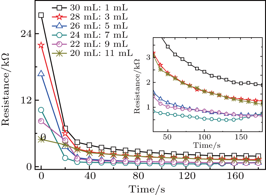
In order to investigate the effect of the liquefaction agent on the resistance in PEL process, the volume ratio of the co-solvent PEG 200 and glycerol is varied from 30:1 to 20:11 (mL:mL) with a total volume of 31 mL unchanged. The input voltage, the 98% sulfuric acid volume, and the biomass feedstock sawdust amount are all kept constant, they are 710 V, and 5 g, respectively. In the PEL process, the aqueous slurries are characterized by pure resistivity. This may be explained by the fact that the positive and negative ions in the solution move in the opposite directions, resulting in the static charge of the volume element being zero. Obviously, the initial solution resistance remarkably decreases from 27 kΩ to 5 kΩ with the amount of glycerol increasing from 1 mL to 11 mL and it gradually decreases with the continuous increase of electrolysis time as shown in Fig. 3. It is interesting to note that the smallest resistance is obtained at an optimal solvent ratio of 24:7 (V:V) and electrolysis time of 130 s. This might be attributed to the fact that the polarity of glycerol is larger than that of polyethylene glycol 200, which is of benefit to the rapid liquefaction of sawdust to degrade cellulose and lignin producing a large amount of small molecule chemicals at first stage, resulting in a decrease of the solution resistance. While further increasing the amount of glycerol and electrolysis time would lead to the polymerization, which means that the small molecules in the solution would gradually aggregate into large-molecule compounds, and contribute to the increase in the solution resistance.

Fig. 3. Plots of resistance versus time for different co-solvent ratios of PEG 200 to glycerol in PEL process (with catalyst content , biomass 5 g).
3.3. The influence of catalyst content on solution resistance

In order to determine how the content of sulfuric acid can affect the solution resistance and the temperature of solution in the PEL process of sawdust, the experiment is conducted under various quantities of catalyst in a range from to , with the following parameters fixed: sawdust of 5 g, input voltage of 710 V, frequency of 200 Hz, duty ratio of 30% and the ratio of PEG 200 and glycerol of 24:7 (V:V) as shown in Fig. 4. Clearly, the increasing of the content of sulfuric acid can significantly reduce the solution resistance and it gradually declines with reaction time increasing in the PEL process. It is noteworthy that the lower initial resistance is favorable for the rise of the solution temperature. A similar result was reported by Genki et al. that increasing the solution temperature is of benefit to the igniting of the plasma discharge.[14] Results show that the resistance of the solution drops rapidly when the content of the concentrated sulfuric acid is (pH= 1.87). After 20-s plasma discharge treatment, the value of the solution resistance is almost the same as that of the added of 350- sulfuric acid, and the corresponding solution resistance is 400 Ω–500 Ω. There is no significantly effect of the catalyst content on the liquefaction process, hence the content of catalyst in this case is fixed at .

Fig. 4. Plots of resistance and temperature versus time in PEL process (with PEG 200 = 24 mL, glycerol 7 mL, biomass 5 g).
3.4. Analysis of electrolytic characteristics of PEL
3.4.1. The effects of frequency on liquefaction of sawdust

The frequency of power supply used in the plasma electrolysis ranges from 50 Hz to 2 kHz. The experimental results indicate that the change of frequency has no significant influence on the solution resistance. As the homogenized solution used in this research shows the characteristic of pure resistance, no obvious relationship between the frequency and the solution resistance is observed. Therefore, the frequency of power supply is fixed at 200 Hz.

3.4.2. Effect of duct cycle on liquefaction of sawdust

The power duty ratio used in the experiment can be adjusted from 5% to 80%, and the corresponding pulse width changes from 2.5×10⁻³ s to 40×10−3 s. Since the H+ ionsʼs acceleration time in the solution is proportional to the pulse width, the duty ratio is an essential factor in the PEL process. Figure 5 shows the dependence of solution resistance on the power supply duty ratio at a fixed input voltage of 710 V, frequency of 200 Hz and the solvent amount of PEG 200/glycerol of 24 mL/7 mL. Obviously, increasing the duty cycle initially reduces the solution resistance and reaches a minimum value of 1600 Ω when the duty ratio is 30%, beyond which the resistance of solution is gradually enhanced when the power supply duty ratio further increases up to 50%. This result might be attributed to the fact that the catalytic effect of glucoside bonds in cellulose in sawdust is best when an acceleration time of H+ ion is 15×10−3 s and a corresponding power supply duty ratio is 30%. Hence, in this case the frequency and the duty ratio of the pulsed power supply are fixed at 200 Hz and 30%, respectively.

Fig. 5. Plots of solution resistance versus time for various contents of sulfuric acid, in PEL process (at frequency 200 Hz, and constant voltage 710 V).
3.4.3. The influence of potential and radicals on PEL of sawdust

The plasma electrolysis technology is used to liquefy the biomass feedstock sawdust. This experiment is conducted at room temperature and atmosphere pressure, where the input voltage is 710 V, frequency and duty ratio of power supply are 200 Hz and 30%, respectively, and the amount of solvent PEG 200, glycerol, and catalyst (sulfuric acid) are 24 ml, 7 ml, and , individually.

The reason for using 710 V as an input voltage is that the liquefaction process under plasma discharge mainly occurs in the U4 stage, when the cathode is covered by the generated gaseous products and the discharge current can keep steady at 0.2 A with the input voltage increasing from 710 V to 750 V. To analyze the effect of the potential in the solution and radicals generated through the plasma discharge on the PEL process of sawdust, the temperature of oil bath is set to be 225 °C initially followed by heating the aqueous slurries which includes sawdust, PEG 200, glycerol, and catalyst, 98% sulfuric acid. It can be seen in Fig. 6 that 100% liquefaction yield is reached in 10 min by using the conventional liquefaction method. The possible mechanism is that the excited H+ ions generated form H2SO4 could react with the oxygen atom on the glucosidic bond in the cellulose, and then the protons on the carbon site of glucosidic bond are transferred, resulting in the rupture of this bond as well as the degradation of cellulose. Meanwhile, cellulose is one of the key components of the pine sawdust (about 44%), which is very hard to liquefy. Thus, the treatment of cellulose plays a key role in the liquefaction process. The rate of biomass liquefaction using plasma electrolysis is considerably higher than that using a conventional liquefaction process. Specifically, the PEL treatment shows not only a higher liquefaction rate but also a higher energy efficiency, which just needs 140 s to achieve a 100% liquefaction yield at an energy cost of 0.00642 kWh, while the conventional liquefaction treatment requires 90 min at an energy consumption of 1.6 kWh. The comparison between the sawdusts before and after treatment by PEL is shown in Fig. 7.

Fig. 6. Comparison between curves of the liquefaction yield in PEL liquefaction process and conventional liquefaction process.
Fig. 7. Pictures of sawdust before and after treatment by PEL, showing (a) raw material of sawdust, (b) aqueous slurries without any treatment, liquid sample treated by PEL for (c) 60 s, (d) 120 s, and (e) 180 s.

In the plasma electrolysis liquefaction process, the increase of the solution temperature is due mainly to its being heated by the potential drops on the solution resistance and the discharge plasma. When the input voltage keeps constant, the potential of the solution will increase with the resistance decreasing, and then, the resistance power can increase according to the following equation: meanwhile, the solution temperature will be affected by the plasma discharge. Hence, it is important to investigate the synergy effect of the thermal-effect produced by the solution resistance and plasma discharge.

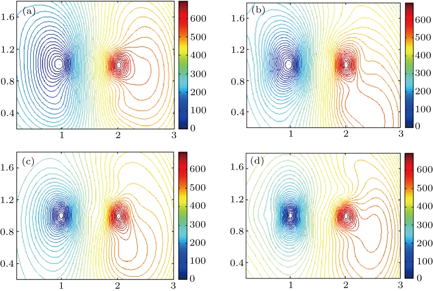
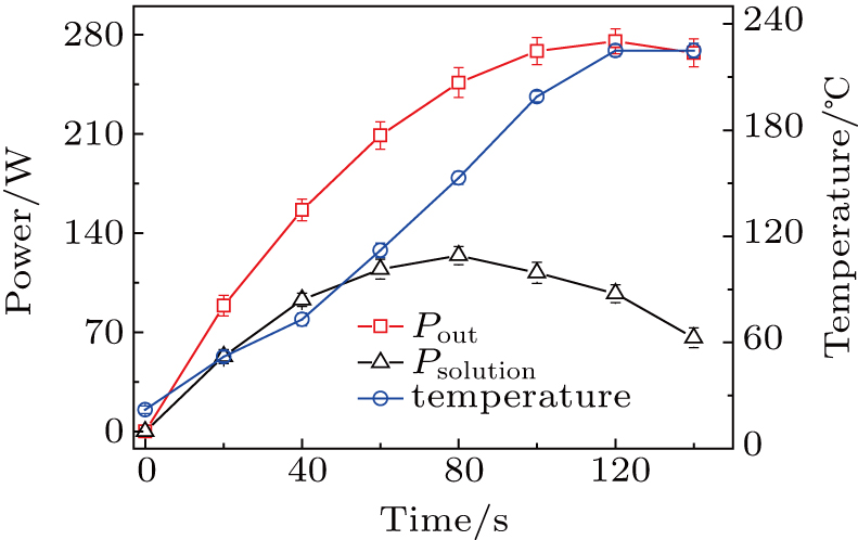
In order to detect the electrical potential in the solution, two tungsten wires each with a diameter of are used as the probes in the operating conditions with an input voltage of 710 V, a duty ratio of 30% and the frequency of the power supply is fixed at 200 Hz. In addition, the software MATLAB is used to simulate the distribution of the electrical potential in the solution as a function of plasma electrolytic time, and the results are shown in Fig. 8. It is clearly seen that the equipotential line density near the cathode in the PEL process of sawdust increases significantly, which means that the potential drop near the cathode is remarkably enhanced with the solution resistance decreasing, while no obvious change of the potential drop close to the anode is observed. This result reveals that the intensity of the plasma electrolytic liquefaction of sawdust near the cathode is significantly enhanced with the plasma discharge time increasing. In addition, the increase of electrical potential in the solution and the decline of the solution resistance over the liquefaction time lead to the increase of the heating power caused by the solution resistance. The heating power generated by the solution resistance at different liquefaction times could be determined from Eq. (2). The total output power provided by the power supply equals the sum of the heating power and the discharge power in the solution. Therefore, the discharge power, heating power and the total output power are displayed in Fig. 9. Clearly, the initial stage of electrolysis is mainly based on the solution resistance heating. When the solution temperature reaches a value above 100 °C, the discharge power increases gradually. Afterward, the PEL process is mainly driven by the plasma discharge heating.

Fig. 8. Equipotential line distributions for different reaction times: (a) 20 s, (b) 60 s, (c) 120 s, (d) 150 s.
Fig. 9. Curves of the solution power, total output power provided by the power supply, and the solution temperature versus time for PEL process of sawdust.
4. Product characterization
4.1. Gas product analysis

The H2 and CO were the main gas products from the PEL process. The mole percentage of H2 and CO are 97.7% and 1.8%, respectively. A smaller quantity of hydrocarbons (CH4, C2H6, and C2H4) are also detected with a total mole percentage of 0.5%. This phenomenon indicates that the H2-rich gas is obtained in the PEL process. The components of the gas production from the PEL process are similar to these obtained in the traditional catalytic liquefaction process, but the mole percentage of each component is totally different.[15]

4.2. Optical diagnostics of PEL process

Optical emission diagnostics (OES) is carried out to understand the formation of the reactive species in the PEL process. Figure 10 shows the typical emission spectrum of the PEL process. The spectrum is clearly dominated by the lines of OH, CH, and C2. The OH at 309 nm mainly originates from the reaction of Eq. (3), which indicates that the H and OH radicals are formed.[16] The CH at 431 nm is mainly formed by the reaction of Eq. (4).[17] In this reaction, CH2 mainly results from the dissociation of CH4. Therefore, it is suggested that hydrocarbons (i.e., CH4 and C2H4) and H2 are formed in the PEL process, which can be confirmed by the distribution of gas products. The CH2 and CH3 radicals from CH4 dehydrogenation are not observed in the spectrum. C2 Swan band system ( , ) at 516 nm may be from the solid carbon in the residue.[18]

Fig. 10. Typical emission spectrum of PEL process.
4.3. Liquid product analysis

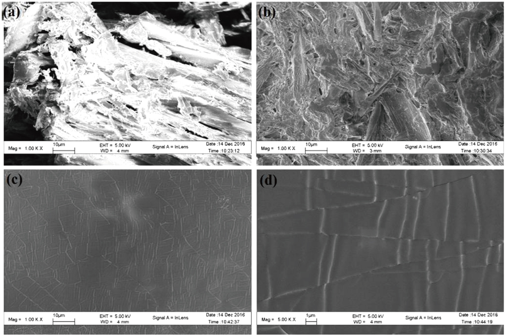
The main components of pine sawdust are lignin, cellulose, and total cellulose, which are mainly composed of polysaccharides. Among these substances, cellulose is a linear chain (glycosidic bond)-linked polysaccharide (molecular weight higher than 5×10⁴) composed of hundreds and thousands of β ( ) linked D-glucose units.[19] More than 200 components are detected in the liquid products from the PEL process, which can be divided into five categories: (i) organic acids, such as acetic acid, levulinic acid, propionic acid, gluconic acid, etc.; (ii) alcohols and ketones, such as 2-propanol, butanol, 2-hydroxy-4-methylacetophenone, etc.; (iii) sugar, such as D-glucopyranose, cellobiose, etc.; (iv) ester, such as butyl levulinate, glucosyl acetate, trimethyl-135-benzenetricarboxylate, etc.; (v) phenols, containing monophenols (such as phenol) and polyphenols (such as m-diphenol). The categories (i)–(iv) products are mainly derived from direct or indirect oxidative degradation of cellulose, while the (v) product is mainly from the oxidative degradation of lignin. The main components are basically the same as those obtained by the traditional liquefaction method.[20] The electron microscopy is used to analyze the raw material sawdust, solid residues and liquefied products as shown in Fig. 11. It can be seen that the sawdust composed of cellulose has an obvious loose block structure before being liquefied. After being liquefied, the block structure in the residues become distinctly tight and the size is also reduced; while the block structure in the liquefied product completely disappears and dense powder is observed.

Fig. 11. Electron microscopy scan micrograph of (a) 1000 times magnification of sawdust, (b) 1000 times magnification of solid residues, (c) 1000 times magnification of bio-oil, and (d) 5000 times magnification of bio-oil, prepared under standard parameters.

In addition, the infrared spectrum is also used to analyze the chemical properties of the sawdust liquid products and solid residues as shown in Fig. 12. Clearly, many peaks are found in a range of 1800 cm−1–800 cm−1, which are mostly characteristic absorption of structures such as carbonyl, ether bond and aromatic nucleus.[21] A strong aromatic hydroxyl absorption peak appears at 3400 cm−1 (–OH/–NH),[21] indicating that the wood chips and products are rich in aromatic hydroxyl species. The 2865 cm−1 (–CH3) is a methylene group and a methyl group in aliphatics and alkanes. Comparing the three curves, these products should be produced during liquefaction.[22] The peak at 1742 cm−1 (–C =O) mainly appears in the liquid product, indicating that a large quantity of aldehydes, ketones, acids, esters and other compounds are formed during liquefaction.[22] The carbon-carbon double bond in benzene ring, 1655 cm−1 (–C =C), mainly appears in the wood chips, which corresponds to the polysaccharide in the wood chips.[23] 1245 cm−1 (–CH) corresponds to the methine group on the aromatic derivative, which can be mainly seen in the residues.[24] The 1012 cm−1 (aromatic ring) corresponds to the benzene ring in aromatic compounds, mainly in residues and raw materials.[24] 13

Fig. 12. Infrared spectrum of wood chips, liquefied products, and residues.
Fig. 13. GC spectra of gases.

The liquefied products are complex and difficult to separate, but the content of nitrogen and sulfuric are low. At present, the bio-oil is mainly used for combustion, power generation or biomass adhesives, molded materials, foaming materials, etc.[25,26] For the combustion, the high calorific value of the liquefied product needs to be calculated. The calculation formula is as follows: The high calorific value (HHV) of the sawdust is 17.99 MJ/kg based on the data in Table 1. The elemental compositions of the liquefied products and the solid residues are analyzed by elemental analyzer, and the results are shown in Table 2. It can be seen that the C and H contents of liquid products both increase, while the oxygen content lowers. The decrease of oxygen content of the liquefied product results from the de-oxidation reactions that occur in the liquefaction processes, such as dehydration, decarbonylation and decarburization reaction, etc. Through calculation, the high heating value is obtained to be 22.27 MJ/kg, higher than that of wood. From Table 2, the C and H contents of solid residues both decrease, and the oxygen content increases, which leads to a lower high calorific value (HHV) of 11.51 MJ/kg than that from raw material sawdust.

Table 2.

Compositions of liquid product and solid residual (mole ratio%).

.
5. Conclusions

In the PEL experiment, we find that the solution resistance first decreases and then increases slightly. This process is consistent with that in which cellulose, hemicellulose, and lignin are first decomposed into small molecule compounds, and then polymerized into compounds with larger molecular weight. The results show that the change of solution resistance is consistent with the liquefaction rate, which can be used as a new method to calculate biomass liquefaction. By measuring the resistance heating power and the output power between the two poles, it is found that the electric field heating power is dominant in the first 70 seconds, and then the discharge plasma heating is the main thermal source. At the later stage, the liquefaction rate of biomass is significantly improved. But the initial electric field heating can effectively increase the solution temperature, which is conducive to the generation of discharge plasma. So, the PEL of sawdust is a synergistic process of solution resistance heating and plasma heating. In addition, the liquefaction products in PEL are analyzed. It is found that liquid products mainly consist of aldehydes, ketones, acids and esters, which come from cellulose, hemicellulose, and lignin. Gaseous products produced by discharge plasma mainly consist of H2, CO, CH4, and other gases.

Reference
[1] Agar D Wihersaari M 2012 Biomass Bioenergy 44 107
[2] Demirbaş A 2000 Energy Convers Manag. 41 633
[3] Xu C Etcheverry T 2008 Fuel 87 335
[4] Song C 2002 Catal. Today 77 17
[5] Yin S Dolan R Harris M Tan Z 2010 Bioresour. Technol. 101 3657
[6] Cheng S D’Cruz I Wang M Leitch M Xu C 2010 Energy Fuels 24 4659
[7] Br S Kim J 2015 Energy 80 64
[8] Xi D Zhou R Zhou R Zhang X Ye L Li J Jiang C Chen Q Sun G Liu Q 2017 Bioresour. Technol. 241 545
[9] Naik S N Goud V V Rout P K Dalai A K 2010 Renew. Sust. Energ. Rev. 14 578
[10] Yamada T Ono H 2001 J. Wood Sci. 47 458
[11] Lyerokhin A Nie X Leyl A Matthews A Dowey S J 1999 Surf. Coat. Technol. 122 73
[12] Wang L S Pan C X Cai Q Z Wei B K 2007 Acta Phys. Sin. 56 5341 in Chinese
[13] Gu W C G H Chen H Chen G L Feng W R Zhang G L Yang S Z 2007 Acta Phys. Sin. 56 2337
[14] Saito G Nakasugi Y Akiyama T 2014 J. Appl. Phys. 116 123303
[15] Demirbas A 2009 Energy Convers Manag. 50 2239
[16] Li Y L Zhao C Kwok W M Guan X Zuo P Phillips D L 2003 J. Chem. Phys. 119 4671
[17] Denysenko I B Xu S Long J D Rutkevych P P Azarenkov N A Ostrikov K 2004 J. Appl. Phys. 95 2713
[18] Ito H Kawamura Y 2008 J. Non-Cryst Solids. 354 3267
[19] Klemm D Heublein B Fink H P Bohn A 2005 Angew. Chem. Int. Ed. 44 3358
[20] Saha B C Iten L B Cotta M A Wu Y V 2005 Process Biochem. 40 3693
[21] Ye L Zhang J Zhao J Tu S 2014 Bioresour. Technol. 153 147
[22] Zhang H Ding F Luo C Xiong L Chen X 2012 Ind. Crops & Products 39 47
[23] Zhang T Zhou Y J Liu D H Petrus L 2007 Bioresour. Technol. 98 1454
[24] Chen F Lu Z 2009 J. Appl. Polym. Sci. 111 508
[25] Lucia A Argyropoulos S Adamopoulos L Gaspar A R 2007 Acs. Symposium 954 2
[26] Liu L F Li H Q Lazzaretto A Manente G Tong C Y Liu Q B Li N P 2017 Renew. Sust. Energ. Rev. 69 912