


Generation of wide-bandwidth pulse with graphene saturable absorber based on tapered fiber
Cite this Article
Zhang Ren-Li, Wang Jun, Liao Mei-Song, Li Xia, Guan Pei-Wen, Liu Yin-Yao, Zhou Yan, Gao Wei-Qing. Generation of wide-bandwidth pulse with graphene saturable absorber based on tapered fiber. Chinese Physics B, 2019, 28(3): 034203 
Permissions
Generation of wide-bandwidth pulse with graphene saturable absorber based on tapered fiber
† Corresponding author. E-mail:
Project supported by the National Key Research and Development Program of China (Grant No. 2018YFB0504500), the National Natural Science Foundation of China (Grant Nos. 61475171, 61705244, 61307056, and 61875052), and Natural Science Foundation of Shanghai, China (Grant Nos. 17ZR1433900 and 17ZR1434200).
Abstract
Wide-bandwidth pulses were generated with a dispersion-managed erbium-doped passively mode-locked fiber laser based on a graphene saturable absorber. The graphene saturable absorber was composed of a tapered fiber deposited with graphene fabricated by liquid-phase exfoliation. The output pulse had a 3-dB bandwidth of 13.6 nm, which is the widest spectrum ever achieved with graphene-tapered-fiber saturable absorbers.
1. Introduction
Ultrafast fiber lasers have a wide range of applications in various fields, such as optical frequency metrology, medicine, and precise materials processing.[1–5] The passive mode-locking technique is one of the main approaches to generating ultrashort pulses. Several methods have been reported for realizing passive mode locking, such as nonlinear polarization rotation (NPR),[6,7] nonlinear optical loop mirror (NOLM),[8,9] and semiconductor saturable absorber mirror (SESAM).[10,11] Compared with NPR and NOLM, the SESAM method offers better stability and self-starting performance.[10] However, the drawbacks of SESAM, such as a low damage threshold and a small response bandwidth, have restricted the applications of SESAM in passively mode-locked fiber lasers, thereby promoting researches into new saturable absorbers (SA) such as carbon nanotubes and graphene.[12–14]
Since 2009, when graphene, a new type of two-dimensional (2D) material, was successfully used for the first time as a new SA in ultrafast optics,[15] it has attracted significant attention in the field of passive mode-locking technology owing to its fast recovery time, wide response bandwidth, and easy fabrication.[16–18] In particular, compared to other SAs, such as carbon nanotubes and SESAM, graphene shows obvious advantages in the realization of ultrafast pulses because of the properties of broadband response.[12] In addition to the above advantage, SAs based on graphene can be realized with various integration methods for fiber devices, which cannot be applied with SESAMs.[19–23] Among these integration methods, the ones based on evanescent field interaction, such as graphene-tapered-fiber (GTF) SAs, are popular in the research of graphene mode-locking devices owing to their high damage threshold, long interaction length, and convenient manufacture.[24,25]
Several researches on mode-locked fiber lasers using GTF SAs have been reported. These studies have various concerns, such as multiwavelength operation,[26] tunable-bandwidth mode-locked fiber lasers,[16] SAs with tunable modulation depth[27] and high output power.[28] However, among these works, there are few reports on wide-bandwidth mode-locked pulses. It is generally known that a large abnormal cavity dispersion limits the generation of pulses with wide spectra and narrow pulse durations. To obtain pulses with better performance, the net cavity dispersion must be further reduced to near zero.[29,30] However, the decrease in the cavity dispersion causes poorer laser stability,[31] thereby leading to higher requirements for the performance of SAs, such as a larger modulation depth and shorter recovery time.[32] To date, the widest bandwidth of the output spectrum based on the GTF SA is 10 nm, realized with a net cavity dispersion of −0.094 ps2.[16] However, in the above report, no further investigation was conducted on the bandwidth of the output spectrum realized with smaller net cavity dispersion. Therefore, for the GTF SA, an interesting question is what is the best output performance that a GTF-SA-based mode-locked fiber laser can achieve with intracavity dispersion management? To answer this question, in this work, a GTF-SA-based erbium-doped passively mode-locked fiber laser with small net cavity dispersion was constructed. To calculate the net cavity dispersion accurately, the dispersion of the tapered fiber was taken into consideration, and it was calculated using finite-element analysis. With the compensation of the intracavity dispersion, the net cavity dispersion was reduced to −0.0317 ps2. A wide-bandwidth mode-locking pulse was generated with a 3-dB bandwidth of 13.6 nm, which is the widest spectrum obtained with a GTF-SA-based erbium-doped mode-locked fiber laser.
2. Fabrication and characterization of GTF SA
where lt is the total taper length, lf is the effective length of the fused zone, and d is the initial fiber diameter, which was set to 125 μm. By fitting the measured data with Eq. (1 ), lt and lf can be determined to be 42.586 mm and 3.634 mm, respectively. The measured data and fitting result are shown in Fig. 2 . Then, by using finite-element analysis, the dispersion of different diameters of the tapered fiber was calculated. Together with the fitting result of the tapered fiber shape, the dispersion distribution at 1550 nm along the z-axis of the tapered fiber was obtained, as shown in Fig. 2 . By integrating the calculated dispersion along the z-axis, the total dispersion of the tapered fiber can be estimated to be −0.00264 ps2, which is approximately 2.8 times that of SMF-28. Although the total dispersion of the tapered fiber is small, it cannot be neglected if the cavity dispersion is close to zero.
The modulation depth of graphene is proportional to its layer number. Multilayered graphene offers a larger modulation depth and is more suitable for ultrafast pulse generation than a single-layered one.[12,33,34] A simple and effective method for obtaining multilayered graphene is liquid-phase exfoliation (LPE),[35–37] which was applied in this experiment. During the preparation, 200 mg of graphite powder was mixed with 40-ml N-methyl pyrrolidone (NMP) and sonicated for 1 h. To deal with the material heating in the process of ultrasonication, the whole process was carried out in a circulating water bath with a temperature of 3 °C. Then, the mixture was centrifuged for 90 min with a rotary speed of 3000 rpm to separate graphene and large agglomeration. After the centrifugation, the upper liquid was collected as graphene dispersion.
Raman spectroscopy was employed to verify the effectiveness of the graphene preparation. The graphene dispersion was dropped on a slide glass substrate and dried at 50 °C as the test sample. The Raman spectrum of the sample was measured at an excitation wavelength of 488 nm. The result is shown in Fig.
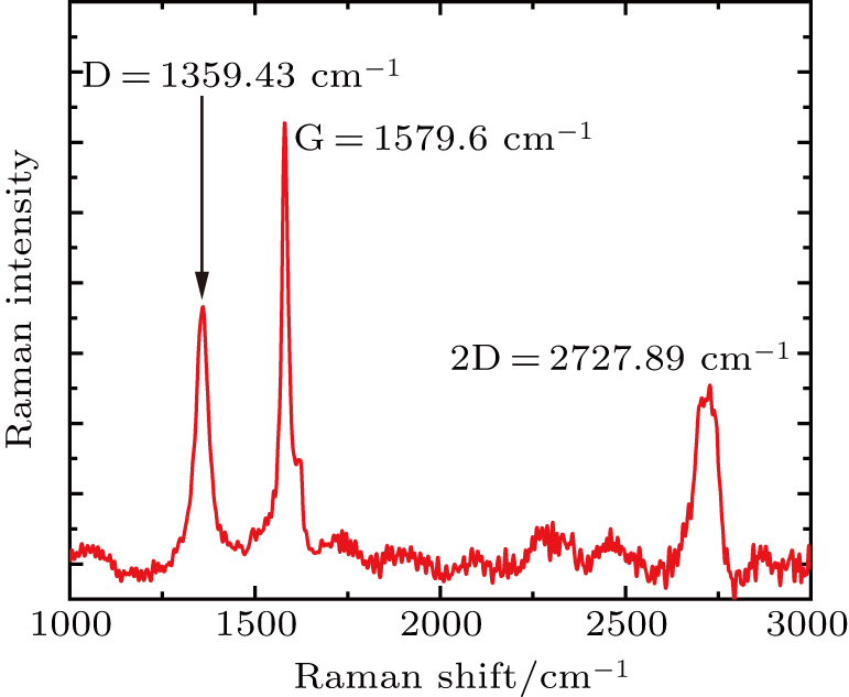 | Fig. 1. Raman spectrum of the graphene prepared by LPE method in the experiment. |
The tapered fiber was fabricated by an oxyhydrogen-flame stretching method with a segment of single-mode fiber (SMF-28). The waist diameter of the tapered fiber was approximately 3 μm. The intrinsic loss was measured as 0.01 dB at the wavelength of 1550 nm.
For better cavity dispersion management, the detailed group velocity dispersion (GVD) distribution of the tapered fiber was calculated. Initially, the shape of the tapered fiber was measured using an optical microscope. The shape of the tapered fiber can be expressed with the formula[39]
 |
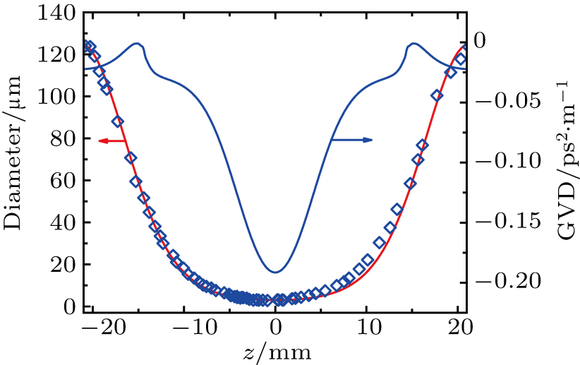 | Fig. 2. Shape of the tapered fiber (blue hollow squares: measured diameter; red solid line: numerical fitting) and the calculated dispersion distribution at 1550 nm along the z-axis of the tapered fiber (blue solid line). |
To deposit the graphene onto the tapered fiber, the waist part of the tapered fiber was immersed in the graphene dispersion and an approximately 100-mW continuous wave laser at 1560 nm was injected into the tapered fiber. Because of the optical tweezer effect and light-induced swirl and convection, a graphene nanosheet was trapped and deposited onto the tapered fiber.[40] After about 20 min, the deposition was completed. To guarantee a high enough modulation depth of the graphene SA, graphene nanosheets were deposited on the tapered fiber as much as possible, thereby leading to a large insertion loss. The insertion loss of the tapered fiber was measured as approximately 6.3 dB at 1560 nm. Using a microscope, it can be seen that the graphene nanosheets were deposited unevenly on the surface of the tapered fiber waist with a distribution length of about 150 μm.
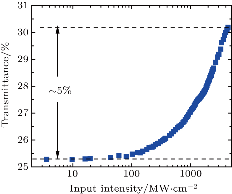
The nonlinear optical absorption characteristic of the GTF SA was investigated using a balanced twin-detector system. The laser source used in the experiment was a commercial passively mode-locked erbium-doped fiber laser with a pulse width of ∼ 200 fs and a central wavelength of 1557 nm. The measured result is shown in Fig.
 | Fig. 3. Nonlinear absorption curve of the GTF SA. |
3. Experimental setup
A passively mode-locked fiber laser was constructed, as shown in Fig.
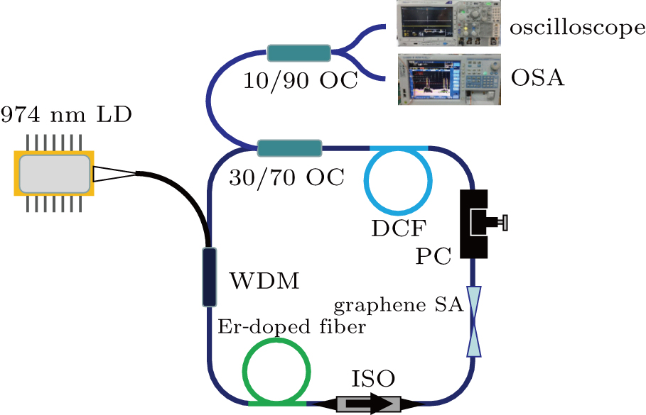 | Fig. 4. Experimental setup of the mode-locked fiber laser using the GTF SA. |
4. Results and discussion
where ΔλN is the wavelength offset from the N-th order of the Kelly sideband position to the central wavelength, λ is the central wavelength, c is the speed of light in vacuum, D is the dispersion parameter of the laser cavity, L is the cavity length, and τ is the pulse width. The calculation was conducted with the second-order (λ2 = 1581.36 nm) and the third-order (λ3 = 1587.96 nm) Kelly sideband positions. With simple derivation, the pulse width can be expressed as follows:
where Δλ2 and Δλ3 represent the wavelength offsets from the second- and the third-order sidebands to the central wavelength, respectively. Based on Eq. (3 ), the pulse width was calculated as 213 fs. The time–bandwidth product was 0.354. Because the third-order dispersion was not taken into account, the actual pulse duration might be slightly larger than the value deduced here. In view of the reported works, as a mode-locking result obtained with an actual SA, 213 fs is a short pulse width.[43–50]
When the pump power reached 67.5 mW, the laser output began to shift from continuous wave (CW) laser to Q-switched mode-locking pulses. When the pump power was increased to 79.8 mW, a CW-mode-locking pulse was obtained. The laser maintained the fundamental mode-locking working state until the pump power reached 116.4 mW. A further increment in pump power caused the mode-locked laser to work in the bound-soliton mode-locking regime. The relationship between the pump power and output power is shown in Fig.
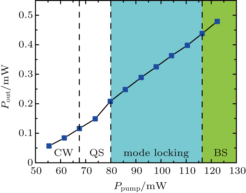 | Fig. 5. Output power vs. pump power (CW: continuous wave regime, QS: Q-switched mode-locking regime, and BS: bound-soliton regime). |
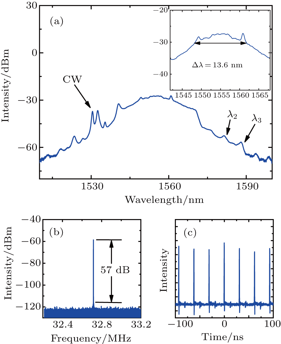
As shown in Fig.
 | Fig. 6. Output pulse characteristics: (a) output spectrum with 3-dB bandwidth of 13.6 nm at a pump power of 110.5 mW, (b) RF spectrum, and (c) output pulse train. |
Owing to the small output power and limitation of the experimental condition, the pulse duration could not be measured directly by the autocorrelator used in the experiment. To have a more complete understanding of the output performance, the pulse width was calculated based on the Kelly sideband position of the output spectrum. If the third- and higher-order dispersions are ignored, the position of Kelly sideband can be expressed as[42]
 |
 |
The generation of the wide-bandwidth pulse can be attributed to the small net dispersion of the laser cavity. In the experiment, the length of DCF was set to be constant. The length of SMF-28 was changed to control the net cavity dispersion. As the SMF-28 became shorter, the net cavity dispersion gradually approached zero and the output spectrum became wider. When the length of SMF-28 was shortened to 3.84 m, the widest spectrum with 13.6-nm bandwidth was achieved. Further shortening the SMF-28 would narrow the spectrum bandwidth. The failure of the realization of stable mode-locked pulse with a 3-dB bandwidth wider than 13.6 nm may be because of the limitation of the modulation depth of the GTF SA.
The output performances of previous reports on erbium-doped mode-locked fiber lasers using GTF SAs are listed in Table
| Table 1. Output performances of erbium-doped mode-locked fiber lasers incorporating GTF saturable absorbers. . |
5. Conclusion
In this study, an erbium-doped passively mode-locked fiber laser based on GTF SA was demonstrated. With proper dispersion management, an output pulse with a 3-dB bandwidth of 13.6 nm was obtained, which is the widest spectrum ever achieved from a GTF SA-based mode-locked fiber laser. The output pulse had a repetition rate of 32.72 MHz and a signal-to-noise ratio of 57 dB.
Reference
| [1] | |
| [2] | |
| [3] | |
| [4] | |
| [5] | |
| [6] | |
| [7] | |
| [8] | |
| [9] | |
| [10] | |
| [11] | |
| [12] | |
| [13] | |
| [14] | |
| [15] | |
| [16] | |
| [17] | |
| [18] | |
| [19] | |
| [20] | |
| [21] | |
| [22] | |
| [23] | |
| [24] | |
| [25] | |
| [26] | |
| [27] | |
| [28] | |
| [29] | |
| [30] | |
| [31] | |
| [32] | |
| [33] | |
| [34] | |
| [35] | |
| [36] | |
| [37] | |
| [38] | |
| [39] | |
| [40] | |
| [41] | |
| [42] | |
| [43] | |
| [44] | |
| [45] | |
| [46] | |
| [47] | |
| [48] | |
| [49] | |
| [50] | |
| [51] | |
| [52] |