Boundary scheme for lattice Boltzmann modeling of micro-scale gas flow in organic-rich pores considering surface diffusion
Zuo Hong1, 2, Deng Shou-Chun1, †, Li Hai-Bo1
State Key Laboratory of Geomechanics and Geotechnical Engineering, Institute of Rock and Soil Mechanics, Chinese Academy of Sciences, Wuhan 430071, China
University of Chinese Academy of Sciences, Beijing 100049, China


† Corresponding author. E-mail: scdeng@whrsm.ac.cn

Abstract

We propose a boundary scheme for addressing multi-mechanism flow in a porous medium in slip and early transition flow regimes, which is frequently encountered in shale gas reservoirs. Micro-gaseous flow in organic-rich shale involves a complex flow mechanism. A self-developed boundary scheme that combines the non-equilibrium extrapolation scheme and the combined diffusive reflection and bounce-back scheme (half-way DBB) to embed the Langmuir slip boundary into the single-relaxation-time lattice Boltzmann method (SRT-LBM) enables us to describe this process, namely, the coupling effect of micro-gaseous flow and surface diffusion in organic-rich nanoscale pores. The present LBM model comes with the careful consideration of the local Knudsen number, local pressure gradient, viscosity correction model, and regularization procedure to account for the rarefied gas flows in irregular pores. Its validity and accuracy are verified by several benchmarking cases, and the calculated results by this boundary scheme accord well with our analytical solutions. This boundary scheme shows a higher accuracy than the existing studies. Additionally, a subiteration strategy is presented to tackle the coupled micro-gaseous flow and surface diffusion, which necessitates the iteration process matching of these two mechanisms. The multi-mechanism flow in the self-developed irregular pores is also numerically investigated and analyzed over a wide range of parameters. The results indicate that the present model can effectively capture the coupling effect of micro-gaseous flow and surface diffusion in a tree-like porous medium.

1. Introduction

The accurate understanding of the fundamental flow mechanism of methane gas in complex micro/nanopores is crucial to the effective exploitation of unconventional reservoirs, the strata of which is associated with kerogen networks and organic matter. The unconventional reservoirs, such as shale reservoirs and other tight sandstone gas reservoirs, contain abundant micro-scale and nanoscale pores, the sizes of which vary in a wide range on a micro-scale from 2 nm up to 100 nm,[1] typically presenting multi-scale networks of pores. The non-Darcy flow, such as slip flow and early transition flow,[2] dominates in these multi-scale pore networks. In kerogen-rich pores, the coupled micro-scale effects and surface diffusion (induced by methane adsorption/desorption process) control the gas flows, involving a complex flow mechanism, while only the micro-gaseous flow exists in these inorganic pores in the absence of adsorption/desorption.

Despite its attracting significant research attention in recent years, the accurate flow mechanism of micro-gas in an organic-rich porous medium still has not been well addressed, because the existing models and parameters are geometry-dependent and not applicable to these irregular pores. Most of the current analytical models for micro-gaseous flow in organic/inorganic pores are limited to cases with simple geometries, such as tube and channel,[35] which are of limited applicability to shale reservoirs where complex irregular nanopores are ubiquitous. To our best knowledge, the multi-mechanism flow is still less understood, although some hypothetical models have been proposed to capture gas transport in organic nanopores considering surface diffusion.[3,4] Additionally, the experiment-based studies are less accurate due to the extremely low mass transport capability of shale and difficulty in controlling laboratory conditions.[69]

As a replacement or supplementary to experiments and theories, numerical simulation has become a promising and effective tool to research and reveal some micro-scale physical mechanisms which fall beyond the scope of experiments and theories. A variety of numerical models, such as molecular dynamics simulation (MD),[1013] direct simulation of Monte Carlo (DSMC),[14,15] lattice Boltzmann method (LBM),[16,17] and traditional computational fluid dynamics (CFD), have been widely applied to the studies of micro-gaseous flow. Due to expensive computational costs, MD and DSMC have extremely restricted applications on a macroscale. The traditional continuum-based CFD models are of limited applicability to the rarefied gas flows where continuum assumption breaks down (e.g., Kn > 0.1). The LBM, originating from the kinetic theory of molecules,[18,19] is a mesoscopic numerical model. It achieves considerable success in modeling the near continuum regime flows ( Kn < 0.1), and has been tried in previous studies to treat rarefied gas flows in transition flow regimes within straight channels.[2029] A series of LBM-based models with kinetic boundary schemes has been proposed to address micro-gaseous flow over curved surfaces in the slip and early transition flow regime.[3038] Karlin et al.[35] first proposed a discrete form of the completely diffusive reflection, which can be applied to curved walls, but some studies revealed that this boundary overestimates the slip velocity at the wall for micro-Poiseuille flow. Following Karlin et al.’s work, a combination form of diffusive reflection and bounce-back scheme (namely the DBB scheme), proposed by Luo et al.[34] and Chai et al. almost at the same time,[32] has been used to model micro-gaseous flow in complex pores. In the DBB scheme, the 1st-order[34] or 2nd-order velocity-slip boundary condition[32] was incorporated into the LBM model by choosing an appropriate combination coefficient. The studies of Tao and Guo et al. expanded the applications of the DBB scheme to micro-flows over spheres in slip and early transition regimes.[33,37,38]

To date, despite the fruitful achievements in predicting the micro-gaseous flow in slip and early transition flow regimes via LBM-based models, little attention has been paid to the LBM-based modeling of the coupled multi-scale and multi-mechanism flow. The strategies appearing in previous literature can be summarized into five categories in terms of LBM-based modeling for the micro-gaseous flow considering surface diffusion. In the first category, the Langmuir slip model is incorporated into the LBM.[3941] By using the non-equilibrium extrapolation scheme,[42] Fathi et al.[39] first developed an LBM-based boundary scheme to capture the multi-mechanism flow. Wang et al.[40] developed a similar boundary to account for the Langmuir slip model. In the boundary scheme of Wang et al., the strategies of Inamuro et al.[43] were used to handle the surface diffusion, and the slip velocity of free gas near to the wall was determined by a kinetic boundary scheme. However, extending their boundary scheme into inclined wall or curved wall was difficult for several reasons. Wang et al.[41] presented a new boundary scheme to take account of Langmuir slip boundary by utilizing the non-equilibrium extrapolation approach.[42] Again, only the cases with straight channels were validated and tested in their studies. In the second category, long-range forces are introduced into the LBM to consider gas adsorption/desorption and boundary slip (see Refs. [10], [39], [44], and [45] for details). In their studies, gas adsorption/desorption in organic pores was modeled by long-range forces between gas and wall, and the velocity-slip induced by micro-scale effect and rarefaction effect was simulated by kinetic boundary schemes. Nevertheless, the selection of some micro-parameters of long-range forces in these models, e.g., the interaction strength between gas and wall, wall’s density, is a challenging task. In the third category, some semi-analytical or analytical models are incorporated into the LBM.[4649] Chen et al.[46] proposed a generalized LBM model to simulate the flow through a representative elementary volume (REV) scale porous medium considering the Klinkenberg’s effect, based on the permeability correction in drag force, then an REV-scale LBM model was developed to approach the multi-mechanism flow in the reconstructed shale matrix.[47,48] In the fourth category, the surface diffusion is considered as a moving boundary.[5052] Ren et al.[50,53] developed the BSR or DBB boundary with a moving wall to study the coupling effect of micro-scale flow and surface diffusion, and the velocity of the moving wall equals the adsorbed-gas transport velocity. However, the constant pressure gradient was employed in their study to calculate the adsorbed-gas transport velocity, which did not reflect the real cases with complicated geometries. In the fifth category, the LBM and other numerical methods are coupled,[10,11] e.g., molecular dynamics.

As pointed out above, the LBM-based modeling for micro-gaseous flow considering surface diffusion in irregular organic-rich pores is still in its vacancy. In this study, a more accurate model is developed to address this issue and overcomes some existing defects. The rest of this paper is organized as follows. In Section 2, we introduce our LBM numerical model, LBM-based boundary scheme, algorithm to extend the present scheme to the cases involving irregular pores, and validations by benchmarking cases. In Section 3, we present extensive parametric studies on the micro-scale flow in a self-developed tree-like model considering surface diffusion. In Section 4, we draw some conclusions and point out the future research directions.

2. Lattice Boltzmann method and boundary conditions
2.1. D2Q9 single-relaxation-time LBM model

The lattice Boltzmann method is a mesoscopic numerical method for computational fluid dynamics. Using the multi-scale analysis developed by Chapman and Enskog, the Navier–Stokes equations can be recovered from the lattice Boltzmann equation. The expression of the lattice Boltzmann equation with external force can be given as follows:

where fi (x,t) is the particle distribution function, δt is the time increment, the term Ω(fi) on the right-hand side is the collision operator, and Fi is the external force in the i-th direction, which is defined as
with G being the external force in physical model.

This study adopts D2Q9 model to predict the gas flow through a porous medium. Its velocity directions are defined as: c0 = (0,0), c1 = (1,0), c2 = (−1,0), c3 = (0,1), c4 = (0,−1), c5 = (1,1), c6 = (−1,−1), c7 = (1,−1), and c8 = (−1,1).

Usually, the collision operator Ω(fi) is a nonlinear integral differential expression in terms of particle distribution function fi(x,t). The well-known linearized collision operator Ω(fi) is employed and expressed as[16]

where τs is the non-dimensional relaxation time, and is the equilibrium distribution function. The above lattice Boltzmann equation (Eq. (1)) combined with Eq. (2) is called the lattice Bhatnagar–Gross–Krook (LBGK) model, in which is given as
where wi is the weight, and cs is the sound speed of the lattice, and ρ and u are the density and velocity of the fluid, respectively.

The macroscopic quantities, e.g., density ρ, velocity u, and pressure p, can be expressed in terms of distribution function fi(x,t) as follows:

The relationship between kinematic viscosity v and relaxation time τs can be obtained to be
For the micro-scale flow, the widely recognized dimensionless parameter is the Knudsen number (Kn), which is defined as the ratio of the mean free path of gas molecules over the characteristic length. The relaxation time can be determined by the Knudsen number to be
where H is the characteristic length.

2.2. Boundary condition considering surface diffusion

The adsorbed methane gas and free gas are coexistent in organic-rich pores. An accurate description of the coupling process of micro-gaseous flow and surface diffusion induced by adsorbed gas is under development and still has a puzzle. The universally adopted Langmuir slip model[3941,54,55] is introduced to obtain the resultant slip velocity us at wall. It can be expressed as

where uw is the diffusion velocity induced by the surface diffusion, and ug is the slip velocity adjacent to the wall, and θ is the fractional coverage of adsorbed gas in thermal equilibrium.[56] The fractional coverage of adsorbed gas satisfies the following relation:
where b is the Langmuir constant, and p is the pressure of free gas.

We determine the diffusion velocity of adsorbed gas at wall with the strategies that combine the Maxwell–Stefan approach and Langmuir adsorption isotherm,[40] the effectiveness of which has been validated and confirmed by experimental and simulation studies. The diffusion velocity is expressed as[40]

where qsat is the Langmuir volume, ρads is the density of adsorbed gas, Ds is the Maxwell–Stefan diffusivity, M is the molecular weight of adsorbed gas, which equals 16 × 10–3 kg/mol for methane, and the definitions of b and p are shown in Eq. (7).

2.3. Self-developed boundary scheme considering surface diffusion

Note that three kinds of velocities are introduced into this study: the resultant slip velocity us, the slip velocity ug, and the surface diffusion velocity uw, as shown in Eq. (6). Next, we develop an LBM-based boundary scheme that combines with the aforementioned Langmuir boundary scheme (Eq. (6)) to capture the coupled effect of multi-scale and multi-mechanism flow in porous medium. Inspired by previous research,[40,41,50,51] in which the surface diffusion was regarded as a moving wall, in this work we employ the non-equilibrium extrapolation scheme[42] to accurately impose the prescribed velocity uw at the wall. The slip velocity ug can be determined by some LBM-based kinetic boundaries, e.g., the discrete Maxwellian (DM),[35] the combined bounce-back scheme and specular reflection (BSR),[57] and DBB.[31,32,35] We eventually employ the DBB boundary scheme[31] to introduce the 2nd-order velocity-slip boundary scheme into SRT-LBM for capturing micro-gaseous flow in regular/irregular pores in this study.

The idea of non-equilibrium extrapolation scheme is that the unknown distribution functions of boundary nodes are approximated with the results of adjacent fluid nodes. At time step t, after collision and streaming step, the unknown distribution functions of a boundary node xb are decomposed into two parts as follows:[58]

The equilibrium part is approximated with that of its adjacent fluid node as
where xf = xb + ci δt, and uw is the known diffusion velocity given by Eq. (8). The non-equilibrium part of the unknown distribution function is determined by that of its adjacent fluid node xf = xb + ci δt to be

After obtaining the unknown distribution functions of boundary nodes at time step t, the unknown distribution functions of adjacent fluid nodes at time step t + 1 can be provided by the collision and streaming of their adjacent boundary nodes, which can be expressed as

where indicates the post-collision distribution function of boundary nodes, and is expressed as
The halfway DBB boundary scheme developed by Chai et al.[31] is adopted in this study to determine the velocity slip ug at the wall. It can be expressed as
where represents the opposite direction of i, ris the combination parameter, and ρw and are the density and velocity of the wall, respectively. And K is the normalization factor to ensure mass conservation, and can be expressed as
where is the post-collision distribution function given as , and n is the wall’s normal vector.

Considering Eq. (14), for a static wall (namely, ), the DBB boundary scheme (Eq. (13)) can be simplified as

where represents the sum of post-collision distribution functions streaming toward solid nodes, and is the sum of the weights of outgoing distribution functions.

To include the 2nd-order slip boundary condition (e.g., ug = C1 λ (∂u/n)sC2 λ2 (2u/n2)s), the combination parameter r should be chosen as for the single-relaxation-time model[31]

where Δ = 1/H with H being the local characteristic length.

By combining Eqs. (15) and (12), we develop an LBM-based boundary scheme to implement the Langmuir slip boundary given by Eq. (6) in the LBM framework. This self-developed boundary scheme can be presented as

The boundary scheme (Eq. (17)) can be applied to the tree-like porous medium due to its independence of the normal vector of the wall.

2.4. Regularization procedure

To ensure that the present SRT-LBM scheme is more accurate and stable in the hydrodynamic regime, a regularization step, developed by previous studies,[5961] is embedded into this model to capture micro-gaseous flow at high Knudsen number. It filters out unnecessary higher-order contributions to non-equilibrium distribution functions to ensure that the non-equilibrium moments of the distribution functions satisfy the Hermite space.[60] The distribution functions are decomposed into the equilibrium and non-equilibrium parts as[60]

The non-equilibrium part can be converted into
where with δmn being the Kronecker delta function, , subscripts m, n are the dummy indexes which obey the Einstein’s summation convention, ci is the discrete velocity of D2Q9, just as shown in Subsection 2.1, and ckn is the n-th direction of discrete velocity ck.

The evolution equation for the SRT-LBM model after being regularized is given as

2.5. Local Knudsen number and local pressure gradient

For the micro-gaseous flow in a porous medium, the Knudsen number is a local geometry-dependent parameter and associated with space location due to the spatial variation of its influencing factors, such as temperature, gas pressure, local characteristic length, etc.

For the hard sphere molecule, the mean free path λ of gas molecule can be expressed as[36]

where m and ρ are the molecule mass and gas density, respectively, and σ is the molecule diameter.

With Eq. (21), the Knudsen number for ideal gas is given as

where R and T are the gas constant and temperature, respectively, NA is the Avogadro constant, Ploc and Hloc are the local pressure of gas and local characteristic length of porous medium, respectively, and they are determined by the following strategies. Equation (22) indicates that the product of local Kn, local pressure, and local characteristic length keeps constant for isothermal flow.

For pressure-driven micro-flows, the pressure gradient is also a space-dependent local parameter. To accurately capture surface diffusion and micro-scale flow along the surface, inspired by the research of Zhao et al.,[10,36] we propose a method to determine the local characteristic length and pressure gradient of free gas based on the following hypotheses: 1) the pressure variation of free gas along the transverse (or spanwise) direction can be neglected under an extremely low pressure difference at inlet and outlet; 2) the pressure gradient of free gas can be approximated by that of its nearest skeleton node of pore structures according to hypothesis 2); 3) the characteristic length of a fluid node equals that of its nearest skeleton node of pore structures, which can be reasonably accepted due to the definitions of the node’s characteristic length and skeleton of pore structures.

The detailed methods to approximately obtain the local characteristic length and pressure gradient of free gas are given below.

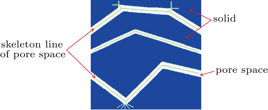
(I) The first step is to obtain the skeleton of pore structures. A thinning algorithm for digital patterns proposed by Zhang et al.[62] is employed in this study. It consists of two subiterations, aiming at deleting boundary points to obtain the skeleton of unitary thickness for random pore structures. A random porous medium and its skeleton line are shown in Fig. 1.
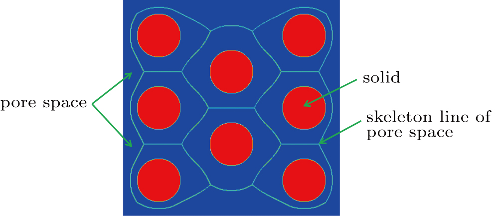
Fig. 1. A channel filled with circular cylinders and calculated skeleton line by Zhang’s algorithm: the porous media and skeleton line of unitary thickness.

(II) After obtaining the skeleton of pore structure, the local characteristic length of a skeleton point is determined by the maximal ball algorithm,[63] and then the local characteristic length of a fluid node is obtained under hypothesis 3).

(III) The pressure gradient of skeleton points is approximately obtained with difference approximation to partial derivatives, and then the pressure gradient of free gas is given by hypothesis 2).

With the local characteristic length of fluid nodes and local pressure gradient of free gas, we can easily implement the present boundary scheme in the LBM.

A few studies and numerical research[10,11,3942,44,5052] focused on the LBM-based modeling of multi-mechanism flow in micro/nanopores. However, most of them were only applied to a straight channel due to some limitations. The present scheme is built by coupling the non-equilibrium extrapolation scheme and halfway DBB boundary scheme, and later used to model multi-mechanism flow in a tree-like porous medium for its independence of the wall’s normal vector. The local Knudsen number for a fluid node and local pressure gradient along the skeleton line are also calculated to capture complex micro-flows along the irregular organic-rich pores. In addition, by considering viscosity correction and regularization procedure, the present model is capable of addressing high-Knudsen-number gas flows.

2.6. Model validation
2.6.1. Micro-gaseous flow in periodic microchannel

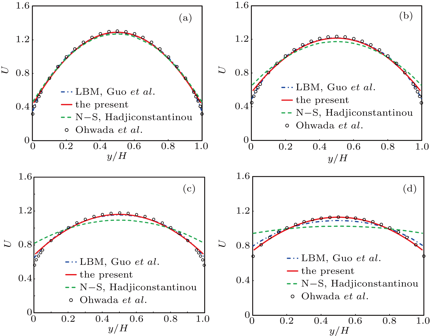
The micro-gaseous flow in a two-dimensional (2D) microchannel is employed to validate the proposed boundary scheme with Kn over a wide range. The gas flow is driven by a constant pressure gradient of ∂p/∂ x = 10–4, and the inlet and outlet are set as periodic boundary. The embedded Langmuir slip boundary (Eq. (17)) is imposed at the bottom and top walls with θ = 0. The slip coefficients of the 2nd-order velocity-slip boundary are chosen to be C1 = 1.1466 and C2 = 0.9757 for a full diffusive wall. The size is set to be Nx = 50 and Ny = 51, which is large enough to obtain grid-independence results. To compare with the results of Ohwada et al.,[64] micro-Poiseuille flows are carried out at with k = 0.1,0.2,0.4,1.0. The relaxation time in Eq. (5) is corrected as to capture rarefaction effects. The streamwise velocity profiles at four Knudsen numbers are presented in Fig. 2, where the dimensionless streamwise velocity U is defined as U = u/uave, with . Only slight differences are found between our results and those of Ohwada et al.,[64] although the discrepancies increase with the value of Kn increasing.

Fig. 2. Streamwise velocity profiles of micro-scale gas flow when Knudsen number varies in a wide range. Our numerical results are compared with those of Ohwada et al.,[64] Hadjiconstantinou et al.,[75] and Guo et al.[21] for (a) Kn = 0.1128, (b) Kn = 0.2257, (c) Kn = 0.4514, and (d) Kn = 1.1284.
2.6.2. Pressure-driven micro-gaseous flow in long microchannels

Gas flow driven by constant pressure gradient is the ideal case. However, the pressure-driven gas flow is more ubiquitous and significant in engineering applications. The micro-gaseous flow driven by pressure difference was modeled and validated in previous studies.[34,65] In this section, following the previous study,[65] we simulate the gas flow in a two-dimensional (2D) microchannel with height H and length L, and it is driven by a pressure difference between inlet pressure pin and outlet pressure pout. For isothermal micro-gaseous flow in the microchannel where the characteristic length of each fluid node is the height H, equation (22) can be further reduced into , where Knin and Knout are the Knudsen numbers at inlet and outlet, respectively, and p(x) is the pressure along the channel centerline. To compare with existing results, we choose two Knudsen numbers: Knout = 0.0194, 0.194.

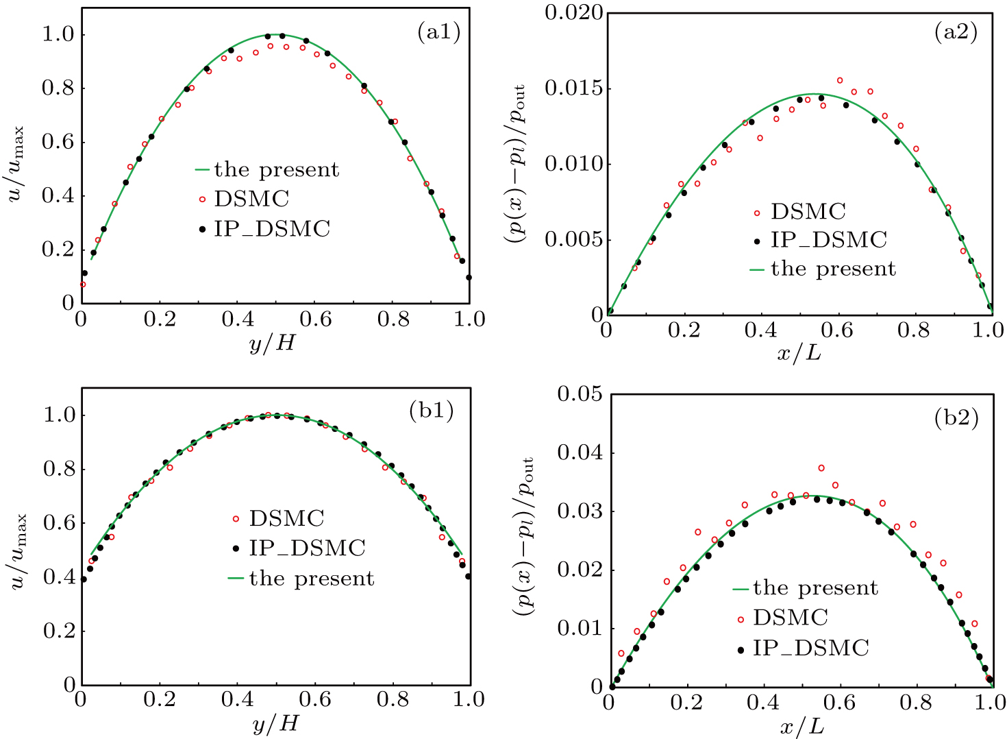
The size is set to be Nx = 2000 and Ny = 20 to ensure that the ratio of length over height is 100. The top and bottom walls are treated by the proposed boundary scheme, and the strategies of Verhaeghe et al.[34] are taken to address the pressure boundary at inlet and outlet. The outlet pressure pout is 1.0 / 3.0, and inlet pressure pin is set to be 1.4 / 3.0 for Kn = 0.0194 and 2.0 / 3.0 for Kn = 0.194. Figure 3 shows the normalized velocity u/umax at the outlet and dimensionless pressure deviation along the long microchannel when Kn = 0.0194, 0.194. The pressure deviation from linear pressure distribution pl along the streamwise direction is given as

where L = Nx presents the microchannel length.

Fig. 3. Normalized streamwise velocity profiles at outlet and non-dimensional pressure deviation along microchannel for (a) Kn = 0.0194 and (b) Kn = 0.194. Our numerical results are compared with results of Shan et al.[66]

In Fig. 3(a), the streamwise velocity and pressure deviation from linear pressure profiles match well with the results of IP-DSMC[66] when Kn = 0.0194. Figure 3(b) shows the corresponding results at Kn = 0.194, and good agreement between the present results and those of IP-DSMC,[66] which validates the effectiveness of the present scheme in predicting microchannel flow.

2.6.3. Validations of present boundary scheme

In the above two subsections, we verify that this boundary scheme is capable of modeling the micro-gaseous flow in slip and early transition flow regimes in a straight channel. In this subsubsection, we mainly check its accuracy and effectiveness in simulating the micro-scale gas flow considering surface diffusion. To include some existing results[40,41] for better comparison, we assume that uw = α ug, where 0 ≤ α ≤ 1. Under this assumption, equation (6) can be reduced to

And ug is determined by the 2nd-order velocity-slip boundary scheme to be
where u is the velocity of free gas.

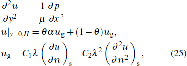
Then by combining Eqs. (24) and (23), the governing equation and boundary schemes for micro-gaseous flow in a single organic pore can be expressed as

where ∂ p/∂ x is the pressure gradient, and μ = ρ v is the dynamic viscosity.

The analytical solution of Eq. (25) can be obtained to be

where Kn = λ/H.

In this subsubsection, the present boundary scheme (Eq. (17)) is used to study multi-mechanism flow, including micro-scale gas flow and surface diffusion, and then it is further validated by our analytical solution (Eq. (26)). As stated by Lee et al.[67] and Li et al.,[65] the case with the infinitely long microchannel can be simplified into a periodic channel, which is reasonably used in this subsubsection.

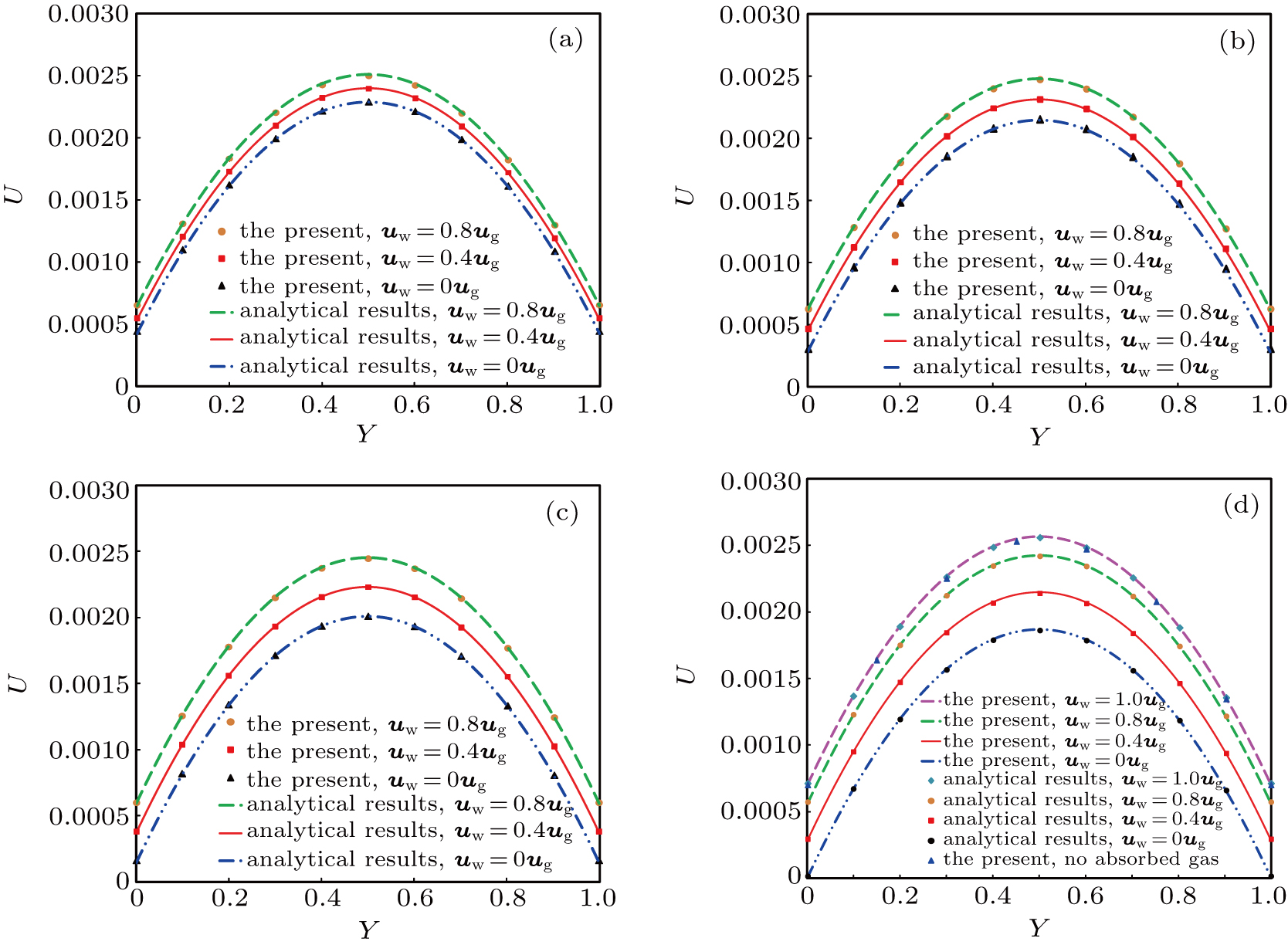
We first choose the case with Kn = 0.0729 and θ = 1.0 to make comparisons with the existing results.[40,41] The size is set to be Nx = 2 and Ny = 500 for the periodic microchannel in use, and it is proven that this mesh size satisfies the mesh-independence. Figure 4 shows the streamwise velocity profiles at outlet, where Y = y/H and U = u/umax with umax being the maximum velocity at outlet. The detailed comparisons between our numerical results, the results of Wang et al.[40] and Wang et al.,[41] and analytical solutions (Eq. (26)) are presented in this figure. It can be observed that the streamwise velocity profiles predicted by the present boundary match well with the analytical results, and it is also superior to the boundary schemes proposed by Wang et al.[40] and Wang et al.,[41] which cannot effectively predict the velocity at the wall. Wang et al.’s boundary scheme[40] tends to overestimate the streamwise velocity at large diffusion velocity, and Wang et al.’s boundary scheme[41] overestimates the velocity at the wall for all cases. It seems that the latter will introduce some unphysical velocity at the wall. To clearly show the differences, the velocities at walls predicted by four models are also given in Table 1, showing a maximum relative error of 1.85% between our results and analytical solutions, noticeably lower than those of Wang et al.[40,41] Specifically, our relative errors are about one order of magnitude smaller than those of Wang et al.[40,41] under the same conditions. For the internal micro-flows, the accurate capturing for the velocity at wall is critical for modeling the flow and permeability prediction. Moreover, Wang et al.’s model[40] is not applicable to the inclined channel (or curved wall) due to the limitations of Inamuro et al.’s boundary scheme.[43] In contrast, the present boundary scheme has a higher accuracy and the capability of addressing irregular pores, such as tree-like porous media in this study.
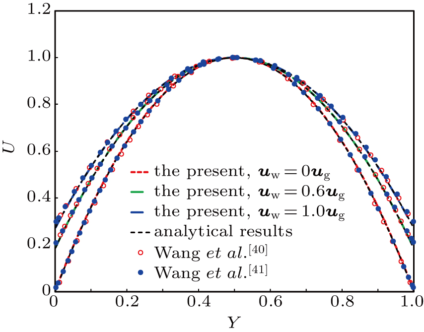
Fig. 4. Comparison among the non-dimensional velocity profile predicted by the present model, analytical result, and previous studies (Wang et al.[40] and Wang et al.[41]) when Kn = 0.0729 and θ = 1.0.

As is well known, the SRT-LBM model with bounce-back boundary will give rise to the viscosity-dependent unphysical issue when predicting velocity or permeability.[58,6870] Actually, it is not induced by the SRT-LBM model, but by the bounce-back boundary and discretization errors.[18,69] The bounce-back boundary generally introduces an unphysical velocity-slip at static wall, which is associated with τs and proportional to Δ2,[58] so it is responsible for this viscosity-dependent unphysical issue. It should be noted that this unphysical issue also exists in the MRT-LBM model if improper relaxation time τq is chosen. However, the present boundary scheme (Eq. (17)) is developed by combining the non-equilibrium extrapolation scheme and halfway DBB scheme. The fact that both of them accurately impose the prescribed velocity at wall ensures its effectiveness.

Table 1.

Normalized velocities at wall (us) predicted by different models, and the relative errors (in parentheses) between calculated results and analytical solutions when Kn = 0.0729 and θ = 1. The relative errors are calculated as %, with being the analytical solutions.

.

To further validate the proposed model, we carry out a series of validation cases with Kn (viscosities) and θ over a wide range. Our results are then compared with the analytical results from Eq. (26). The model and boundary schemes are the same as the above cases. Figure 5 shows our results and analytical results when Kn = 0.0729 with θ = 0.4–1.0 and α = 0.0–1.0. There is very little difference in the streamwise velocity between our results and the analytical results. A comparison of Fig. 5(a) to 5(d) indicates that as expected the us at wall decreases with the value of uw decreasing, and that small θ makes the effect of uw on us less significant due to the small percentage of adsorbed gas. Figure 5(d) presents the case with θ = 1.0, and the results when θ = 0.0 and us = ug are also included for comparison. It also demonstrates that the present boundary predicts well for micro-gaseous flow in the presence or absence of adsorbed gas, and that the Poiseuille flow in the continuum limit with no-slip boundary is also accurately recovered when θ = 1 and α = 0.

Fig. 5. Comparison between streamwise velocity profiles predicted by the present model and analytical results (Eq. (26)) when Kn = 0.0729 and (a) θ = 0.4, (b) θ = 0.6, (c) θ = 0.8, and (d) θ = 1.0.

In the following parts, several cases with Kn = 0.01–0.12, within which the micro-gaseous flow in tight gas reservoirs mainly falls, are carefully investigated to further validate the present model. Again, all settings are consistent with the above validations in this subsubsection except for Kn. Our results show good agreement with analytical results when micro-gaseous flow considering surface diffusion falls within slip and early transition flow regimes as shown in Table 2, where Ulbm and Uana are the sum of numerical and analytical streamwise velocities, respectively. It indicates that the maximum relative error between the present results and analytical solutions is less than 2% when Kn (viscosity) is in a wide range. Additionally, the diffusion velocity uw is accurately imposed on wall by the non-equilibrium extrapolation scheme, and with proper combination parameter r, the 2nd-order velocity-slip boundary scheme is employed to describe the micro-scale effect by halfway DBB scheme without introducing extra unphysical velocity. All these cases verify the accuracy and effectiveness of the present model.

Table 2.

Relative errors of streamwise velocity between our numerical results and analytical results (Eq. (26)) when Kn = 0.02, 0.05, 0.12, with θ = 0.2, 0.8 and α = 0.0–0.8. The relative errors = %, with Uana being the analytical solution.

.

In the following section, the micro-gaseous flow considering surface diffusion in self-developed tree-like porous medium is predicted by the present model.

3. Multi-mechanism flow in tree-like model

The real pore structures of shale and sandstone can be reconstructed by experimental methods (e.g., computed tomography and focused ion beam scanning electron microscopy), numerical approaches (e.g., quartet structure generation set), and theoretical methods.[53] The popular theoretical models[53] are the bundle-of-tubes models, regular lattice model, circular model,[71] tree-like model,[72] etc. Inspired by the Sakhaee–Pour and Bryant’s works,[72] we adopt a tree-like model (see Fig. 6) to represent shale matrix in the subsequent parametric studies.
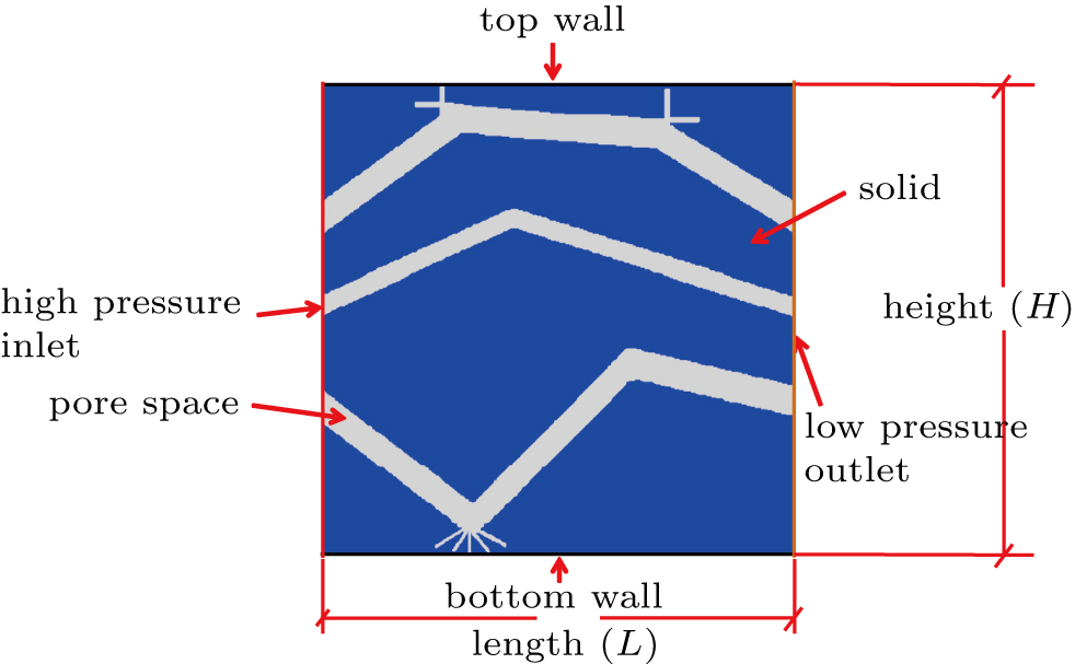
Fig. 6. Boundary conditions and geometry of tree-like model: left and right boundaries are pressure boundaries, and the present scheme (Eq. (17)) is imposed at pore surface.
Table 3.

Convention from physical units to lattice units (2D case).

.

In the above sections, all physical quantities (e.g., velocity, pressure) are non-dimensional parameters in lattice units, while all parameters have a specific physical unit in this section. Table 3 shows the convention from physical units to lattice units. Only time step increment dtphy is initially unknown in the physical system, and pressure platt is required to be determined in the lattice system. The other parameters in both physical and lattice systems are predetermined prior to computing. To determine the time step increment dtphy, we consider the relationship between the kinematic viscosity vphy in physical units and vlatt in lattice units

Equation (27) gives the value of dt (namely, dtphy), then Vr = Vphy and pr can be easily determined by Vr = dx/dt and pr = ρr · dx2/dt2, respectively. The detailed information is shown in Table 3. It is worth noting that the uw in Eq. (8) is generally calculated in physical units, and transformed into lattice units. This enables us to simplify the computation without directly converting several parameters from physical units to lattice units, such as the Langmuir volume qsat, Langmuir constant b, surface diffusivity Ds, etc.

Figure 6 illustrates the basic set-up of this numerical model, including the geometry and boundary conditions. The size is set to be Nx = 401 in length L and Ny = 401 in height H, which corresponds to the physical model with the initial size of 75 nm in length L and 75 nm in height H. The Zou and He’s boundary scheme[73] is employed to impose a pressure difference at inlet and outlet, then other boundaries are addressed with our carefully validated boundary scheme (Eq. (17)). In our cases, the gas pressure pout at outlet ranges from 10 MPa to 40 MPa with an initial pressure gradient of ∇p = 0.1 MPa/m along the streamwise direction at system temperature T = 338.7 K. The Langmuir parameters for the adsorbed gas are carefully chosen based on the Wang et al.’s data[40,48] summarized from existent collections predominately reported in the literature for shale. The detailed parameters and data are chosen as follows. The density of adsorbed gas at a given θ is set to be ρads = ρads,sat θ with ρads,sat being 340 kg/m3,[74] and the Maxwall–Stefan diffusivity Ds ranges from 10–8 m2/s to 10–5 m2/s. The Langmuir volume qsat is given as 1000–6000 mol/m3. The Langmuir constant b varies from 0.125 MPa–1 to 1.0 MPa–1.

In Subsection 2.5, we illustrated our strategies to obtain the local characteristic length Hloc and local pressure Ploc of free gas. The skeleton line of the tree-like model is shown in Fig. 7. Following Zhao et al.’s research,[10,36] we define the reference characteristic length Href and reference Knudsen number Knref to calculate the local Knudsen number for a fluid node. The reference characteristic length of the tree-like model can be given as

where ε is the porosity of the tree-like model, and Kabs is its absolute permeability. They are calculated via this LBM to be Kabs = 4.482 and ε = 0.167, then Href can be obtained to be 17.912. The Knref associated with Href can be computed via Eq. (22) at a given gas pressure. Then, the local Knudsen number of a fluid node can be determined to be Knloc = Knref Href/Hloc (x,y), where we assume that the gas pressure keeps constant in determining Knloc due to the difference in pressure between inlet and outlet boundaries being extremely low.

Fig. 7. Skeleton line of tree-like model. Light green line represents skeleton line obtained via the method in Subsection 2.5.

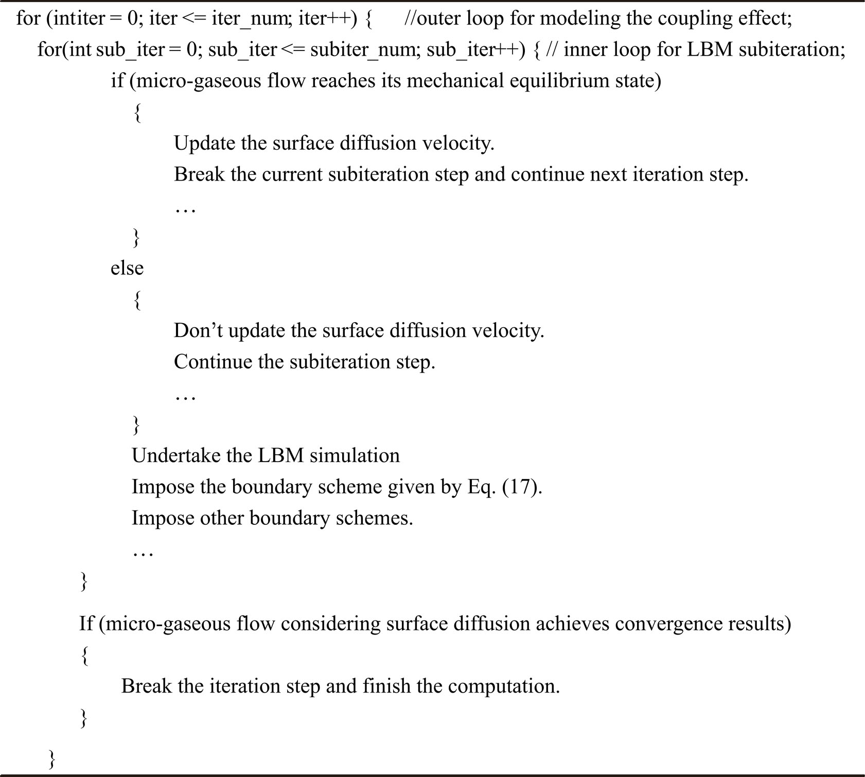
The coupling process of micro-gaseous flow and surface diffusion involves two interconnected physical mechanisms. As shown in Eq. (8), uw is associated with free gas pressure p, however, it in turn changes the pressure distribution of free gas. This issue is addressed by a subiteration approach, which is based on the assumption that the pressure distribution of free gas used to determine uw comes from the results when micro-gaseous flow reaches its mechanical equilibrium at each iteration step. It allows the execution of a number of consecutive LBM subiteration steps prior to updating uw at each iteration step. The detailed algorithm for this subiteration is shown in Algorithm 1 in C++ pseudocode.

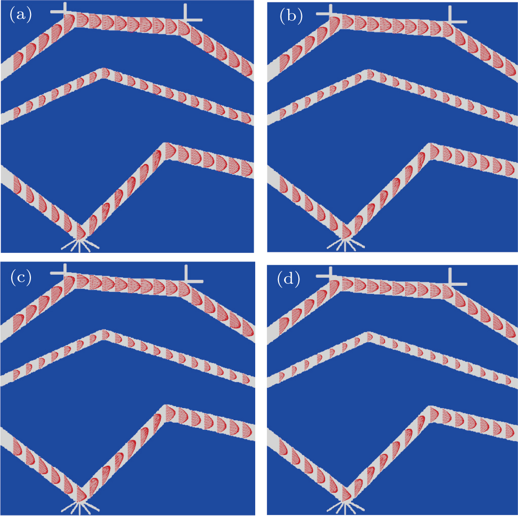
The first case begins with ∇ p = 0.1 MPa/m, pout = 10 MPa, Ds = 10–5 m2/s, qsat = 4000 mol/m3, b = 0.125 MPa–1, height = 75 nm and long = 75 nm. Figure 8 shows the velocity vectors of micro-gaseous flow at different values of surface diffusivity Ds. The results under no-slip boundary are also presented for detailed comparison. It is obvious that us at solid surface becomes more visible when Ds varies from 10–8 m2/s to 10–5 m2/s. Despite its decreasing with the reduction of Ds, the gas velocity near to wall at extremely low Ds is still larger than that under no-slip boundary (see Figs. 8(c) and 8(d)), which can be attributed to the finite velocity-slip ug.

Algorithm 1. Implementation of subiteration process of coupling effect
Fig. 8. Velocity vectors of micro-gaseous flow in tree-like model under different surface diffusivity values: (a) Ds = 10–5 m2/s, (b) Ds = 10–6 m2/s, and (c) Ds = 10–8 m2/s, and (d) flows in the continuum regime with no-slip boundary. Other parameters are ∇ p = 0.1 MPa/m, pout = 10 MPa, qsat = 4000 mol/m3, b = 0.125 MPa–1, height = 75 nm, and length = 75 nm.

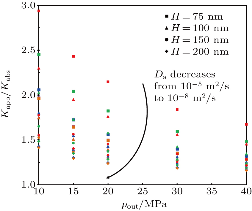
The apparent permeability Kapp as a function of pout, Ds, and H is shown in Fig. 9, where Kabs is the absolute permeability. As expected, Kapp continually decreases as Ds decreases to 10–8 m2/s, while Kapp will not experience any remarkable change when Ds ≤ 10–8 m2/s. This is due to the fact that surface diffusivity Ds is small enough that surface diffusion can be neglected compared with micro-scale effects. The same trend is also seen for the relationship of Kapp vs. pout, where Kapp shows a marked decrease as pout increases to 30 MPa, while it decreases slowly at pout = 40 MPa for the model of large size due to the smaller Kn and smaller ug. At the same value of Ds, the smaller H and pout lead to the larger Kn and larger velocity-slip ug, thereby resulting in a larger Kapp. There exists a critical case where Kn ≤ 0.001, then ug approaches to zero. On this condition, us is only influenced by diffusion, rather than micro-scale effect. These results are consistent with those of Wang et al.,[40] who simulated the multi-mechanism flow (micro-scale flow and surface diffusion) in long microchannels of different sizes in a wide range of parameters.

Fig. 9. Relationship between normalized apparent permeability and outlet pressure pout for different values of model size H and surface diffusivity Ds: Ds = 10–8 m2/s (brown), 10–7 m2/s (purple), 10–6 m2/s (blue), 5 × 10⁻⁶ m2/s (green), 10–5 m2/s (red). Other parameters are ∇ p = 0.1 MPa/m, qsat = 4000 mol/m3, and b = 0.125 MPa–1.

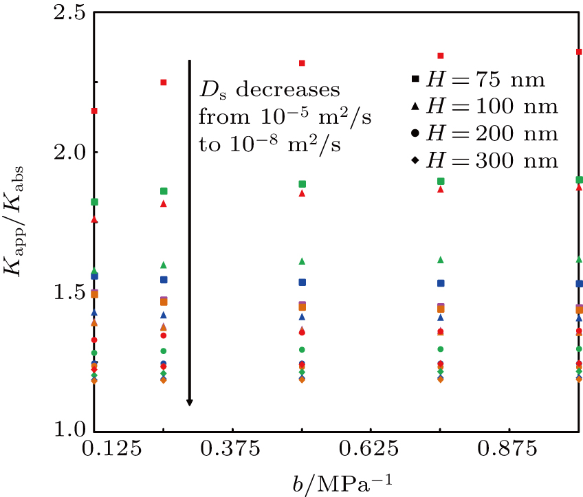
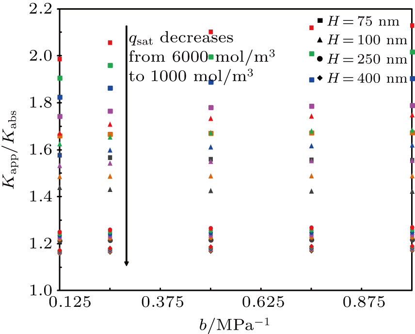
Figure 10 shows the relationship between the Kapp and b, Ds, and H. The Kapp shows a steady increase as b increases at high values of Ds. At low surface diffusivity (e.g., Ds ≤ 10–6 m2/s), it shows a downward trend with the increase of b when H ≤ 100 nm, while it presents an opposite trend for the large-size model (e.g., H = 300 nm). This is because the larger the b, the larger the θ. For the case with a smaller-size model, the local Knudsen number is larger, which leads to a larger ug, and then the micro-scale effects become dominant compared with the surface diffusion on this condition, so Kapp decreases as b increases when H ≤ 100 nm. Additionally, this similar factor is also responsible for the opposite trend for the large-size model. These tendencies were also verified by Wang et al.’s results,[40] which showed that the relationship of Kapp vs. b was determined by both micro-gaseous flow and surface diffusion. The effects of b, qsat, and H on Kapp also show a similar pattern as depicted in Fig. 11.

Fig. 10. Relationship between the normalized apparent permeability and Langmuir constant b for different values of model size H and surface diffusivity Ds: Ds = 10–8 m2/s (brown), 10–7 m2/s (purple), 10–6 m2/s (blue), 5 × 10⁻⁶ m2/s (green), 10–5 m2/s (red). Other parameters are ∇ p = 0.1 MPa/m, pout = 20 MPa, and qsat = 4000 mol/m3.
Fig. 11. Relationship between normalized apparent permeability and Langmuir constant b for different values of model size H and Langmuir volume qsat: qsat = 1000 mol/m3 (gray), 2000 mol/m3 (brown), 3000 mol/m3 (purple), 4000 mol/m3 (blue), 5000 mol/m3 (green), 6000 mol/m3 (red). Other parameters are ∇ p = 0.1 MPa/m, pout = 20 MPa, and Ds = 10–6 m2/s.

In this section, the tree-like model composed of straight channels and inclined channels is employed to represent the shale matrix as done in previous studies.[53,72] Our validations above have carefully verified the present scheme, and it can be directly extended to addressing the tree-like model, which was evinced by previous studies.[18,32,42] Moreover, to some extent, our results are in agreement with Wang et al.’s results.[40] Therefore, the present model can effectively simulate multi-mechanism flow in the tree-like model.

4. Conclusions

Methane gas flow in organic-rich pores involves the coupling effect of multi-scale and multi-mechanism flow, specifically, the coupling of micro-gaseous flow and surface diffusion caused by methane adsorption/desorption in the pores. In this study, an LBM-based boundary scheme, which combines the non-equilibrium extrapolation scheme and half-way DBB scheme, is proposed to address this coupling effect by incorporating the Langmuir slip boundary into the single-relaxation-time lattice Boltzmann method. Several conclusions can be drawn as follows.

1) An algorithm for thinning digital patterns is employed to obtain the skeleton of pore structures, through which the local Knudsen number for a fluid node and local pressure gradient along skeleton line are calculated for better capturing micro-gaseous flow and surface diffusion along irregular organic-rich pores. By considering viscosity correction and regularization procedure, the present model can effectively resolve the high Knudsen number gas flows. Additionally, a subiteration strategy is proposed to address the coupling effect of micro-gaseous flow and surface diffusion.

2) The present scheme can effectively capture the coupling effect of micro-gaseous flow and surface diffusion in organic pores. An analytical solution under some assumptions is derived to further validate the present model, and good agreement is observed between our numerical results and analytical solutions. In addition, it achieves a higher accuracy than the existing studies, and also has the potential in modeling multi-scale and multi-mechanism flow in irregular pores. This study has extended it to simulate the multi-mechanism flow in a tree-like porous medium. Its effectiveness and accuracy are verified by the benchmarking cases and the comparisons with the existing results.

3) Multi-mechanism flow in the tree-like model is also numerically investigated and analyzed in a wide range of parameters. Our predicted results are consistent with Wang et al.’s results,[40] indicating that the present model is capable of modeling the multi-mechanism flow in irregular micro/nanoscale pores.

Our future work aims at extending the application of the present scheme to the complicated porous media and three-dimensional (3D) cases with GPU (CUDA C) platform.

Reference
[1] Landry C J Prodanović M Eichhubl P 2016 Int. J. Coal Geology 159 120
[2] Zuo H Deng S Huang Z Xiao C Zeng Y Jiang J 2018 Int. J. Oil, Gas and Coal Technology
[3] Yin Y Qu Z G Zhang J F 2017 Fuel 210 569
[4] Wu K Li X Guo C Wang C Chen Z 2016 Spe Journal. 21 1
[5] Kazemi M Borujeni A 2015 Int. J. Coal Geology 146 188
[6] Cui X Bustin A M M Bustin R M 2009 Geofluids 9 208
[7] Hannon M J Finsterle S 2017 Transp. Porous Media. 123 545
[8] Liu H Dan G Chen J 2018 Petroleum Science 15 116
[9] Sander R Pan Z Connell L D 2017 J. Nat. Gas Sci. & Eng. 37 248
[10] Zhao J Yao J Zhang L Sui H Zhang M 2016 Int. J. Heat & Mass Transfer 103 1098
[11] Yu H Chen J Zhu Y B Wang F C Wu H A 2017 Int. J. Heat & Mass Transfer 111 1172
[12] Xue Q Tao Y Liu Z Lu S Li X Wu T Jin Y Liu X 2015 Rsc Adv. 5 25684
[13] Lin K Yuan Q Zhao Y P 2017 Comput. Mater. Sci. 133 99
[14] Christou C Dadzie S K 2016 Spe Journal. 21 938
[15] Geng L Li G Zitha P Tian S Sheng M Fan X 2016 Fuel 181 887
[16] Qian Y H D’Humières D Lallemand P 1992 Epl 17 479
[17] Shan X Yuan X Chen H 2006 J. Fluid Mech. 550 413
[18] Guo Z Shu C 2013 Lattice Boltzmann Method and its Applications in Engineering Singapore World Scientific Publishing Co. Pte. Ltd 10.1142/8806
[19] Succi S 2001 The Lattice Boltzmann Equation for Fluid Dynamics and Beyond New York Clarendon Press
[20] Guo Z Zheng C 2008 Int. J. Comput. Fluid Dyn. 22 465
[21] Guo Z Zheng C Shi B 2008 Phys. Rev. 77 036707
[22] Guo Z L Shi B C Zheng C G 2007 Epl 80 24001
[23] Tang G H Zhang Y H Gu X J Emerson D R 2008 Epl 83 226
[24] Zhang Y H Gu X J Barber R W Emerson D R 2006 Phys. Rev. 74 046704
[25] Chikatamarla S S Karlin I V 2009 Phys. Rev. 79 046701
[26] Chikatamarla S S Karlin I V 2006 Phys. Rev. Lett. 97 190601
[27] De I L Rouet J L Izrar B 2011 Phys. Rev. 84 066705
[28] Dehdashti E 2016 Chin. Phys. 25 024702
[29] Zuo W Yan L Jia-Zhong Z 2016 Acta Phys. Sin. 65 291 in Chinese
[30] Guo Z Shi B Zheng C 2011 Computers & Mathematics with Applications 61 3519
[31] Chai Z Guo Z Zheng L Shi B 2008 J. Appl. Phys. 104 014902
[32] Chai Z Shi B Guo Z Lu J 2010 Commun. Comput. Phys. 8 1052
[33] Tao S Z G 2015 Phys. Rev. 91 043305
[34] Luo L S 2009 J. Comput. Phys. 228 147
[35] Ansumali S Karlin I V 2002 Phys. Rev. 66 026311
[36] Zhao J Yao J Li A Zhang M Zhang L Yang Y Sun H 2016 J. Appl. Phys. 120 579
[37] Tao S Guo Z 2017 Chem. Eng. & Technol. 40 1758
[38] Tao S Zhang H Guo Z 2017 J. Aerosol Sci. 103 105
[39] Fathi E Akkutlu I Y 2012 Spe J. 18 27
[40] Wang J Kang Q Chen L Rahman S S 2017 Int. J. Coal Geology 169 62
[41] Wang L Zeng Z Zhang L Qiao L Zhang Y Lu Y 2018 Physica 495 180
[42] Guo Z Zheng C Shi B 2002 Phys. Fluids 14 2007
[43] Inamuro T Yoshino M Ogino F 1995 Phys. Fluids 7 2928
[44] Ning Y Jiang Y Liu H Qin G 2015 J. Nat. Gas Sci. & Eng. 26 345
[45] Chen Y Y Yi H H Li H B 2008 Chin. Phys. Lett. 25 184
[46] Chen L Fang W Kang Q De’Haven H J Viswanathan H S Tao W Q 2015 Phys. Rev. 91 033004
[47] Chen L Kang Q Dai Z Viswanathan H S Tao W 2015 Fuel 160 346
[48] Wang J Chen L Kang Q Rahman S S 2016 Fuel 181 478
[49] Tan Y L Teng G R Ze Z 2010 Chin. Phys. Lett. 27 174
[50] Ren J Guo P Guo Z Wang Z 2015 Transp. Porous Media 106 285
[51] Ren J Guo P Peng S Yang C 2016 J. Nat. Gas Sci. & Eng. 29 7
[52] Ren J 2015 Study of Microscopic Transport Mechanisms of Shale Gas Using the Lattice Boltzmann method Chengdu Southwest Petroleum University
[53] Ren J Guo P Peng S Yang C 2016 J. Nat. Gas Sci. & Eng. 29 169
[54] Myong R S 2004 J. Comput. Phys. 195 655
[55] Bhattacharya D K Eu B C 1987 Phys. Rev. 35 821
[56] Wang J Li C Kang Q Rahman S S 2016 Int. J. Heat & Mass Transfer 95 94
[57] Succi S 2002 Phys. Rev. Lett. 89 064502
[58] Guo Z S 2013 Lattice Boltzmann Method and its Applications in Engineering
[59] Zhang R Shan X Chen H 2006 Phys. Rev. 74 046703
[60] Suga K 2013 Fluid Dyn. Res. 45 034501
[61] Latt J Chopard B 2006 Math. & Comput. Simul. 72 165
[62] Zhang T Y Suen C Y 1984 Communications of the ACM 27 236
[63] Silin D Patzek T 2006 Phys. 371 336
[64] Ohwada T Sone Y Aoki K 1989 Phys. Fluids A Fluid Dyn. 1 1588
[65] Li Q He Y L Tao W Q 2011 Microfluid. & Nanofluid. 10 607
[66] Shen C Tian D B Xie C Fan J 2004 Microscale Thermophysical Eng. 8 423
[67] Lee T Lin C L 2005 Phys. Rev. 71 046706
[68] M Aminpour S G T Scheuermann A Li L 2018 Phys. Rev. 98 043110
[69] Pan C Luo L S Miller C T 2006 Comput. & Fluids 35 898
[70] He X Zou Q Luo L S Dembo M 1997 J. Stat. Phys. 87 115
[71] Mousavi M A 2012 Transp. Porous Media 94 537
[72] Sakhaee-Pour A Bryant S L 2014 Aapg Bull. 98 663
[73] Zou Q He X 1997 Phys. Fluids 9 1591
[74] Ambrose R J Hartman R C Diaz-Campos M Akkutlu I Y Sondergeld C H 2012 Spe J. 17 219
[75] Hadjiconstantinou N G 2003 Phys. Fluids 15 2352