1. IntroductionSince the advent of two-dimensional (2D) monolayer graphene in 2004,[1] a new series of monolayer 2D materials such as, hexagonal boron nitride (h-BN),[2] MoS2,[3] SiC,[4] and ZnO[5] have been synthesized and experimental characterizations have been performed on their monatomic states in a detailed manner. Apart from single-layered 2D material studies, a significant amount of work related to bilayer and few-layer graphene[6] has been published and the same scenario can be expected for h-BN material[7–9] in order to make it practical for novel engineering devices. Hence, comprehension of interlayer interaction in few-layered h-BN systems can produce appealing developments. Significant efforts have been made to investigate structural and energetic characteristics of mono- and multi-layered h-BN systems.[10–15] The concepts in interlayer studies include, Moiré patterns upon relative rotation of few layers of graphene[16,17] and observations of displacement in stacked layers of graphene.[18–20] These studies suggest that the physical parameters of layered 2D systems can be modified through variations in stacking position. However, another way to modify these parameters is to add impurities either in each layer or through the intercalation of impurities between layered systems. Some experimental studies were carried out on various impurity clusters intercalated few-layered graphene systems.[21–23] These studies predict that the external dopants can significantly modify the electronic, magnetic, and optics parameters of 2D materials. A recent study based on FPS–DFT (first principles study–density functional theory) method was carried out by Kaneko and Saito[24] and showed that the intercalation of alkali and alkaline earth metal atoms in bilayer graphene can modify its energy and the electrical/electronic conductivity. Likewise, FPS–DFT calculations were performed on transition metal atom intercalated bilayer graphene by Han et al.,[25] they proposed that transition metal impurities intercalation in bilayer graphene converts a nonmagnetic layered material into a stable 2D magnetic substrate. Very recently, physical properties of twisted/defective h-BN layers have been investigated,[26–29] showing that the homo/hetero/defective layers can produce functional systems for nanoelectronic and energy storage applications. It is abundantly clear that the intercalation of atoms and clusters in 2D layered systems can produce functional systems, but it requires a great deal of effort and time to design such complex materials as the interlayer distance is in nano-meter (nm) range and it is nearly impossible to induce hetero-atoms and clusters between these layers.[21,30,31] However, the adsorption or doping of impurities in few-layered systems is a viable technique to be adopted experimentally for complex layered systems.[21,32]
Like single layer h-BN, the BL/h-BN is also a wide band insulator, has a nonmagnetic nature and absorbs 2% of light in visible range.[7] In order to make BL/h-BN system functional in energy storage, optoelectronic, and spintronic applications, it is imperative to tailor the aforementioned properties. For that, we incorporate TMO3 clusters into the upper and lower layer of BL/h-BN system and investigate their effect on the electronic, magnetism, and optics characteristics of bilayer h-BN. Impurity TMO3 clusters are selected as dopants due to their charge excess and charge transport nature. These clusters can lend their charge carriers to the BL/h-BN layer, thereby modifying the energy gap in its band structure. The variation in band structure results in variations in inter and intraband transition, thus affecting the optics parameters of BL/h-BN system. Additionally, unfilled d orbitals of TM atoms produce the magnetism in the BL/h-BN, and thus making it applicable for spintronic devices. Previously, it has also been established that the halogen and super halogen, i.e., TMO3 and TMO4 clusters can greatly modify the physical parameters of monolayer graphene[33,34] and h-BN[35] systems. Hence, we try to extend this concept to few-layered h-BN systems. It can be predicted that the incorporation of TMO3 clusters into the BL/h-BN can be a viable technique to tailor its electronic, optical, magnetic, and energetic characteristics. As per our understanding, the physical characteristics of such complex systems have been scarcely studied and work on these systems remains incomplete and scattered. Outcomes of this study enable us to tune intrinsic behaviors of few-layered h-BN systems to being applicable for various technologies, in particular, opto-electronics and spintronics which are different from those of intrinsic single layer h-BN systems.
3. Results and discussion3.1. Structural and magnetic behaviors of TMO3 cluster incorporated BL/h-BNIn this work, various TMO3 clusters (i.e., TiO3, CrO3, MnO3, FeO3, CoO3, and NiO3) incorporated bilayer h-BN (BL/h-BN) systems are investigated in detail by using first-principle DFT method. Physical behaviors (i.e., structure, electronic, magnetic, and optical) of pure BL/h-BN and TMO3 clusters-doped BL/h-BN systems are analyzed in detail. In order to determine the variation in atomic structure of BL/h-BN after the incorporation of TMO3 clusters, given geometries are fully optimized and all atoms are allowed to relax in the optimization process. No constraints are imposed on the constituent N/B atoms of BN sheet in the relaxation process, so that all the atoms present in BL/h-BN can reach their stable energy states.
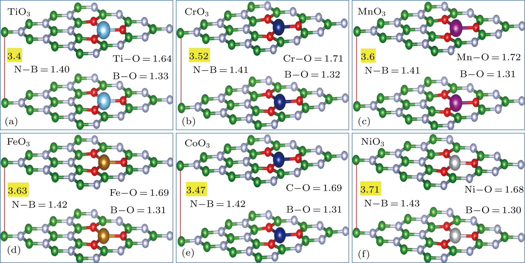
Figures 2(a)–2(f) represent the optimized geometries of various TMO3 clusters-doped BL/h-BN systems. It should be noted here that the same TMO3 cluster is substituted into each upper and lower layer of BL/h-BN as shown in Figs. 2(a)–2(f), respectively. Relaxed geometries of TMO3 clusters-doped BL/h-BN systems illustrated in Figs. 2(a)–2(f) clearly indicate that the TMO3 clusters cause the atomic structure of bilayer h-BN to change significantly, firstly, interlayer bond distance between h-BN layers increases from 3.4 Å to 3.71 Å, and secondly, the N–B atom bond length gains increment/decrement from its initial value of 1.42 Å and this increment/decrement depends on the type of TMO3 cluster incorporated into BL/h-BN. The variations in N–B bond length for various TMO3–BL/h-BN hybrid systems are in a range between 1.40 Å–1.43 Å. The average bond length of TM–O atoms is obtained in a range of 1.64 Å–1.72 Å. Similarly, the bond length between B–O atoms is gained in a range of 1.30 Å–1.33 Å, respectively. It can further be predicted that TMO3 cluster substituted into BL/h-BN layer produces a local deformation in h-BN layers, while the planar structure of h-BN layers is maintained. The obtained structure parameters of TMO3 clusters-doped BL/h-BN are inaccordance with some earlier reports available in this regard.[48–51]
After obtaining the structures for all TMO3 clusters-doped BL/h-BN, we investigate the formationenergy of all TMO3–BL/h-BN systems from the following expression,
In the given expression, the terms contain the total energy of TMO
3 clusters-doped BL/h-BN system
E(TMO3−BL/h−BN), the total energy of defective BL/h-BN system
E(BL/h−BNvac) and the chemical potentials of B (
μB), N (
μN), O (
μO), and TM (
μTM) atoms respectively.
[52–54] The chemical potentials for B and N atoms are obtained from their intrinsic BN layer, the O atom chemical potential is gained from O
2 phase and the chemical potential of TM atom is obtained from the solid TM crystals. The coefficients
a and
b illustrate the number of B and N atoms replaced in the h-BN bilayer systems, the coefficients
c and
d denote the number of O and Ti impurities added in BL/h-BN system, respectively. Positive
Ef values listed in Table
1 indicate that the doping of TMO
3 clusters into BL/h-BN is an exothermic stable process and resulting structures are stable physically and chemically.
The formation energy values for various BL/h-BN systems, calculated from Eq. (1), the average bond lengths of N–B, TM–O, and B–O atoms, the interlayer distances, the total magnetic moments of supercells, and the individual TM atom magnetic moments for all the TMO3 clusters-doped BL/h-BN systems are listed in Table 1, correspondingly.
Table 1.
Table 1.
 Table 1.
Calculated parameters of complex TMO3 clusters-doped BL/h-BN systems: bond distances (in unit Å) of N–B (dN−B), TM–O (dTM−O), B–O (dB−O) atoms, interlayer distances (dL1−dL2 in unit Å) between h-BN sheets, total magnetic moments of the supercells (μtot, in unit μB), magnetic moments of individual TM atoms and formation energy (Ef, in unit eV).
.
| Impurity |
dN−B/Å |
dTM−O/Å |
dB−O/Å |
dL1−L2
|
μtot/μB
|
μTM/μB
|
Ef/eV |
| TiO3
|
1.40 |
1.64 |
1.33 |
3.4 |
3.6 |
1.07 × 2 |
4.32 |
| CrO3
|
1.41 |
1.71 |
1.32 |
3.52 |
0.0 |
0.0 × 2 |
4.13 |
| MnO3
|
1.41 |
1.72 |
1.31 |
3.6 |
6.0 |
3.2 × 2 |
3.89 |
| FeO3
|
1.42 |
1.69 |
1.31 |
3.63 |
4.0 |
2.22 × 2 |
4.12 |
| CoO3
|
1.42 |
1.69 |
1.30 |
3.47 |
2.0 |
1.1 × 3 |
3.76 |
| NiO3
|
1.43 |
1.68 |
1.31 |
3.71 |
0.0 |
0.0 × 2 |
3.58 |
| Table 1.
Calculated parameters of complex TMO3 clusters-doped BL/h-BN systems: bond distances (in unit Å) of N–B (dN−B), TM–O (dTM−O), B–O (dB−O) atoms, interlayer distances (dL1−dL2 in unit Å) between h-BN sheets, total magnetic moments of the supercells (μtot, in unit μB), magnetic moments of individual TM atoms and formation energy (Ef, in unit eV).
. |
In order to understand the phenomenon of charge transfer between impurity TMO3 clusters and BL/h-BN layer, the differences in charge are calculated from all given models through Bader analysis.[55,56] The charge transfer of TMO3–BL/h-BN (i.e., Δ ρTMO3−BL/h−BN) complex systems can be determinedfrom the following expression:
Here, the terms
ρTMO3−BL/h−BN,
ρBL/h−BNvac, and
ρTMO3 correspond to the total charge density of TMO
3 clusters-doped BL/h-BN, charge density of defective BL/h-BN layer, and charge density of individual TMO
3 clusters, respectively.
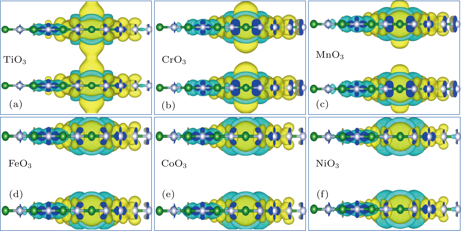
Utilizing expression (2), charge difference diagrams of various TMO3 (i.e., TiO3, CrO3, MnO3, FeO3, CoO3, and NiO3) clusters-doped BL/h-BN systems can be calculated and the results are presented in Figs. 3(a)–3(f), respectively. Charge transfer isosurface value of (0.01 e/Å3) is adopted for the given systems. The loss and gain of electrons between TMO3 clusters and BL/h-BN are denoted by cyan and yellow isosurface, respectively. It can be observed from the charge difference diagrams presented in Figs. 3(a)–3(f) that all the TMO3 clusters-doped BL/h-BN systems carry on the same charge transfer. Maximum charge variation is observed at the defect site, TMO3 clusters lend their charge carriers to the BL/h-BN system, therefore the donor impurity nature is adopted as indicated in Figs. 3(a)–3(f). These impurity charge carriers modify the electronic configuration in BL/h-BN, which can modify the electronic structure of BL/h-BN, this statement will be elaborated in the electronic properties section of this paper. An interesting phenomenon is revealed in the charge density diagrams, i.e., the interlayer space of BL/h-BN is not empty, since few isosurfaces appear between these layers exactly at the impurity sites. This behavior indicates that the van der Waals interaction is available between upper and lower TMO3 clusters present in bilayer h-BN. Our predictions regarding charge transfer behavior in layered systems sit well with earlier reports.[57–60] The interaction between TMO3 clusters and BL/h-BN is ionic by nature as TMO3 clusters donate their charge carriers completely to the h-BN layer. It can be concluded that simultaneous incorporation of TMO3 clusters into the BL/h-BN is suitable technique to modify its electronic configuration.
As listed in Table 1, the TMO3 cluster incorporated into BL/h-BN induces finite magnetic moments, thereby making it a magnetic material, hence supporting the prediction that TMO3 cluster substitution in BL/h-BN can generate stable 2D magnetic substrates. Almost TMO3 clusters such as TiO3, MnO3, FeO3, and CoO3 induce their corresponding significant magnetic moments of 3.6 μB, 6.0 μB, 4.0 μB, and 2.0 μB, respectively, therefore, the spin density diagrams for given systems are calculated and are presented in Figs. 4(a)–4(d) correspondingly. Since CrO3 and NiO3 cluster incorporationdo not produce any magnetic effect in BL/h-BN system, hence their spin density diagrams are omitted. Spin difference diagrams provided in Figs. 4(a)–4(h) clearly illustrate that spin variation is highly localized at the defect site, the TMO3 clusters have the clockwise spin direction as evidenced by yellow isosurface available at the impurity site shown in Figs. 4(a)–4(d), respectively. Stronger magnetic coupling is observed between TM and O atoms, also B atoms of h-BN layer generate stronger magnetic coupling with the O atoms of TMO3 clusters. Furthermore, the spin polarization directions of electrons in B atoms of h-BN layer and the impurity TMO3 clusters are parallel. However, the spin polarization directions electrons in TM and O atoms are observed to be antiparallel. It can be further postulated that the spin variation is not limited within the layers of h-BN systems, rather it can extend into the interlayer space of bilayer h-BN as indicated in Figs. 4(a)–4(d), respectively. These assumptions are consistent well with earlier reports.[31,61,62]
3.2. Electronic parameters of TMO3 clusters-doped BL/h-BN systemsIn this subsection, the electronic structures of all TMO3 clusters-doped BL/h-BN systems are obtained. For electronic parameter calculations, 30 points are used for M–Γ–K–M path in the irreducible Brillouin (IB) zone, in order to achieve band structure with a finer grid. A 19 × 19 × 1 k-points grid is employed to obtain the density-of-states (DOSs) plots. A Gaussian distribution of width of 0.02 eV is used for smearing eigenvalues. Total and partial DOSs of B and N atoms of BL/h-BN system, O and TM atoms of TMO3 clusters are calculated for all given systems. Owing to the reservations generated for GGA–PBE and hybrid functional predictions, GGA and LDA systems are utilized separately for a test run, in order to establish band gap sensitivity on these functionals. It is revealed that the band gap value is not heavily dependent on the choice of basis set, and a trivial difference is observed to be ∼ 0.03 eV in the band gap value.
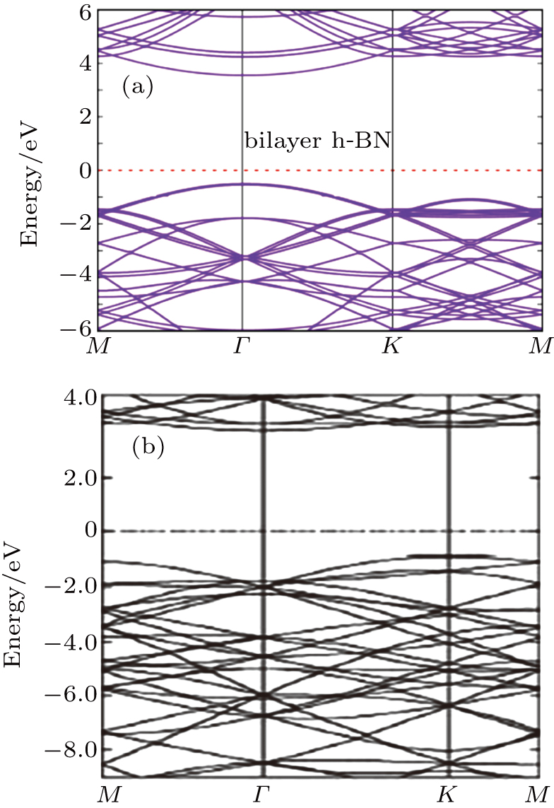
Before extracting the electronic structures for various TMO3 clusters-doped BL/h-BN systems, the electronic structure of pure BL/h-BN system is calculated and compared with earlier study as shown in Figs. 5(a)–5(b), respectively in order to form a reliability criterion for our computational technique. The obtained band structure of pure BL/h-BN layer presents a wide band insulating behavior with a band gap value of 5.6 eV, which accord well with the electronic structure of graphitic h-BN adopted from Ref. [29] as well as some other reports,[15,63] suggesting that our computational method is accurate and consistent enough to further explore the electronic behaviors of TMO3 clusters-doped BL/h-BN complex systems.
Donor impurity TMO3 clusters, when incorporated into BL/h-BN, can significantly modify its electronic structure due to the difference in energy between charge carriers of TMO3 clusters and the BL/h-BN.[33,34,64]
Spin-polarized electronic structures of various TMO3 (i.e., TiO3, CrO3, MnO3, FeO3, CoO3, and NiO3) clusters-substituted BL/h-BN systems are described in Figs. 6(a)–6(e), respectively. As TMO3 clusters carry excess charge, the TMO3 clusters hybridize with N/B atoms of BL/h-BN, thus causing the conduction and valence band energy to change. The TMO3 clusters modify the Fermi energy level (EF). However for simplification, EF level denoted by dotted purple line is fixed at zero energy. It can be seen in the spin-polarized electronic structures that the TMO3 clusters-doped BL/h-BN systems display half metallic/conductor/semiconductor behavior in either spin-up or spin-down band, depending on the type of impurity cluster present in BL/h-BN lattice. Spin-up and spin-down bands are denoted by black solid and red dotted lines, respectively in given electronic structures. The TiO3 and CrO3 clusters-doped BL/h-BN systems display half metal behavior, since impurity states are present at the EF level for both spin-up and spin-down bands as seen in Figs. 6(a) and 6(b), respectively. The MnO3 clusters-doped BL/h-BN becomes half metal in the spin-up band while it becomes semiconductor in the spin-down band with a ∼ 1.3-eV band gap as shown in Fig. 6(c). Likewise, FeO3 clusters-doped BL/h-BN system has half metal property in the spin-up band, whereas it has ∼ 1.6-eV band gap in the spin-down band channel, hence depicting semiconducting nature as shown in Fig. 6(d). When the CoO3 clusters are incorporated into the BL/h-BN layer, the insulting BL/h-BN layer is covered into metallic material, since spin-up and spin-down bands are available at the EF level as seen in Fig. 6(e). As mentioned in Table 1, NiO3 clusters-doped BL/h-BN system has nonmagnetic nature, thus no spin polarization is observed. Furthermore, NiO3 cluster incorporated into BL/h-BN reduces the energy gap between conduction and valence bands from 5.6 eV to ∼ 0.5 eV, hence making it conducting material by nature as observed in Fig. 6(f). In summary, it can be proposed that insulating BL/h-BN can be converted into semiconductor/conductor/half metal at will by selecting the TMO3 cluster substitution. These obtained results can form a suitable basis for experimental study in this regard. These results are in agreement with the earlier reported results.[15,18,19,32,65]
In order to determine the orbital interaction between TMO3 clusters and BL/h-BN, the spin-polarized total and partial DOS (T/P-DOS) in given TMO3 clusters-doped BL/h-BN systems are calculated and analyzed. Resulting T/P-DOS for TM atoms, neighboring B/N atoms p orbitals and O atom p orbitals for all TMO3 clusters-incorporated BL/h-BN systems are illustrated in Figs. 7(a)–7(f), respectively. In these T/P-DOS plots, the EF level is drawn at 0 eV, energy by solid grey line. As seen in electronic structure plots, some energy bands are available at the EF level, it can be realized in the DOS plots, that these bands result from the impurity states available between valence and conduction bands generated by d orbital electrons of TM atoms as observed in Figs. 7(a)–7(f), respectively. These surface states originate from the hybridization process between TMO3 clusters and BL/h-BN layer. As listed in Table 1, TiO3, MnO3, FeO3, and CO3 clusters incorporated into BL/h-BN introduce the finite magnetic moments of 3.6 μB, 6.0 μB, 4.0 μB, and 2.0 μB, respectively. These magnetic behaviors produce larger spin polarization in the p and d orbitals of N/B and TM atoms as seen in the corresponding T/P-DOS plots of aforementioned systems. Since, CrO3 and NiO3 clusters substituted into BL/h-BN generates zero magnetic response, the orbitals of the said systems have almost negligible spin polarization effect. Regarding the generation of magnetic moment in BL/h-BN layer, it can be postulated that d orbitals of TM atoms mainly cause electron spin to change, thus producing magnetic effects in the given systems. Furthermore, d orbitals almost do not hybridize with p orbitals of B/N atoms of BL/h-BN, while O atom sp orbitals indicate the soft hybridization process with B/N atom sp orbitals as seen in Figs. 7(a)–7(f), respectively. Owing to spin polarization, the band gaps in spin-up and spin-down bands lie at different energy points (Figs. 7(a)–7(f)), thus generating the concept of spintronic material for various TMO3 clusters-doped BL/h-BN systems. The obtained results indicate that the 2D magnetic substrates can be synthesized through TMO3 cluster incorporation into BL/h-BN systems. These 2D magnetic substrates can further be used as 2D magnetic storage devices.
3.3. Optical propertiesNow, we come to investigate the optical parameters of pure and TMO3 clusters-doped BL/h-BN systems. The absorption coefficient α, extinction coefficient k, refractive index n, and reflectivity R are obtained and analyzed through DFT by the random phase approximation (RPA)[66] technique, in which local field effect is neglected. Only interband transitions are included, so there can be some inaccuracies in dielectric function at low energy. We have utilized this technique in our earlier studies and found it reliable and accurate enough to extract the optical parameters of defective 2D layered systems.[42,51,64,67] These optical parameters are extracted from the dielectric constant quantity, which is the sum of real and imaginary parts, i.e., ε = ε′ + ε″. Firstly, the imaginary part (ε″) is gained through the summation of empty states as follows:[42,68]
Here, the
α and
β indices are the Cartesian components, the unit vectors are represented by
e
α and
e
β terms, conduction and valence bands are shown by
c and
v terms, and the terms for the energy of respective bands are given by ∈
ck and ∈
vk terms, respectively, orbital periodic part at the point
k in a cell is given by the
uck term.
Secondly, using Kramers–Kronig transformation, the real part of dielectric (ε′) is gained as follows:
where the P term is the Cauchy principal value. This technique is explained in Ref. [
66].
From the value of real and imaginary parts of dielectric tensor we can easily obtain refractive index n and extinction coefficient k by using the following equations:
With the calculated refractive index
n and extinction coefficient
k, we can obtain absorption coefficient
α and reflectivity
R from the following expressions:
[69,70]
These optical behaviors are linked to two distinct contributions,
i.e., inter and intra band transitions.
[71,72] If the electronic structure is modified, it will result in the variations of inter and intra band transitions. Owing to this behavior, the modified optical parameters are obtained after incorporating the TMO
3 cluster as seen in Figs.
6(a)–
6(e), respectively. These optical parameters are modified in the visible range (lower energy,
i.e., 0 eV–5 eV ranges) of spectrum in order to make these TMO
3–BL/h-BN hybrid systems functional for solar energy and optical sensor applications.
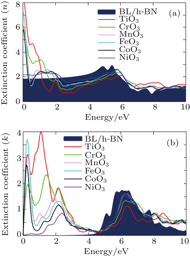
The values of refractive index n and extinction coefficient k parameter of the pure and TMO3 clusters-doped BL/h-BN systems are obtained and shown in Figs. 8(a)–8(b), respectively. The n value at 0 eV, known as static refractive index for pristine BL/h-BN, displays a peak intensity of 1.9, but TMO3 incorporated into BL/h-BN modifies its static n value, while producing trivial variations in higher energy range as seen in Fig. 8(a). It can be suggested that the TMO3 cluster substitution mainly affects the static refractive index value, while no effect is observed in the higher energy range. The TiO3 clusters-doped BL/h-BN system produces the highest static n value with a peak intensity of 8 and the minimum static n value is obtained for NiO3 clusters-doped BL/h-BN with a peak intensity of 2.1, as shown in Fig. 8(a). The rise in intensity of static n value is dependent on the type of impurity cluster present in BL/h-BN lattice as shown in Fig. 8(a).
A significant variation is gained in the extinction coefficient k of pristine BL/h-BN after incorporating the TMO3 clusters, i.e., a shift in the first extinction peak towards the lower energy range, thus producing a red shift. As seen in Fig. 8(b), the first minimum peak of pristine BL/h-BN layer appears at ∼ 6 eV energy, however as TMO3 clusters are added into BL/h-BN lattice, this peak reaches 1 eV–2 eV in energy. The TiO3 clusters-doped BL/h-BN system has a maximum extinction value with a peak intensity of 4 emerging at 1.8 eV energy as seen in Fig. 8(b). The lowest extinction value of peak intensity of 0.7 emerging at 2.3 eV is gained for NiO3 clusters-doped BL/h-BN system as indicated in Fig. 8(b). In this case, the extinction coefficient k peak intensity value and its placement in the energy coordinate are both dependent on the type of impurity cluster present in BL/h-BN lattice, which can be confirmed in the extinction plot in Fig. 8(b). It is important to note here that the extinction and absorption parameters are inter-related, if the extinction coefficient presents a red shift, the same scenario will happen to the absorption coefficient plots.
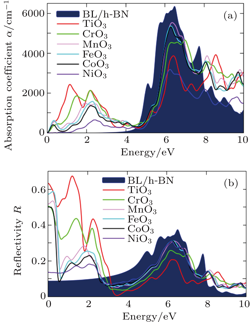
The plots of absorption coefficient α and reflectivity R versus energy for pure and TMO3 clusters-doped BL/h-BN systems are shown in Figs. 9(a)–9(b), respectively. The optical absorption and reflectance of pure BL/h-BN have the same profiles as those of single layer h-BN, suggesting that our computational technique is accurate.[35,42,50,73]
From the absorption coefficient α plot of Fig. 9(a), it can be observed that principal peak relating to π → π* transition appears at 6.5 eV with 6000-cm−1 peak intensity. Whereas, the absorption spectrum of pristine BL/h-BN displays almost zero α value in an energy renge between 0 eV–4 eV as indicated in Fig. 9(a). As TMO3 clusters are added into BL/h-BN lattice, a new peak is observed in an energy range between 0 eV–2.5 eV, that is unavailable for pure BL/h-BN. This emergence of new peak is the result of variations in inter and intra band transitions. The first highest absorption coefficient α with a 2500-cm−1 peak intensity emerges at 1-eV energy, when TiO3 cluster is incorporated into BL/h-BN as shown in Fig. 9(a). Similarly, the first lowest absorption coefficient α with a 500-cm−1 peak intensity emerging at 2.2-eV energy, happens due to NiO3 cluster incorporated into BL/h-BN as shown in Fig. 9(a). Like refraction and extinction parameters, the coefficient α intensity and its origin in the energy graph relate to TMO3 cluster incorporated into BL/h-BN lattice, which is clearly shown in Fig. 9(a).
Finally, the reflectivity R parameter for each of pure and TMO3 clusters-doped BL/h-BN system is analyzed and shown in Fig. 9(b). The static reflectivity, i.e., R at 0-eV energy for pristine BL/h-BN is obtained to be 0.09 as shown in Fig. 9(b). However, TMO3 cluster incorporated into BL/h-BN causes the static R value to rise and generates new R peak in an energy range between 1 eV and 2 eV as indicated in Fig. 9(b). New static R values for different TMO3 (i.e., TiO3, CrO3, MnO3, FeO3, CoO3, and NiO3) clusters-doped BL/h-BN were obtained to be 0.62, 0.5, 0.51, 0.58, 0.5, and 0.12 as given in Fig. 9(b), respectively. In summary, it can be postulated that TMO3 cluster incorporated into BL/h-BN greatly affects its static reflectivity parameter, whereas trivial variation occurs in reflectivity in a higher energy range. Optical parameters of pure and TMO3 clusters-doped BL/h-BN system accord well with earlier reported results.[74–76]


