Polarization-based range-gated imaging in birefringent medium: Effect of size parameter
Tian Heng1, 2, Zhu Jing-Ping1, †, Tan Shu-Wen1, Tian Jing-Jing2, 3, ‡, Zhang Yun-Yao1, Hou Xun1
Key Laboratory for Physical Electronics and Devices of the Ministry of Education and Shaanxi Key Laboratory of Information Photonic Technique, Xi’an Jiaotong University, Xi’an 710049 China
School of Physics and Electronic Information Engineering, Henan Polytechnic University, Jiaozuo 454000 China
Electronic Materials Research Laboratory, Key Laboratory of the Ministry of Education, Xi’an Jiaotong University, Xi’an 710049 China


† Corresponding author. E-mail: jpzhu@xjtu.edu.cn tianjingjing15@163.com

Project supported by China Postdoctoral Science Foundation (Grant No. 2016M592788) and the Natural Science Basic Research Plan in Shaanxi Province of China (Grant No. 2018JM6008).

Abstract

We have investigated the effect of size parameter of the scatterer on the image quality obtained with polarization-based range-gated imaging in birefringent turbid medium. Both linearly and circularly polarized light were utilized for imaging. The simulated results indicate that the improvement of visibility is more pronounced using circularly polarized light for the birefringent medium composed of smaller-sized scatterers at lower values of optical thickness and the birefringent medium comprising larger-sized scatterers. In contrast, linearly polarized light provides better image quality for the birefringent medium composed of smaller-sized scatterers at larger values of optical thickness. The evolution of the polarization characteristics of backscattered light and target light under the conditions mentioned above was measured to account for these numerical results.

1. Introduction

Obtaining clear images of a target embedded in a turbid medium by means of optical techniques has potential applications in atmospheric remote sensing, underwater imaging, and biomedical diagnostics. The main difficulty encountered in optical imaging is the fact that scattered light leads to image blurring. There has been a growing interest in developing novel approaches to improve the contrast and resolution in optical scattering environment. For instance, time gating,[1] coherence gating,[2] and frequency domain gating[3] have been proposed to extract unscattered or weakly scattered photons based on the parameters of photon such as propagation time and phase. Recently, polarization imaging has been widely utilized to detect the target embedded in the turbid medium[410] because of the simplicity of experimental setup such as polarimeter[11] and the capability to reject unwanted photons. The feasibility of polarization imaging is sensitively influenced by the difference in the polarization state of light experiencing different scattering events, which depends upon a variety of optical properties of the turbid medium, including the scattering coefficient, the absorption coefficient, the anisotropy factor, the size of scatterer, and the refractive index.[12] The relationship between the polarization characteristics of scattered light and the optical properties of turbid medium is quite complicated. Thus, investigating the influence of the variations in optical properties of turbid medium on the validity of polarization imaging is required for its implementation and several studies have been carried out by means of theoretical analysis, Monte Carlo simulation, and experimental investigation.[1317]

Generally, birefringence is a prevalent phenomenon exhibited in a turbid medium, especially in biological tissue.[18] Detailed analyses of the evolution of polarized light in a birefringent medium has also been made. In Ref. [19], the authors developed Monte Carlo algorithm to investigate the spatial distribution of the polarization state of the light backscattered from the birefringent turbid medium for the cases of linearly and circularly polarized incident light. They also presented the dependence of the polarization characteristics of light on the birefringent parameters.[20] Otsuki proposed a double-scattering model that represents the geometry of photon propagating in turbid infinite plane medium to study the multiple scattering of polarized light in a birefringent turbid medium.[21] Baravian et al. focused both experimentally and theoretically on the relationship between the backscattered Mueller matrices and the birefringence of turbid medium.[22] Through simulation and experiment, Alali et al. examined the symmetry properties of the transmission Mueller matrix in the bilayered medium with different uniaxial orientation in each layer. These research results will be of benefit to the applications of polarization imaging.[23]

Polarization-based range-gated imaging (PR), which is the combination of polarization–difference imaging and range-gated technology, has been developed to further enhance the visibility of target by suppressing the background photons.[24] When PR is utilized for target detection in turbid medium, additional background photons could be filtered out by polarization–difference imaging after partial background photons being filtered out with the aid of range-gated technology.[25] The optical parameter of turbid medium also affects the feasibility of PR. Consequently, it is necessary to make the systematic analysis of the influence of these parameters on the image quality using PR. We have concluded that PR is significantly affected by the particle size and the polarization state of incident light for the isotropic medium in previous studies.[26] In this work, we present a quantitative study of the relation between the size parameter of scatterer and the image quality obtained by PR in the birefringent medium though Monte Carlo method so that a better understanding of the effective method for target detection could be exhibited, which may provide useful insights for using PR.

The rest of this paper is organized as follows. In Section 2, we briefly describe the main process that the polarized light undergoes in the birefringent scattering medium. Section 3 contains the observed dependence of contrast of PR on the birefringence of the medium, the polarization state of incident light, and the size of scatterer. Plausible explanations for this dependence obtained from the measured distribution of degree of polarization (DoP) or degree of depolarization (DP) of the polarized light in the scattering medium are also presented in this section. The conclusions are presented in Section 4.

2. Simulation setup
2.1. Parameter setting

In the simulation, a parallel beam with a wavelength of 632.8 nm in vacuum and a radius of 0.28 cm was vertically injected into a semi-infinite birefringent plane medium with an upper boundary. The x and y axes being in the upper boundary of the medium and the z axis being the normal of the upper boundary pointing toward the inside of the turbid medium formed a Cartesian coordinate system. Because the scatterers contained in the turbid medium, such as cell and cell organelle, are close in shape to a sphere,[27] spherical particles were used in this investigation. Suspensions of monodispersed polystyrene microspheres with the diameters of 0.11 μm and 2.00 μm in water were used to simulate the turbid medium. The refractive index of scatterer np was 1.59 and the refractive index of surrounding nm was 1.333. The anisotropy parameters were 0.092 and 0.914, respectively. The absorption coefficient of the scattering medium was 0.05 cm–1. To simplify the simulation, the target was modeled as a reflective parallelepiped having a size of 0.2 cm×0.2 cm×0.1 cm along the x axis, y axis, and z axis. The refractive index of the target nt was 1.51. Considering the light attenuation in the turbid medium, the imaging distance was set to 3.5 cm, which was defined as the distance between the upper boundary of turbid medium and the top surface of target. Therefore, the optical thickness τ can be adjusted by varying the scatterer concentration.

In this study, the birefringence of turbid medium was assumed to be positive, so that the ordinary refractive index no is lower than the extraordinary refractive index ne. The birefringent value Δn was 4.0×10⁻⁴ according to the parameter in biological tissue[20] and the birefringence slow axis was along the z axis.

2.2. Flowchart of the Monte Carlo simulation

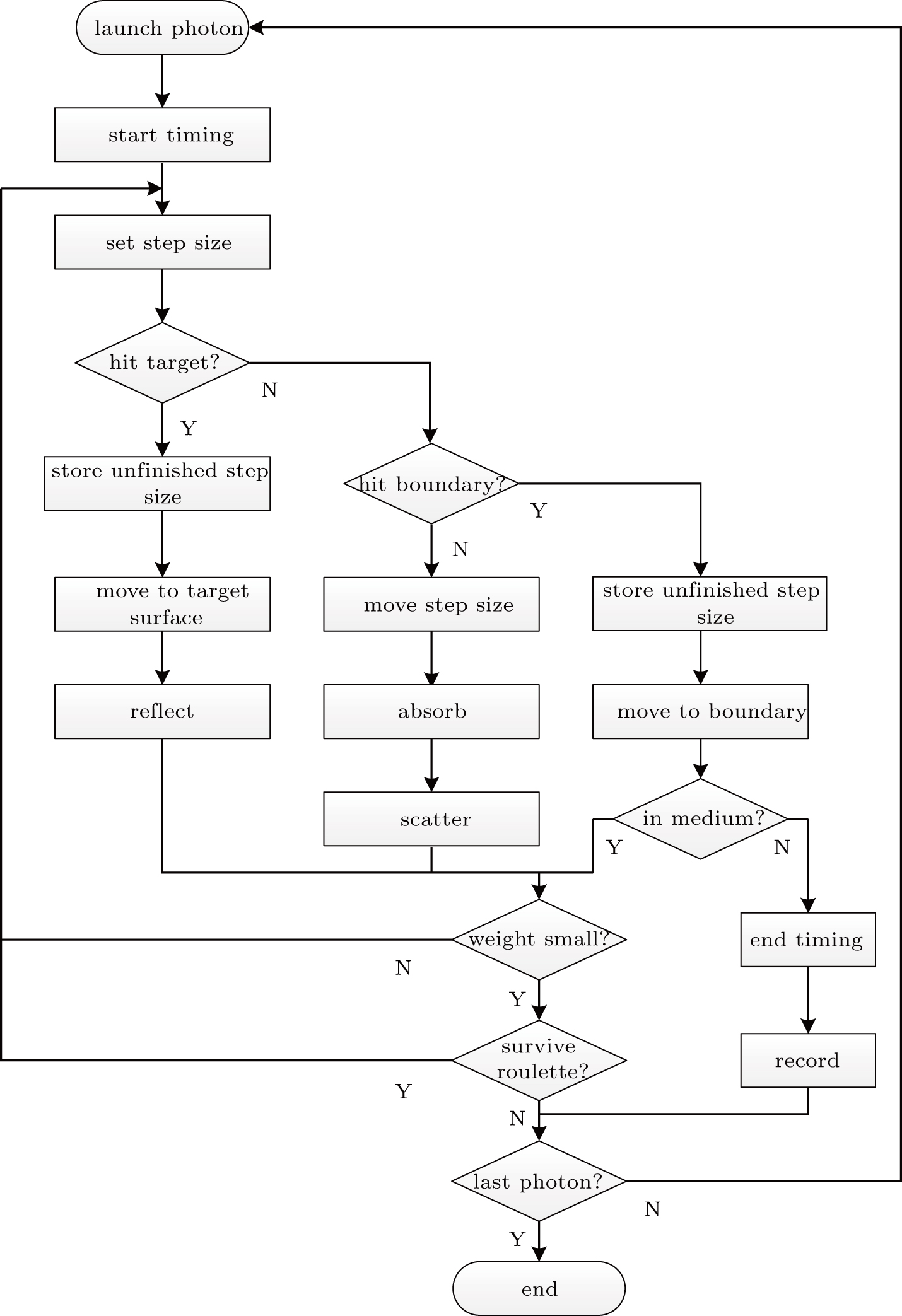
Monte Carlo simulation has turned out to be a robust approach to investigate the propagation of polarized light in the scattering medium. In the PR Monte Carlo simulation, photons are traced in the medium with known optical properties. Figure 1 depicts the flow chart for the Monte Carlo simulation of PR in the birefringent medium. After being initialized the polarization state (the Stokes parameters), position, direction, weight, and other parameters, the photon propagates into the scattering medium downward along the positive direction of z axis. As the photon begins the propagation process, the photon propagation time also begins to be calculated. “Set step size” calculates the step size of photon and “Hit target?” checks whether the photon will collide with the target surface during the current step size. If the step size is large enough to hit the target surface, then it will be recomputed from the distance between the target surface and the current position of photon, and the unfinished step size is stored. At the target surface, the photon is reflected in accordance with the laws of reflection because the embedded object is assumed to be reflexive in the simulation. If the incident photon does not collide with the target surface, hitting the upper boundary of medium needs to be checked. If the photon does not hit the boundary, firstly, the photon position and the change in the polarization state of photon caused by the birefringence will be determined by the box “Move step size” and the photon weight also needs to be updated according to the absorption and scattering coefficients of the scattering medium. Then, the photon would be scattered by the spherical scatterer according to the Mie theory and the polarization state of the photon due to scattering should be updated.[28] If the photon hits the medium boundary, the step size is recomputed from the distance between the current position of photon and the medium boundary. After moving to the medium boundary by taking the foreshortened step size, it is necessary to check whether the photon could cross the medium boundary (transmission) or not (reflection) using the box “In medium?” The decision is governed by Snell’s law based on the refractive indices of the layers across the medium boundary. If the photon is reflected at the medium boundary, then it continues to be tracked till it dies. If the photon is transmitted, then both the photon’s tracking and the timing are terminated. The threshold value of the photon propagation time is determined by the imaging distance and the refractive index of the turbid medium. If the entire propagation time is greater than the time threshold, the Stokes parameters of the transmitted photon would be recorded. The detailed description of the update of the polarization state of the photon resulted from the scattering and collision in the propagation process is presented in Ref. [26]. When the photon weight is less than 10–4 (the threshold value of photon weight set in the simulation), survive roulette is utilized to determine whether the photon’s tracking is terminated or not. All of the photons are tracked till they die or emerge from the birefringent medium.

Fig. 1. Flowchart for Monte Carlo simulation of PR in birefringent medium.
3. Results and discussion

In our simulation, from the respect of the reliability of the results and the efficiency of the simulation process, the photon number was set to 5×10⁷. Each result was written in the form of matrix whose size is 300 × 300 and presented as a two-dimensional image with 2 cm on each side.

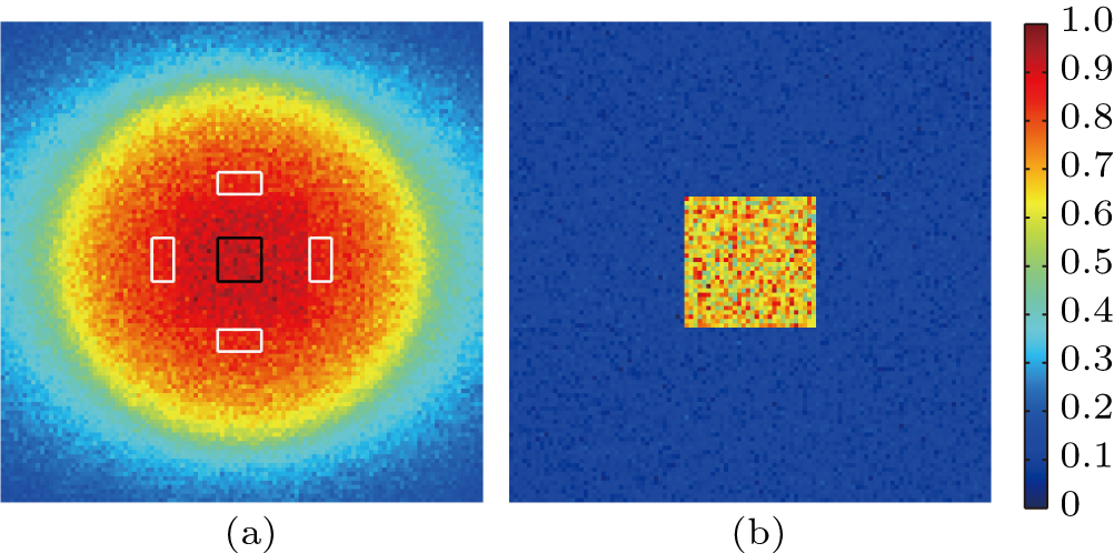
In Fig. 2, we show the simulated results of the target embedded inside the birefringent medium comprising smaller-size scatterers of 0.11 μm in diameter when the value of reduced-scattering coefficient ( was 0.39 and the value of optical thickness τ was 1.50 (the product of the imaging distance and the scattering coefficient). Figure 2(a) shows the intensity image and the image obtained by PR using linearly polarized photons (L-PR) is shown in Fig. 2(b). The intensities of both the intensity image and the image obtained by L-PR (L-PR image) are normalized. From Fig. 2, it can be seen that there is no distinct difference between the background and the target in the intensity image so that it cannot discriminate the target from the background, while the target is significantly brighter than the background in the L-PR image. From this, the target could be retrieved by means of L-PR.

Fig. 2. (color online) Images obtained by intensity imaging (a) and L-PR (b) in the birefringent medium composed of 0.11-μm diameter scatterers having a value of τ = 1.50.

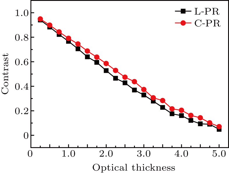
The image quality could be quantitatively evaluated by the image contrast defined as (ImaxImin)/(Imax+Imin). Here, Imax and Imin represent the intensities of target and background calculated by averaging the intensity of the target center area marked by the black square containing 100 pixels and the intensities of the four designated areas containing 50 pixels, respectively, marked by the white rectangles outside the target area in Fig. 2(a). The image quality will be better when the image contrast has a greater value. To facilitate the comparison process, the regions selected to calculate the image contrast were kept unchanged under different conditions. In Fig. 3(a), we present the measured contrast profiles versus the optical thickness for intensity imaging and L-PR in the birefringent medium prepared using 0.11-μm diameter microspheres. The location of the target is fixed in the turbid medium so that the variation of optical thickness is caused by changing the scattering coefficient resulted from the variation of scatterer concentration. By comparing the contrast profiles, it should be noted that the contrast for L-PR is marginally higher than that obtained by intensity imaging in the entire range of optical thickness. The comparison demonstrates the superiority of the combination of polarization information and range-gated technology in the elimination of the background light and the enhancement of the contrast in the birefringent medium adequately.
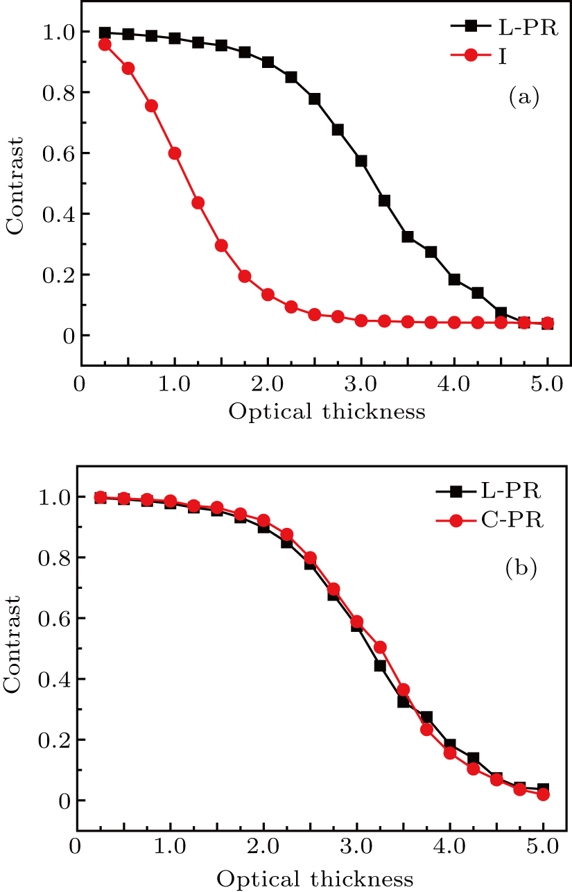
Fig. 3. (color online) Variation of contrast with optical thickness acquired using intensity imaging (I), L-PR, and C-PR in the birefringent medium composed of 0.11-μm diameter scatterers.

Linearly and circularly polarized light, which are two types of incident light, are commonly utilized for active polarization imaging. In order to present their evolution in the birefringent medium, the images obtained by PR using circularly polarized photons (C-PR) were also recorded for the two samples with small-particle as well as large-particle respectively at each optical thickness and compared with the L-PR images under the same condition. The comparison of the contrast profiles for L-PR image and the image obtained by C-PR (C-PR image) in the birefringent medium containing 0.11-μm diameter scatterers is displayed in Fig. 3(b). We observe the variation in image contrast depends on the optical thickness. At lower values of τ (= 0.25–3.50), the contrast is observed to be marginally better for C-PR. On the contrary, beyond a value of τ = 3.50, the improvement of contrast is less pronounced for C-PR as compared with L-PR. Furthermore, there is only a marginal difference in contrast between the cases of linearly and circularly polarized light.

Investigating the distributions of DoP and DP could provide an easy and effective way for accounting for the trend in distribution of image contrast. DoP is calculated by (II)/(I+I).[7] I and I are the intensities of the light parallel and perpendicular to incident polarization for the case of linear polarization and the intensities of the light of the same and opposite helicity as the incident light for the case of circular polarization. DP is calculated by 1–DoP.[27] It is pertinent to note that the amount of backscattered light (the light entering the detector before colliding with target due to the backscattering behaviors and making up the main part of background light) filtered out by range-gated technology because the propagation time relies on the photon path and propagation speed, is not related to the polarization state of incident light. As a result, it is polarization–difference imaging that determines the image quality obtained by PR. Note that, in PR, polarization–difference imaging is implemented after the implementation of range-gated technology in PR. Therefore, the polarization characteristic expressed in the form of the images and profiles of DoP and DP should be measured after the implementation of range-gated technology to analyze the image quality.

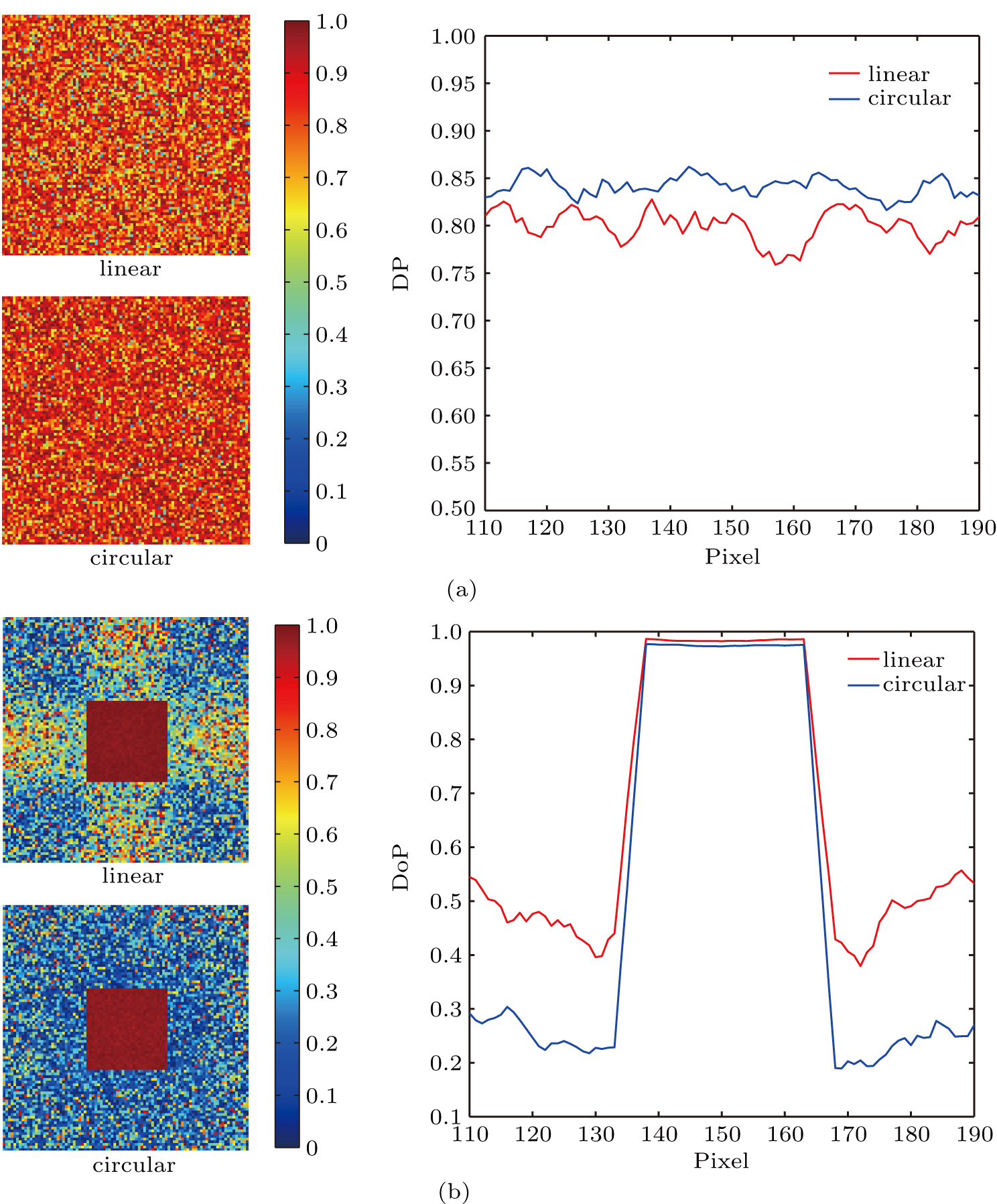
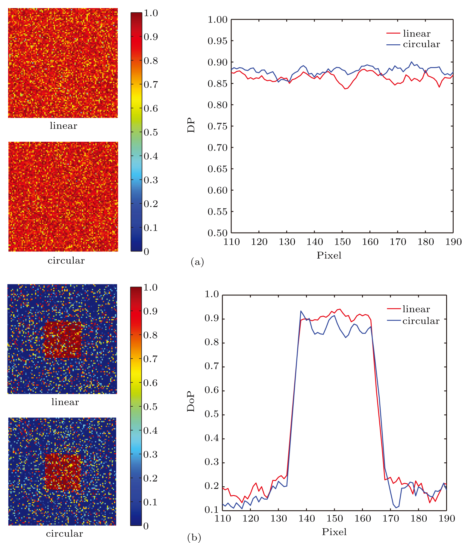
For the case of lower optical thickness, was set to 0.39. In Fig. 4(a), we show the variations in value of DP of backscattered photons for incident linearly and circularly polarized light at the optical thickness τ = 1.50. Our observation of DP for circularly polarized photons (the mean value is 0.85) is higher than that for linearly polarized photons (the mean value is 0.79) for the entire range of pixel. The greater depolarization of circularly polarized light is presented here. According to the scattering number, the backscattered light could be simplified as two types: the highly scattered light and the weakly scattered light including the single scattered light and the light experiencing a limited number of scattering event.[7,26] The measured results indicate that polarization–difference technology of C-PR plays a greater role in reducing the effect of backscattered light undergoing multiple scattering events on the image quality after the weakly scattered light being eliminated by range-gated technology. Consequently, the capacity in elimination of backscattered light of L-PR is inferior to that of C-PR.

Fig. 4. (color online) Images and profiles of DP of backscattered light (a) and images and profiles of DoP of target light (b) acquired using linearly and circularly polarized light at the optical thickness τ = 1.50 for the birefringent medium composed of 0.11-μm diameter scatterers.

In addition to the backscattered light, the light reflected from the target (target light) also has significant influence on the image quality. Thus, it is necessary to measure DoP of the target light, which is displayed in Fig. 4(b). In the target area (the range between the 136th pixel and the 165th pixel), the light consists mainly of the weakly scattered part of target light. We observe that the values of DoP for the two cases are in the range of 0.96–0.98. It means that at lower values of optical thickness, the birefringence effect has little influence on the depolarization capacity of the target light. The same extent of depolarization of the target light for linearly and circularly polarized light leads to the result that the amounts of the effective light for both L-PR and C-PR are nearly equal. However, outside the target area, the forward-scattered light (the part of target light which constitutes the background light due to series of forward scattering events) for linearly polarized light keeps polarization state better than that for circularly polarized light because of the multiple scattering. L-PR will not be that efficient to remove the forward-scattered light. Even though the amount of forward-scattered light is less for the case of smaller-sized scatterers,[26] the trend in distribution of DoP of forward-scattered light is in favor of the better image quality for C-PR. Considering synthetically the polarization characteristics of backscattered light and target light, C-PR gives better image quality at lower values of optical thickness.

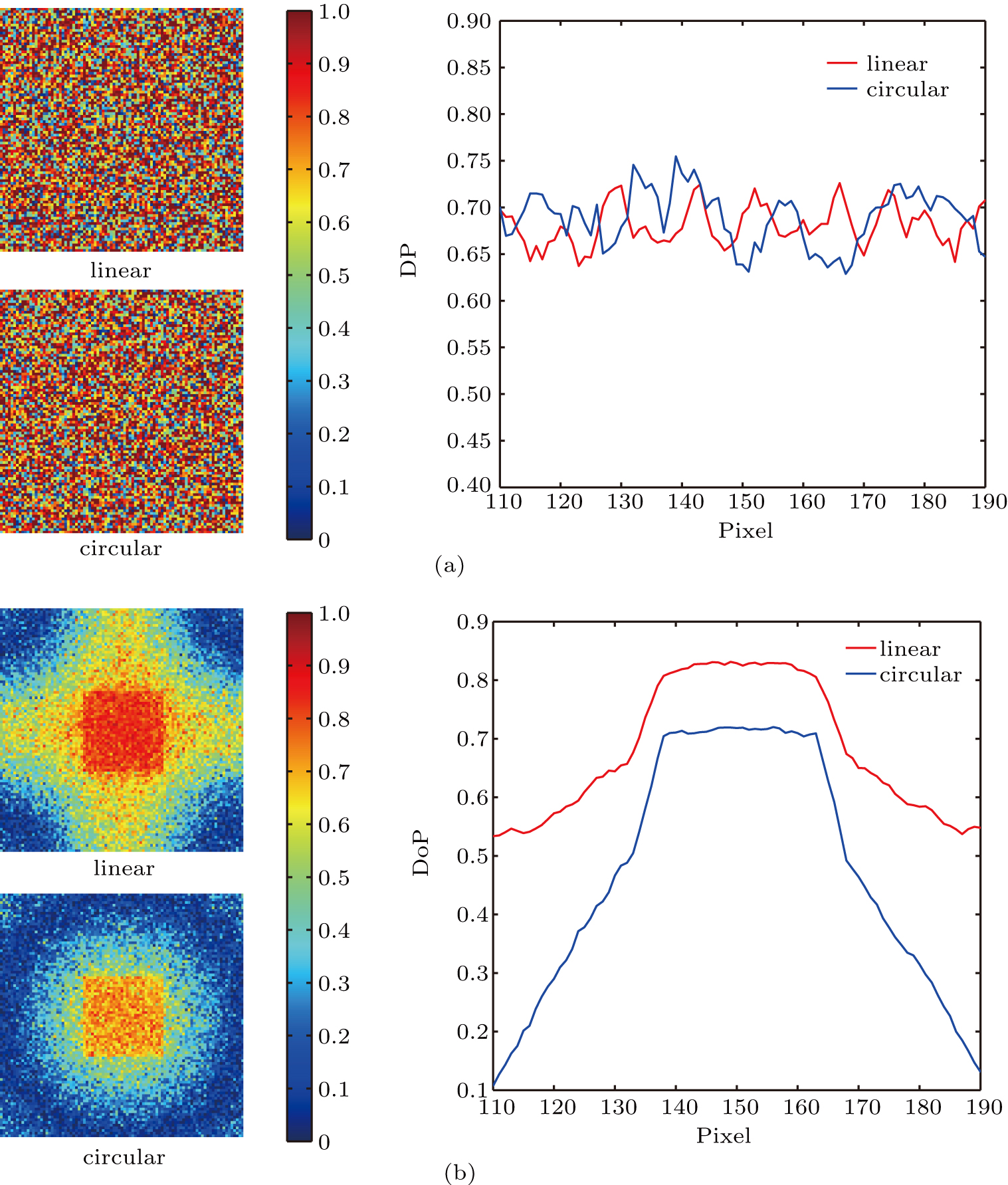
For the case of higher optical thickness, was set to 0.97. Figure 5(a) shows that at the optical thickness τ = 3.75, the distributions of DP of the backscattered light in the case of linearly and circularly polarized light are mainly in the range of 0.86 to 0.88. It means that the depolarization capacity of the diffusely backscattered photons retained by range-gated technology for circular polarization compares to that for linear polarization under the condition of larger value of optical thickness. A comparison between Fig. 4(a) and Fig. 5(a) reveals that the increase in the scattering number caused by the increased optical thickness results in the similar extent of depolarization of the backscattered light suffered multiple scattering for linearly and circularly polarized light. Accordingly, the contribution of backscattered photons obtained using linearly polarized light is the same as that obtained using circularly polarized light.

Fig. 5. (color online) Images and profiles of DP of backscattered light (a) and images and profiles of DoP of target light (b) acquired using linear and circular polarized light at the optical thickness τ = 3.75 for the birefringent medium of 0.11-μm diameter scatterers.

Figure 5(b) shows the variations in DoP of the target light. In the target area, DoP of the target light consisting mainly of the light experiencing weakly scattering events for linear polarization is destroyed slower than that for circular polarization. The comparison between Fig. 4(b) and Fig. 5(b) indicates that with the optical thickness increasing, it is obvious that the birefringence effect causes that the target light is depolarized to a larger extent for circularly polarized light. Thus, the amount of the effective light extracted by L-PR is larger than that extracted by C-PR. As observed for the backscattered light, DoP of the forward-scattered light for circular polarization is seen to be similar to that for linear polarization. Consequently, the improvement of image contrast would be more efficient for L-PR as compared to that for C-PR in the birefringent medium made up of smaller-sized scatterers at larger values of optical thickness.

Figure 6 illustrates the variations of image contrast for L-PR and C-PR in the birefringent medium containing large size scatterers with diameter of 2.00 μm. By comparing Fig. 3(b) and Fig. 6, the remarkable difference in contrast for linearly and circularly polarized light is observed in the case of larger-sized scatterers as compared to the case with smaller-sized scatterers. In the entire range of optical thickness, the image quality is seen to be better for C-PR as compared with L-PR. As mentioned above, the image quality could be explained by the measurement of DoP and DP. For the sake of generality, the case of and τ = 3.00 was selected to acquire the measured distribution of DP of the backscattered photon, which is shown in Fig. 7(a). DP in the case of linearly polarized light is observed to be quantitatively similar with that in the case of circularly polarized light. This means that after the short-path backscattered light being filtered out by range-gated technology, the difference in the depolarization capacity of the residual backscattered photons that experience a sequence of small-angle scattering events in both cases is negligible. Consequently, polarization–difference imaging could suppress the equal amount of unwanted photons resulted from backscattering. Consequently, summing up the contributions of the backscattered photon, one can obtain that the target light becomes the key factor to determine the image quality using either L-PR or C-PR for the birefringent sample prepared using larger-sized scatterers.

Fig. 6. (color online) Variation of contrast with optical thickness acquired using L-PR and C-PR (C-PR) in the birefringent medium composed of 2.00-μm diameter scatterers.
Fig. 7. (color online) Images and profiles of DP of backscattered light (a) and images and profiles of DoP of target light (b) acquired using linear and circular polarized light at the optical thickness τ = 3.00 for the birefringent medium composed of 2.00-μm diameter scatterers.

Figure 7(b) shows the distribution of DoP of the target light for the turbid medium having 2.00-μm diameter scatterers. It can be seen that DoP for linearly polarized light is noticeable higher than that for circularly polarized light without the consideration of scattering number over the entire pixel area. The figure shows that depolarization of circularly polarized light is strong in the target area, which implies that linearly polarized light has a distinct advantage in reserving effective light using polarization–difference technology. DoP of the forward-scattered light outside the target area for the linearly polarized light is preserved up to a much higher extent than that for circularly polarized light. This result reveals that compared with L-PR, C-PR could reduce the contribution of forward-scattered light. It has been demonstrated that for the scattering sample prepared using larger-sized scatterers, the forward-scattered light plays a dominant role in degrading the imaging quality.[26] Furthermore, the difference of DoP of the target light between the two cases is 0.1 in the target area, which is lower than that of the forward-scattered light whose minimum value is 0.15. In other words, although linear polarization has the advantage in reserving the target information as well as circular polarization has the advantage in rejecting the forward-scattered light, the latter entails a greater advantage for the enhancement of image quality. Because of this, the forward-scattered light leads to better image quality for circularly polarized light, as compared to the case with linearly polarized light. These results presented here could explain the significantly pronounced image contrast with C-PR.

4. Conclusion

In summary, we have studied the image quality obtained by PR in the birefringent turbid mediums composed of smaller-sized and larger-sized scatterers with the aid of Monte Carlo simulation. We have shown that the image quality is significantly influenced by the scatterer size and the polarization state of incident light. For the scattering medium prepared using smaller-sized scatterers, the contrast is related to the optical thickness. C-PR yields better image quality under the condition of lower optical thickness while L-PR could do more efficiently under condition of higher optical thickness. In the medium prepared using larger-sized scatterers, circularly polarized light leads to a more noticeable enhancement of contrast as compared with linearly polarized light for all values of optical thickness. The contributions of backscattered light and target light on the image quality are analyzed by measuring their polarization characteristics expressed in terms of DoP and DP. These give a plausible explanation for the simulated results that could provide guidance for the practical application of PR, such as the selection of the appropriate polarization state of incident light according to the size of scatterer. Our further work will include a systematic investigation regarding the influence of the variation of birefringence and the type of target on PR. The simulated results should also be verified through an experimental study.

Reference
[1] Zheng Y P Si J H Tan W J Liu X J Tong J Y Hou X 2017 Chin. Phys. Lett. 34 104204
[2] Schmitt J M 1999 IEEE J. Sel. Top. Quantum Electron. 5 1205
[3] Tromberg B J Svaas L O Tsay T T Haskell R C 1993 Appl. Opt. 32 607
[4] Hu H F Zhao L Li X B Wang H Liu T G 2018 IEEE Photon. J. 10 6900309
[5] Wu R H Suo J L Dai F Zhang Y D Dai Q H 2016 Opt. Lett. 41 3948
[6] Gu Y L Carrizo C Gilerson A A Brady P C Cummings M E Twardowski M S Sullivan J M Ibrahim A I Kattawar G K 2016 Appl. Opt. 55 626
[7] Shao H R He Y H Li W Ma H 2006 Appl. Opt. 45 4491
[8] Han P L Liu F Yang K Li J J Shao X P 2017 Appl. Opt. 56 6631
[9] Tian H Zhu J P Zhang Y Y Guan J G Hou X 2016 Acta Phys. Sin. 65 084201 in Chinese
[10] Shen F Zhang B M Guo K Yin Z P Guo Z Y 2018 IEEE Photon. J. 10 3900212
[11] Zhi D D Li J J Gao D Y Zhai W C Huang X H Zheng X B 2017 Chin. Phys. 26 124201
[12] Ahmad M Alali S Kim A Wood M F G Ikram M Vitkin I A 2011 Biomed. Opt. Express 2 3248
[13] Hielscher A H Mourant J R Bigio I J 1997 Appl. Opt. 36 125
[14] Ghosh N Patel H S Gupta P K 2003 Opt. Express 11 2198
[15] Ni X H Alfano R R 2004 Opt. Lett. 29 2773
[16] Nothdurft R Yao G 2005 Opt. Express 13 4185
[17] Cochenour B Mullen L Muth J 2010 Opt. Lett. 35 2088
[18] Ghosh N Wood M F G Vitkin I A 2009 J. Appl. Phys. 105 102023
[19] Wang X D Wang L H V 2001 Opt. Express 9 254
[20] Wang X D Wang L H V 2002 J. Biomed. Opt. 7 279
[21] Otsuki S 2016 Appl. Opt. 55 5652
[22] Baravian C Dillet J M Decruppe J P 2007 Phys. Rev. 75 032501
[23] Alali S Wang Y T Vitkin I A 2012 Biomed. Opt. Express 3 3250
[24] Guan J G Zhu J P 2013 Opt. Express 21 14152
[25] Guan J G Zhu J P Tian H 2015 Chin. Phys. Lett. 32 074201
[26] Tian H Zhu J P Tan S W Zhang Y Y Hou X 2017 AIP Adv. 7 95310
[27] Tuchin V V 2016 J. Biomed. Opt. 21 71114
[28] Bohren C F Huffman D R 1983 Absorption Scattering Light By Small Particles New York John Wiley Sons 112