The affection on the nature of percolation by concentration of pentagon–heptagon defects in graphene lattice
Yang Yuming1, 2, †, Teng Baohua1
School of Physics, University of Electronic Science and Technology of China, Chengdu 610054, China
School of Mathematical Sciences, University of Electronic Science and Technology of China, Chengdu 611731, China


† Corresponding author. E-mail: yangym@uestc.edu.cn

Abstract
Abstract

In this paper the percolation behavior with a specific concentration of the defects was discussed on the two-dimensional graphene lattice. The percolation threshold is determined by a numerical method with a high degree of accuracy. This method is also suitable for locating the percolation critical point on other crystalline structures. Through investigating the evolution of the largest cluster size and the cluster sizes distribution, we find that under various lattice sizes and concentrations of pentagon-heptagon defects there is no apparent change for the percolation properties in graphene lattice.

1. Introduction

Percolation is one of the hot topics in the past decades in statistical physics and probability theory. Many papers have found that percolation theory has realistic meaning.[114] Most of models discussed in them have their counterparts in real world. For example, forest fires can be approximated by a stochastic process on a square lattices,[1] in which a square site stands a tree. The percolation theory was also proved to be useful in analysis and discussion of the spread of epidemics,[3,7,15] where a node denotes a person and link denotes the relationship between two persons. The percolation phase transition also models the connectivity from top to bottom of a resistors network, there a bond denotes a resistor. The interesting point is, the previous discussions focus mainly on regular perfect geometrical structures, such as the square lattice, the triangular lattice, the graphene lattice, the simple cubic lattice, the body-centered cubic lattice, and other regular lattices. However, realistic world is not an idealized world, i.e., there are various kind of defects in realistic structure. It must be an interesting thing to make it clear what happens when there are defects in the crystal lattice of solid materials.

For percolation, could one present a model in which the defects can be mimicked? Can the percolation threshold be determined precisely? Could we know cluster size distribution near the threshold? All these are the common interest of Physicists.[1,16] Recently, the authors in Ref. [17] discussed the square and cubic lattices with long range correlated defects. In another work (Ref. [18]), the authors investigated the defect structure and percolation on a sphere. Research in Ref. [19] studied the percolation on a triangular lattice with extended needle-like impurities. The authors in Ref. [20] gave the phase diagram of inhomogeneous percolation with a defect plane, and so on.

The authors in recent works[10,12,21] investigated the percolation properties of the charge transport on graphene or quasi-graphene layers. However, they did not discuss the percolation on imperfect graphene. In fact the charge transport is closely linked to bond-percolation. In this work, we present a method to discuss bond-percolation on imperfect graphene lattice, that is to say, the lattice has any concentration of pentagon–heptagon defects. Generally, a defect in the crystal is produced by the dislocation. The concentration of the defects depends upon the ability of the mobility of the defect in the crystal, and strong mobility is accompanied by a high probability defects. The concentration of defects p may be arbitrary value between 0 and 1. The model, at the concentration value 0 of defects, corresponds to traditional honeycomb lattice. However, at the concentration value 1, it corresponds to a structure completely consisted of pentagon–heptagon pairs. The objective of this paper is to study the percolation on graphene with arbitrary concentration of pentagon-heptagon defects.

This paper is organized as follows. In Section 2, we describe the model with pentagon–heptagon defects. Then we offer the main simulation results and general analysis in Section 3. Finally, a brief summary is presented in Section 4.

2. Model and method

In a graphene defect, pentagon and heptagon always appear in a pair form. Figure 1 shows a typical pentagon–heptagon defect in graphene. The concentration of defections p means the density of pentagon–heptagon pairs, that is, the p is a probability that the pentagon–heptagon pairs appear in graphene lattice. The defects are uniformly distributed in every position. A special defects structure is shown in Fig. 1(b).
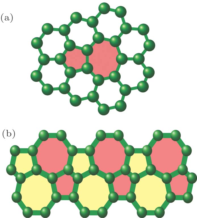
Fig. 1. (color online) Pentagon-heptagon defects in graphene lattice: (a) one pentagon-heptagon pair, (b) a structure completely consisted of pentagon-heptagon pairs.

Let tc denote the percolation threshold of the bond density t, at which an infinite cluster appears. For every value , there exists a gaint cluster connecting from the top to the bottom of the lattice, whereas for every , no such cluster exists.

In order to calculate the threshold, two representative methods are useful. One way is to derive nature of the model by analytical method. This method is not always available. The other way is to calculate tc by numerical method. For an infinite system hard to analyze, one can simulate finite systems on a computer, then to extrapolate the results to infinite system, i.e., taking the thermodynamic limit.

Further, one can use finite-size scaling[22] to analyze the transition property of the percolation. For continuous phase transition, any measurable quantity X near the critical point tc has a power-law form

where ω is a critical exponent. For a finite system of size L, measurable quantity X has a universal scaling form near the critical point:

where ν is another critical exponent that determines the universality class of the exponent. Here, F is a universal function. For example,

here is defined as the fraction of bonds in the largest cluster where the lattice has bond density t. β is also a critical exponent, which characterizes the percolation strength. Where , from Eq. (2), the quantity X will have a simple scaling form . By measuring X on various system size, one can obtain ratio of -ω/ν with fitting technique. Using and Eq. (2), one can obtain numerically universal function F, which is universal for any system size, includes infinite size. Here comes the most crucial step, the calculation of critical point tc. The higher the precision of the tc, the more reliable the numerical calculations. In fact, a good estimation of the critical point is the cornerstone of further calculations.

In the present paper, we use a new sampling technique to calculate the critical point. Let A be the property “There exists a cluster connecting from top of the lattice to the bottom, i.e., a percolating cluster”, and let be the percolating probability that the lattice with size of possesses the property A. Then the critical point tc is defined as a density value of bonds, such that

This definition permits one to obtain the critical point by sampling method rather than by following an evolution process. So, the calculation time may be short and the computational size may be large. This is significant for thermodynamics limit because the larger the size of the finite lattice, the closer the system is to infinity, at least, the more closer to Avogadro’s number (an infinite number in practice).

3. Simulations and results

In this section, we consider the numerical simulations of graphene lattice with defects. The lattice size is and L varies between 1000 and 3800 with a step length of 200. Three different values of concentration p of the defects are considered, 0, 0.5, and 1.

First of all, we shall confirm the rightness of our method by numerical simulation. To this end, a large number of simulations are made on graphene lattice without defect, i.e., the case of p = 0. Theoretically, for graphene bond-percolation, the critical point tc is ,[1] which approximates to 0.6527. Our simulations on various lattice sizes in the area show that the critical density of bonds is between t = 0.652 and t = 0.653. One of the two bond density is slightly smaller the theoretical critical point and the other is slightly bigger than the one.

In the following we hope to see two different trends in percolation probabilities. The simulation results (two curves in the middle) are shown in Fig. 2. We see that, with the increasing of lattice size L, a little change of the bond density will result two complete different trends of the percolating probability. One percolating probability has tendency towards 1 whereas the other 0. According to the definition (4), one will derive that the critical point locates in the interval (0.652,0.653). If we take the medium value of this interval as the critical point, i.e., 0.6525, it is very close to the analytical result[1] (0.6527). This confirms the rightness of our method. The further evidence is that the up middle line is flatter than the down middle line, which is originated from the analytical critical point is much closer to 0.653 than 0.652. The much closer to critical point, the more dramatic critical slowing down.

Fig. 2. (color online) The percolating probability obtained by simulations under four different concentrations of bond on graphene. Each data point is the average over 2000 independent and identically distributed realizations. Error bars indicate the standard deviation of many realizations (some error bars are too small to be seen).

Additional simulations are made on various lattice sizes, where densities of bonds are t = 0.649 and t = 0.656. The top line and the bottom line in Fig. 2 show the simulation results. As the density of bonds gets away from the critical point, the percolating probability changes drastically. When the density of bonds goes down to 0, the percolating probability fast tends to be 0 with the increasing of the lattice size. However, When the density of bonds goes up to 1, the percolating probability fast tends to be 1. From our simulation results, the trend is very obvious. The method is very sensitive to the change of the bond density. This means the method may have high precision in locating the critical point.

Back to our question for graphene lattice with defects. If defects appear with the probability 1, the lattice consists completely of pentagon–heptagon pairs. For simplicity, we consider a simple structure which is formed by regular permutations of pentagon–heptagon pairs (see Fig. 1(b)). Figure 3 shows the simulation results where t = 0.659 and t = 0.660. The percolating probability increases with increasing the lattice size at the bond density 0.660. However, it decreases with the increasing the lattice size at the bond density 0.659. The figure expresses distinctly that the critical point locates between 0.659 and 0.660. The breadth of the interval is so narrow that the maximum error of the position is 0.001. It is notable that the critical point in lattice completely consisted of pentagon-heptagon pairs is slightly different from the critical point in traditional honeycomb lattice.
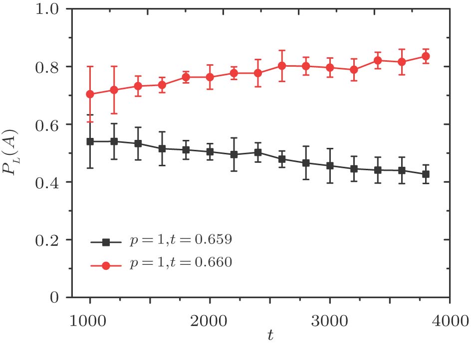
Fig. 3. (color online) The percolating probability under two kinds of densities of bond on graphene with defects of the concentration 1. Error bars represent standard deviation of many realizations.

What about the nature of percolation if the graphene lattice has a small ratio of defects? Since the two critical points discussed above are close to each other, a small ratio of defects in the graphene lattice will have a little affection on percolation properties. The numerical simulations are made when p = 0.5, which is a medium value of concentration 0 and 1. A large number of simulations on various lattice sizes tell us that the corresponding critical point is near to 0.6565, because the percolating probability has two different trends. It tends towards to 1 with increasing lattice size at bond density 0.657. Whereas it tends towards to 0 with increasing lattice size at bond density 0.656. This critical value is approximate to the average of 0.6527 and 0.6595 (the critical values at defect concentrations of 0 and 1). It implies that the concentration of the defects has nearly a linear affection on the percolation critical point.

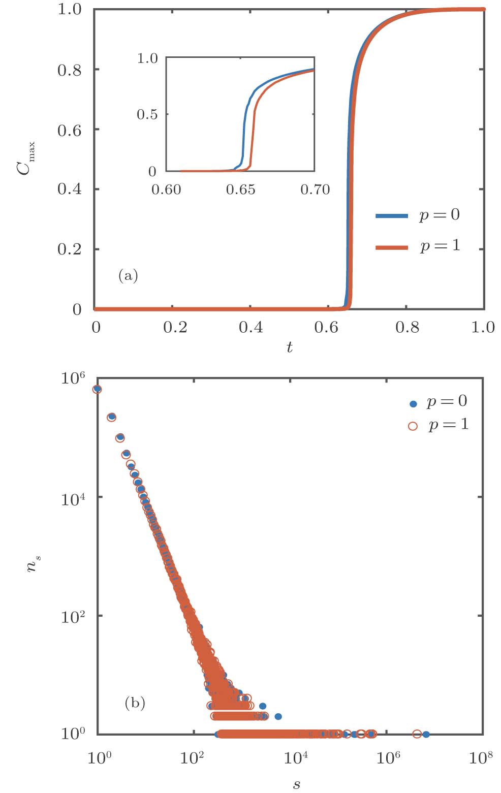
The relative size of the largest connected cluster, describing the probability of any node to be the member of the largest cluster, is the order parameter in percolation process. One can use order parameter to determine the order of the percolation transition. The cluster size distribution at the critical point also can be used to depict the characteristic of the percolation transition. In this way, a power law distribution is observed in typical continuous phase transition. We compare the evolutions of the largest connected cluster under p = 0 and p = 1. The cluster size distributions at critical point under two concentrations of defects are compared too.

Let be the relative size of the largest connected cluster, i.e., the size of the largest cluster divided by system size. By lots of observations, we find that

reduces to zero if we make the simulation on larger and larger system (to increase L). It shows that exhibits the property of self-averaging.[23] Therefore, we can simply investigate larger system with less statistically errors instead of doing average on independently identical distribution realization. Though the total computing time may be the same, it has advantage to study the evolution of quantity on a single larger system. For example, never decreases in the evolution process on a single system.

Figure 4 is the simulation results on the lattice size of 4000 × 4000, which shows the evolution of the quantity . We may conclude that the phase transitions under two concentrations of defects have similar behaviors except there is a little difference in position where it happens. On the other hand, the cluster size distribution is also similar at critical point, as shown in Fig. 4(b). In the same interval of the distributions, both distributions follow the same power law.

Fig. 4. (color online) The comparison of the evolution of the largest cluster size and the cluster sizes distribution, which are based on one realization on lattice size 4000 × 4000. (a) The normalized size of the largest connected cluster versus the bond density t. Inset shows the largest size evolution near the critical point. (b) The cluster size distribution at the critical point. The log–log plot of the number of cluster size versus size s.

In addition, the lattice with defects is still a two dimensional geometry structure, so the graphene lattice with or without defects falls into the same universality class.[1]

4. Conclusion

In this paper, we have studied in detail percolation property on graphene with pentagon-heptagon defects. By new sampling method, we have calculated accurately the percolation threshold of finite lattice, and deduced the percolation threshold of infinite lattice based on the simulation results on finite size lattice for several concentrations of defects. This method can be also used to locate the critical point on other types of lattice. Further, we calculate cluster size distribution and have found that the concentrations of defects has a little affection on percolation properties.

Reference
[1] Stauffer D Aharony A 2003 Introduction to Percolation Theory Taylor and Francis 5 13 52
[2] Callaway D S Newman M E J Strogatz S H Watts D J 2000 Phys. Rev. Lett. 85 5468
[3] Moore C Newman M E J 2000 Phys. Rev. E 61 5678
[4] Li M Wang B H 2014 Chin. Phys. B 23 076402
[5] Wan B H Zhang P Zhang J Di Z R Fan Y 2012 Acta Phys. Sin. 61 166402
[6] Kaminski A Das S S 2002 Phys. Rev. Lett. 88 247202
[7] Pastor-Satorras R Castellano C Van Mieghem P Vespignani A 2015 Rev. Mod. Phys. 87 925
[8] Li L Li K F 2015 Acta Phys. Sin. 64 136402 (in Chinese) http://wulixb.iphy.ac.cn/EN/abstract/abstract64525.shtml
[9] Li Z W Liu H J Xu X 2013 Acta Phys. Sin. 62 096401 (in Chinese) http://wulixb.iphy.ac.cn/EN/abstract/abstract53664.shtml
[10] Arda E Mergen Ö B Pekcan Ö 2018 Phase Transit. 91 546
[11] Bellaiche L Wei S H Zunger A 1996 Phys. Rev. B 54 17568
[12] Boulanger N Yu V Hilke M Toney M F Barbero D R 1996 Phys. Chem. Chem. Phys. 20 4422
[13] Franceschetti M Dousse O Tse D N C Thiran P 2007 IEEE T Inform. Theor. 53 1009
[14] Jia X Hon J S Yang H C Yang C Fu C J Hu J Q SHi X H 2015 Chin. Phys. Lett. 32 016403
[15] Balcan D Colizza V Gonçalves B Hu H Ramasco J J Vespignani A 2009 Proc. Natl. Acad. Sci. 106 21484
[16] Achlioptas D Souza R M D Spencer J 2009 Science 323 1453
[17] Zierenberg J Fricke N Marenz M Spitzner F P Blavatska V Janke W 2007 Phys. Rev. E 96 062125
[18] Mascioli A M Burke C J Giso M Q Atherton T J 2017 Soft Matter 13 7090
[19] Lončarević I Budinski-Petković L Dujak D Karašić A Jašić Z M Vrhovac S B 2017 J. Stat. Mech.-Theor. E 2017 093202
[20] Iliev G K Janse V R E J Madras N 2015 J. Stat. Phys. 158 255
[21] Lu M M Yuan J Wen B Liu J Cao W Q Cao M S 2013 Chin. Phys. B 22 037701
[22] Landau D P Binder K 2000 A Guide to Monte Carlo Simulations in Statistical Physics 2 Cambridge Cambridge University Press
[23] Binder K Heermann D W 2010 Monte Carlo Simulation in Statistical Physics 5 Berlin Springer 62