† Corresponding author. E-mail:
Project supported by the National Natural Science Foundation of China (Grant No. 61601149) and the Program for Changjiang Scholars and Innovative Research Team in University of Ministry of Education of China (Grant No. IRT_16R17).
In practical situations, large machinery is usually placed in an underwater vessel and changes the acoustic enclosure shape into an irregular one. The existence of machinery causes the difficulties in expressing sound transmission and radiation analytically. In this study, the sound radiation of a cylindrical shell excited by an internal acoustic source is modeled and analyzed. The cylindrical shell contains a machine modeled as a rectangular object, which is attached to a shell with a spring-mass system. The acoustic field of the cavity is computed by the integro-modal approach. The effect of object size on the coupling between acoustic mode and structural mode is investigated. The relationship between object volume and sound radiation is also studied. Numerical results show that the existence of objects inside vessels leads to a more effective coupling between the structure and acoustic enclosure than the existence of no objects in a regular-shaped cavity (i.e. empty vessel).
Water-loaded cylindrical enclosures are widely used as simple examples for demonstrating the acoustic characteristics of underwater vessels. Enclosures are usually constructed with relatively thin materials, and an important component of sound radiation is related to airborne noise inside these vehicles. Due to the existence of internal structures and machinery inside the vehicle, the enclosure is changed from a regular enclosure into an irregular-shaped enclosure. Subsequently, the characteristics of sound radiation from the vehicle become very complex. The analyzing of the noise transmitted through the enclosure walls is often problematic. Dowell[1] and Lyon[2] presented early models on vibration and cavity-backed plates. Narayanan[3,4] investigated sound transmission properties through a sandwiched panel and into a rectangular enclosure. Interior noise in an enclosure could be decomposed using an orthogonal expansion. Dowell[5] presented a comprehensive theoretical model based on the modal expansion theory and Green’s theorem to analyze the sound transmission characteristics of a panel with structural-acoustic coupling, then James[6] employed a similar approach for internally excited cylindrical shells. Fuller[7] presented the reasons behind the different transmission losses of a shell wall by analyzing theoretical values and experimental data from a previous research (see Morfey[8]). Further, Lee[9] analyzed the characteristics of sound transmission into a cylindrical shell through theoretical and experimental research.
In contrast to the empty cylindrical shell, the shell with internal structures and added mass seems to be a more realistic model. There is a considerable amount of literature dealing with the effects of rings,[10] rigid discs,[11] anechoic coatings,[12] and bulkheads.[13–15] In ships and submarines, internal structures and machinery are often mounted into hulls by using a type of resilient material that can isolate vibration. Approximately, the resilient material can be regarded as a spring system, and the internal structure as mass attached to it.[16,17] Guo[18] showed that the attachment of the simple spring-mass loading causes significant changes in the acoustic behavior of the shell. Titovich and Norris[19] extended the analysis by considering a cylindrical shell with an internal mass attached by multiple axisymmetrically distributed stiffeners.
In previous work, internal machinery was often regarded as an internal spring-mass system without considering its volume effect. In fact, the inner space of a shell becomes irregular because of the existence of machines, and the acoustic modes of the shell become difficult to express analytically. Missaoui and Cheng[20,21] proposed the combined integro-modal approach to handle irregular-shaped cavities, in which the interior acoustic field is simplified as either a model for regular sub-cavities or the boundary cavities with irregular-shaped boundaries. Despite the findings that geometric deformities of the cavity[22] or the internal structure inside an acoustic enclosure[23,24] can affect the structural-acoustic coupling between shells and their interior acoustic field, studies on the influence of machinery volume occupation on structural acoustic coupling remain limited. In practice, a machine has a finite size and, in most cases, occupies a large part of the vehicle interior space. Consequently, the existence of internal machineries affects the acoustic field inside the shell, thereby changing the vibration and sound radiation.
The purpose of the present study is to investigate the possible effects of machinery volume on the interior acoustic field and sound radiation of a submerged cylindrical shell excited by an internal monopole acoustic source.
The present work is to extend the previous model[25] by considering a finite shell containing a finite-sized mechanical machine modelled as a rectangular object. The integro-modal approach is adopted to deal with the irregular-shaped acoustic enclosure caused by the machine. Then a complex vibro-acoustic system is performed to discuss phenomena on the shell with an irregular-shaped acoustic enclosure. Although numerical methods are general and successfully used in the past to analyze irregular-shaped cavities and other models in the low-frequency range, it is clear that physical models establishment is necessary for parametric studies.[26] The rest of the present paper is organized as follows. The mathematical formulation is described in Section
A finite thin cylindrical shell with thickness h, radius R, length L, and in-vacuo bulk mass density ρs is considered for analysis. Considering a single cylindrical section, the shell bulkheads are simplified into two rigid end plates (to form a finite cylinder for the internal acoustic field) attached to two semi-infinite rigid baffles to prevent the sound from transmitting between compartments.[27,28] A mechanical machine is modeled as a rectangular box with a square cross section and a slightly shorter length than the shell to avoid end-plate influence. The box with a rigid boundary and mass M is attached to the inner surface of the shell by continuous springs, each with stiffness κ (unit of force per unit area). The cylindrical coordinate system used for analysis is shown in Fig.
 | Fig. 1. Geometry and coordinate system of a cylindrical shell, showing (a) finite cylindrical shell with semi-infinite baffles and (b) cross-section of shell with monopole source. |
Consider a harmonic motion, the radial displacement of the shell, w, is coupled to the other two displacement components, namely, u in the axial direction and v in the circumferential direction, through dynamic equations for shell vibrations. Donnell’s thin shell equation[29] is used to describe the equations of motion of the cylindrical shell. The equation is written as follows:


The displacement function of the shell is simply supported on its end, which is satisfied with boundary conditions, can be expanded using modes as follows:

The pressure field outside of the shell is written as[30–32]


The spring-mass system is connected to the shell as shown in Fig.


With the consideration of the machine size, the acoustic enclosure of the shell becomes irregular. For the irregular-shaped enclosure, the internal pressure is handled by using the integro-modal approach.[20,21] In the method the whole cavity is discretized into a series of sub-cavities, whose acoustic pressure is simplified as either over a modal basis of regular sub-cavities or over that of the bounding cavities in the case of irregular-shaped boundaries. In the present paper a point source item is introduced into the integro-modal formulation to analyze the influence of the internal object.
Green’s theorem together with the Helmholtz equation is used for describing the interior sound pressure


Considering the weak contribution of internal object motion in the internal acoustic field, the boundary condition of the object is simplified into being rigid. The equations for the boundary conditions at the walls of the cavity can be written as


The internal pressure is decomposed using an orthogonal expansion in terms of the rigid-walled acoustic modes of rectangular cavities as shown in Fig.


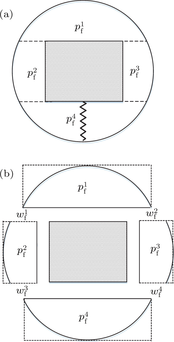 | Fig. 2. Discretization procedure using the integro-modal approach, showing (a) the real cavity and (b) four decomposed sub-cavities. |
The transverse displacement of the virtual membranes is also expanded in terms of in-vacuo normal mode shapes 


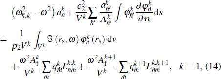


So far, all the structural and acoustic subsystems have been formulated. The final matrix equations based on Eqs. (

In order to analyze the effect of internal objects on the characteristics of the interior acoustic field and the sound radiation, a finite cylindrical shell is taken for an example. The numerical analysis is performed for the parameter values of the vibro-acoustic system gathered in Table
The internal object, which occupies a volume Vb (a × a × L) with rigid boundary, is attached to the inner surface of the shell by continuous springs with stiffness κ. The mass-spring system parameter is chosen as the ratio of internal mass to shell mass M/2πρshRL = 3, and the spring constant κ is chosen as
| Table 1. Physical parameters of vibro-acoustic system. . |
The truncation of the decomposition series is a factor affecting the accuracy of the calculation. Roughly speaking, the 

 | Fig. 3. (color online) Comparisons among curves of sound pressure level versus frequency for different decomposition terms. |
Besides, equation (
| Table 2. Resonant frequencies of irregular cavity with β = 0.5 using different methods. . |
The coupling analysis between the shell and interior acoustic field due to the variation of β is first investigated. In the case of β = 0, the enclosure is a regular cylindrical cavity. Due to the perfect symmetry of the system, a structural mode is coupled to an acoustic mode in a very selective manner.[24] For the coupled shell-cavity system, the coupling coefficient between the 


It can be seen that the coefficients of the Fourier series expansion are complicated by the analytical solution. The most convenient method of evaluating the equation is to integrate numerically along the inner surface of the shell. Like the general asymmetric structure, the irregularity of the enclosure can lead to the coupling between each order acoustic mode and structural mode.
The existence of the object changes the regular-shaped cavity into an irregular one, and subsequently exerts an influence on the internal acoustic field. An average quadratic pressure is defined inside the enclosure as


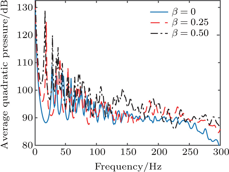 | Fig. 4. (color online) Curves of average quadratic pressure versus frequency inside the shell with different values of β. |
To discuss the relationship between resonant peak and the object size, figure
Further analysis is made to identify contributions of the object size to the eigenfrequency. Despite the lack of symmetry in the cross-section area, the irregular cavity can still be expanded among modes with different longitudinal orders. The average quadratic pressures are shown in Figs.
 | Fig. 6. (color online) Curves of average quadratic pressure versus frequency for different values ofβ with nz = 0 (a) and nz = 2 (b). |
For a regular-shaped cavity, equation (
 | Fig. 7. (color online) Acoustic pressure distributions on the cross section (a) first peaks; (b) second peaks. |
In addition to the volume occupation, the shape of the object is another very practical factor. Figure
The effect of the object volume occupation on the internal acoustic field will further cause the vibration response of the shell to change. The average quadratic velocity of the structure is defined as a physical quantity describing the vibration characteristics as follows:


Figure
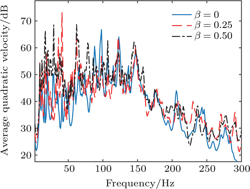 | Fig. 9. (color online) Variations of average quadratic velocity with the frequency of the shell for different values of β. |
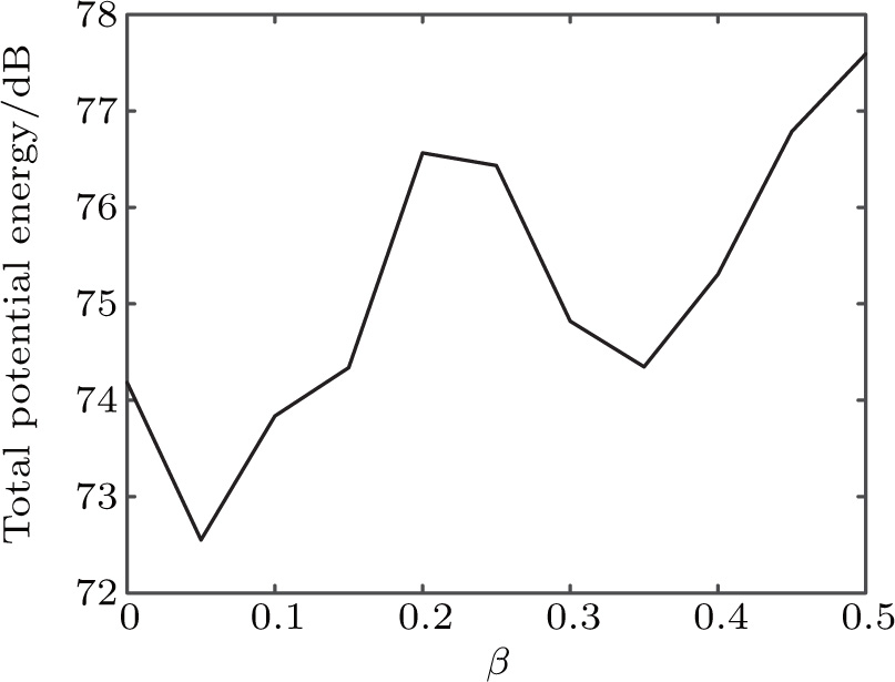
In order to study the general trend of structural characteristics affected by the internal object occupation, the total kinetic energy of structural vibration is also analyzed below the ring frequency. Figure
In applications, radiated sound power is an important parameter in vibro-acoustic response prediction, which reflects the radiated energy of the structure excited by internal machinery. Like the case with average quadratic pressure inside the cylindrical shell, the first few resonant peaks of the radiated sound power are shifted to the low frequency with the object volume increasing in Fig.
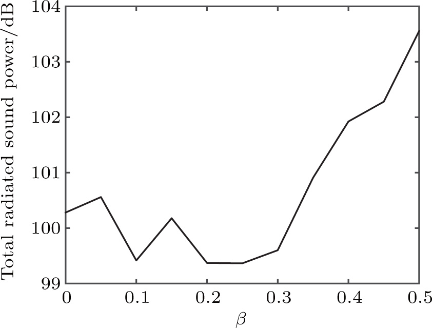
The total sound power below ring frequency is given in Fig.
Further analysis is made to identify contributions of the object size to the sound radiation which can be expanded among modes with different circumferential orders in Figs.
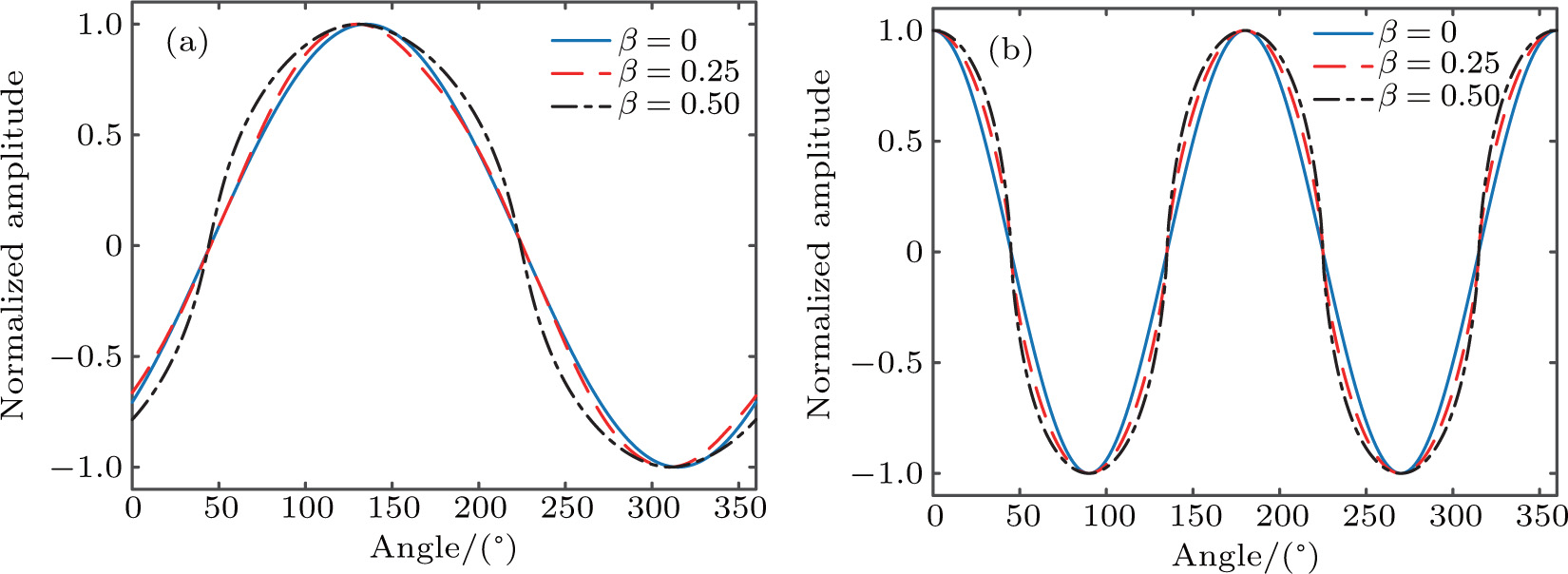
Far-field directivity is useful and instructive not only because it shows the spatial distribution of radiated acoustic energy, but also because it reflects the nature of the radiated acoustic energy which produces the radiation. Due to the sharp peaks and dips of the far-field pressure which varies with frequency, the results at a single frequency may not reflect the true nature of the radiated field. Figure
The structural-acoustic coupling characteristics of a submerged finite cylindrical shell with irregular-shaped acoustic enclosure are investigated. Due to the existence of an internal object, the sound transmission and radiation process involve a complex structural-acoustic coupling. Numerical simulations are conducted to determine the relationship between object size and shell behavior. The main conclusions can be drawn as follows.
The existence of an internal object changes the cavity from a regular- into an irregular-shaped enclosure. The pressure distribution inside the cavity is sensitive to geometrical changes. The internal object affects the resonance frequencies of the enclosure and corresponding mode shapes. The resonant frequencies of the first few natural modes shift to the low frequency as object volume increases. The relationship between resonant frequencies and spatial scale, which is generally applicable to regular cavities, is not always suitable for those with irregular shapes. Furthermore, irregularity can enhance the structural-acoustic coupling between different modes.
The influence of object volume on vibration is mainly reflected by the change in structure response in the low-frequency range, especially with respect to vibration strength. This phenomenon is evidently caused by the change of internal acoustic excitation. As frequency increases, the change in structural response decreased gradually for different object sizes. The change in the total average quadratic velocity is less than 6 dB below the ring frequency.
Unlike structural vibration, the contribution of the object volume occupation to sound radiation is mainly the distribution of resonance peaks, while the effect is non-significant on energy radiation. Given that only a part of the sound energy can effectively pass through the shell and into the external fluid, the sound radiation is less affected by object volume occupation than the interior acoustic field. In addition, object volume occupation enhances the directivity of far-field pressure in the low-frequency range.
| [1] | |
| [2] | |
| [3] | |
| [4] | |
| [5] | |
| [6] | |
| [7] | |
| [8] | |
| [9] | |
| [10] | |
| [11] | |
| [12] | |
| [13] | |
| [14] | |
| [15] | |
| [16] | |
| [17] | |
| [18] | |
| [19] | |
| [20] | |
| [21] | |
| [22] | |
| [23] | |
| [24] | |
| [25] | |
| [26] | |
| [27] | |
| [28] | |
| [29] | |
| [30] | |
| [31] | |
| [32] | |
| [33] |


