† Corresponding author. E-mail:
Project supported by the National Natural Science Foundation of China (Grant Nos. 61575170, 61575168, and 61475133), the Basic Research Project of Hebei Province, China (Grant No. 16961701D), the Natural Science Foundation of Hebei Province, China (Grant No. F2016203392), the Provincial College and University Natural Science Foundation of Hebei, China (Grant No. QN2016078), and the Intramural Doctoral Foundation of Yanshan University, China (Grant No. B1011).
The optical properties of graphene coated D-shaped single mode fiber and photonic crystal fiber are numerically analyzed. Enhancement of the graphene-light interaction is found in graphene coated D-shaped photonic crystal fiber, which introduces a tunable polarization of the D-shaped fiber by changing the chemical potential of the coated graphene. An optimal polarizer model is demonstrated with the extinction ratio of 66.26 dB/mm and the insertion loss of 9.4 dB/mm. The modulator extinction ratios of the TE mode and TM mode are 11.5 dB and 5 dB, respectively, with a device length of 100 μm. This paper provides a theoretical reference for the optical property research of the graphene fiber.
Graphene is attracting worldwide attention due to its unique electronic and photonic properties, such as high quantum efficiency for light-matter interactions, high carrier mobility, zero bandgap, gate-variable optical conductivity, ultra-broadband saturable absorption, and nonlinear optical Kerr effect, which have led to demonstrations of a number of graphene-based fiber devices,[1–3] such as polarizers, saturation absorbers, modulators, switches, photo-detectors, and so on. The graphene-light interaction is limited by a large area of cladding layer for single mode fiber (SMF). The enhancement of graphene-light interaction remains a challenge for many graphene-based photonic devices. Different geometric structures, including polish and taper, have been proposed to efficiently enhance the light-graphene interaction.[4–7]
In this paper, we explore the transmission characteristics of a graphene coated D-shaped fiber and find that a largely enhanced light-graphene interaction is induced by the strong evanescent field of the D-shaped SMF and D-shaped photonic crystal fiber (PCF). It is demonstrated that by employing multi-layer graphene, the light-graphene interaction and modulation effect can be greatly enhanced, which provides theoretical guidance for future experiments.
Graphene, a two-dimensional crystal material, is a single atomic layer of sp2-hybridized carbon forming a honeycomb crystal lattice.[8] The hexagonal honeycomb lattice of graphene, with two carbon atoms per unit cell, leads to a rather unique band structure. The bottom conduction band and the top valence band touch at six points, the so-called Dirac points, and there is no energy bandgap, which can be viewed as two cones touching at the Dirac point. This unique band structure determines the simultaneous existence of interband and intraband transitions. Therefore, the conductivity of graphene is described by interband and intraband contributions, with its conductivity given by the Kubo formula[9]


Polarizers are indispensable key optical components in optical communication systems, which can realize the conversion and switching of the polarization state. An electro regulation polarizer model based on graphene coated D-fiber is proposed by controlling the Fermi level of graphene. The complex effective refractive index is used to illustrate the optical characteristics of graphene coated D-fiber, and the imaginary part of the effective refractive index is k, the absorption coefficient is α, the limiting loss is Losslimit, the insertion loss is Lossinsert, and the polarization extinction ratio is σPER,[12,13] which are described by the following equations:


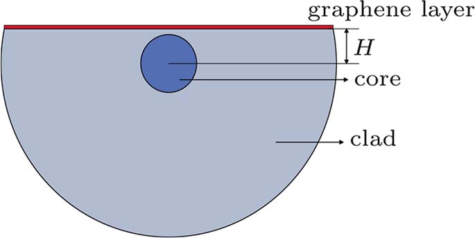
The cross-section of graphene-coated D-shaped single-mode fiber is shown in Fig.
The polishing depth of a single-mode fiber directly determines the distribution of the evanescent field of the fiber. First, the influence of different polishing depths on the light transmission with a single-layer of graphene coating is studied. Figure
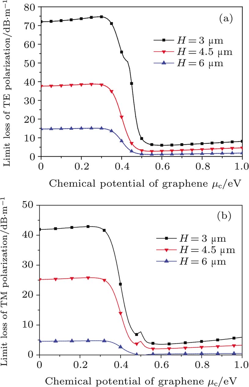 | Fig. 2. (color online) Limit loss characteristics of the monolayer graphene coated D-shaped SMF with different polishing depths. (a) TE mode loss. (b) TM mode loss. |
The limit loss increases with the polishing depth because there is more leakage of light, and the transmission loss of the TE mode is greater than that of the TM mode under the same polishing depth with a single-layer graphene coating due to more light absorption to the TE mode. In the TM mode, the peak of loss appears near the zero point (0.5 eV) of the dielectric constant and increases with the increase of the polish depth, but it is not confirmed in the TE mode. It is proved that graphene has played a role in fiber transmission. At H = 4.5 μm, for the TE mode, the maximum loss is 38.68 dB/m and the minimum loss is 2.8 dB/m, while for the TM mode, the maximum loss is 25.81 dB/m and the minimum loss is 2.06 dB/m. The real part of the effective refractive index has little change with the increase of the chemical potential under the same polishing depth and decreases with the increase of the polishing depth, as shown in Table
| Table 1. Real part of the effective refractive index. . |
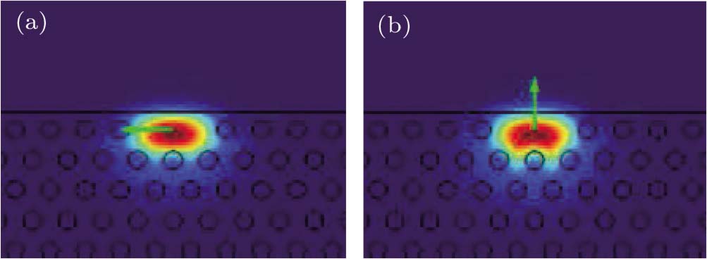
With a flexible structure and independence on the temperature, photonic crystal fiber is being explored for more and more applications.[15,16] The cross-section of graphene coated D-shaped PCF is shown in Fig.
The limit loss of the TE mode and TM mode as a function of polishing depth of H = 0.5Λ (just polished to the edge of the core), H = 0.62Λ (just part of the core section is polished), and H = 0.95Λ (core is not polished) is shown in Fig.
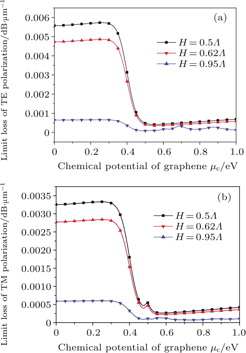 | Fig. 5. (color online) Limit loss as a function of the chemical potential for D-PCF with different polishing depths of (a) TE mode and (b) TM mode. |
Figure
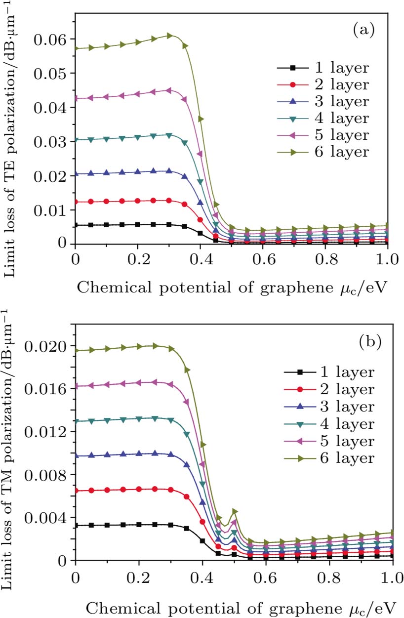 | Fig. 6. (color online) Limiting loss of graphene as a function of the chemical potential for PCF with different air hole layers for (a) TE mode and (b) TM mode. |
When the polishing depth and the number of graphene layers are fixed, i.e., H = 0.5Λ and four layers, figure
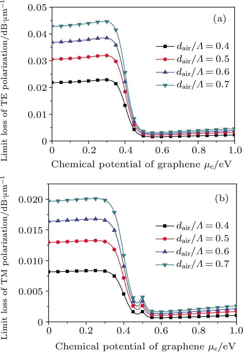 | Fig. 7. (color online) Limit loss as a function of the chemical potential for different structures of PCF for (a) TE mode and (b) TM mode. |
Figure
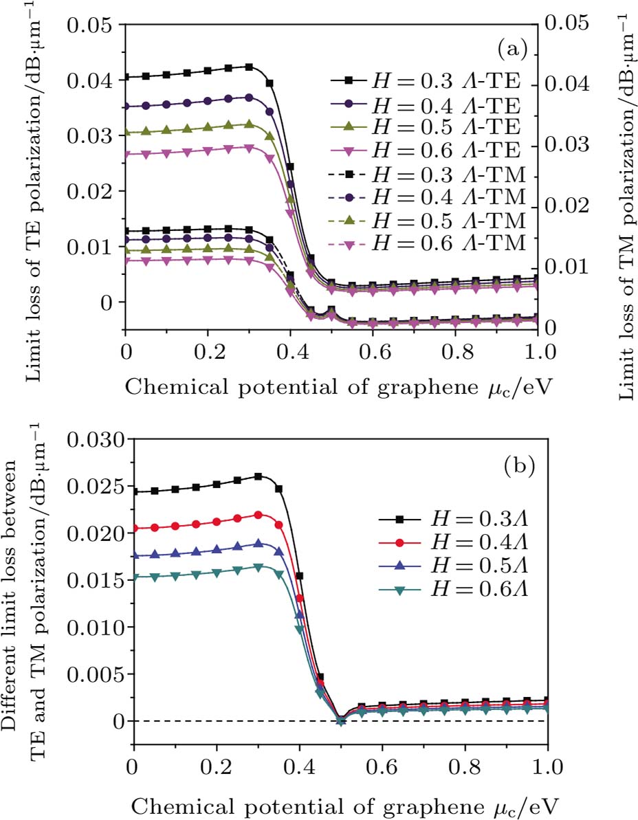 | Fig. 8. (color online) (a) Limit loss with different polishing depths for TE mode and TM mode, and (b) the difference of limit loss between TE and TM modes as a function of the chemical potential. |
It can be found that for the D-shaped PCF coated graphene layer structure, the more graphene layers there are, the greater the air hole/space ratio, the greater the polishing depth, and the more advantageous the polarizer design. However, the number of layers is limited by the insertion loss of the device. When the number of graphene layers is more than 10, the minimum value of loss is larger. When the number of graphene layers increases by 20, the buffer layer structure weakens the ability of the optical fiber to restrict light so much that the light cannot propagate inside the optical fiber core.
From the numerical analysis, a polarizer based on graphene coated D-shaped photonic crystal fiber is designed. The structural parameters of graphene coated D-shaped photonic crystal fiber are that the polishing depth is H = 0.4Λ, and the air hole/space ratio is 0.8. The polarizer is a TM mode polarizer, since only the TM polarized light can pass through the polarizer in the “ON” status, when the difference between TE mode and TM mode is the largest. The loss difference at 0.3 eV achieves 0.03313 dB/μm, the minimum loss difference at 0.51 eV is 7 × 10⁻⁵ dB/μm, the polarization extinction ratio of this device achieves 66.26 dB/mm, and the insertion loss is 9.4 dB/mm. The device length is 70.31 μm < L < 151.64 μm decided by the transmission formula[19]Lmax = λ/(4π · Im(neff)), and the graphene chemical potentials at work status “on” and “off” are 0.3 eV and 0.51 eV, respectively.
If only the TM light is launched into the fiber, the device is a TM polarization modulator. The TM mode is turned off at a chemical potential of 0.25 eV with a transmission loss of 0.02902 dB/μm, and turned on at a chemical potential of 0.47 eV with a minimum transmission loss of 0.00445 dB/μm, and this TM modulator has an extinction ratio of 5 dB with a device length of 100 μm and an insertion loss of 0.9 dB. If only the TE light is launched into the fiber, the device is a TE polarization modulator. The TE mode is turned off at a chemical potential of 0.28 eV with a maximum transmission loss of 0.06186 dB/μm, and turned on at a chemical potential of 0.56 eV with a minimum transmission loss of 0.0043 dB/μm, and this TE modulator has an extinction ratio of 11.3 dB with a device length of 100 μm and an insertion loss of 0.86 dB.
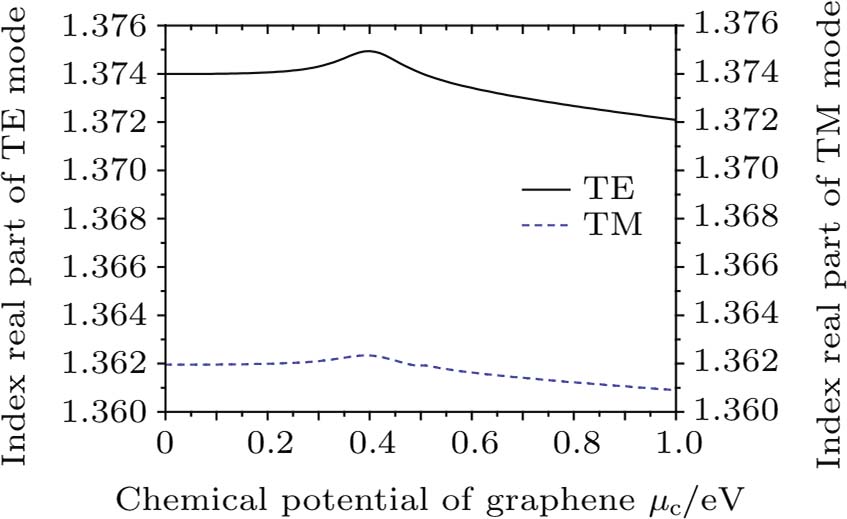
Figure
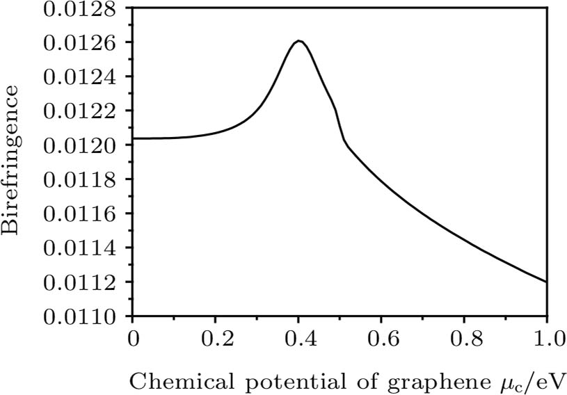
The difference between the real part of the effective refractive index of the TE mode and TM mode generates a birefringence effect, which also first increases to the maximum and then decreases with the increase of the chemical potential, as shown in Fig.
Figure
In this paper, a polarizer based on graphene coated D-shaped photonic crystal fiber is proposed. From the numerical analysis of the impact of structural changes of the photonic crystal fiber geometry parameters, the number of the graphene layer, and the polishing depth on the TE mode and TM mode, the optimal polarizer model is demonstrated with an extinction ratio of 66.26 dB/mm, the insertion loss reaches 9.4 dB/mm when the polishing depth is H = 0.4Λ, the number of the graphene layer is four, and the air-hole/space ratio is 0.8. The TE mode modulator extinction ratio achieves 11.5 dB and the TM mode modulator extinction ratio is 5 dB when the device length is 100 μm.
| [1] | |
| [2] | |
| [3] | |
| [4] | |
| [5] | |
| [6] | |
| [7] | |
| [8] | |
| [9] | |
| [10] | |
| [11] | |
| [12] | |
| [13] | |
| [14] | |
| [15] | |
| [16] | |
| [17] | |
| [18] | |
| [19] | |
| [20] |


