Pressure dependent modulation instability in photonic crystal fiber filled with argon gas*

Project supported by the Natural Science Foundation of Zhejiang Province, China (Grant No. LY15F050010) and the National Natural Science Foundation of China (Grant Nos. 11604296, 11404286, and 61727821).

Wang He-Lin1, 2, †, Yang Ai-Jun2, ‡, Wang XiaoLong1, Wu Bin1, Ruan Yi1
Center for Optics & Optoelectronics Research, Zhejiang University of Technology, Hangzhou 310023, China
College of Science, Zhejiang University of Technology, Hangzhou 310023, China


† Corresponding author. E-mail: whlin@zjut.edu.cn yangaij2004@zjut.edu.cn

Project supported by the Natural Science Foundation of Zhejiang Province, China (Grant No. LY15F050010) and the National Natural Science Foundation of China (Grant Nos. 11604296, 11404286, and 61727821).

Abstract

By using the designed photonic crystal fiber filled with argon gas, the effect of gas pressure on modulation instability (MI) gain is analyzed in detail. The MI gain bandwidth increases gradually as the argon gas pressure rises from 1P0 to 400P0 (P0 is one standard atmosphere), while its gain amplitude slightly decreases. Moreover, the increase of the incident light power also results in the increase of MI gain bandwidth in the Stokes or anti-Stokes region when the incident power increases from 1 W to 200 W. Making use of the optimal parameters including the higher argon gas pressure (400P0) and the incident light power (200 W), we finally obtain a 100 nm broadband MI gain. These results indicate that controlling the MI gain characteristic by changing the argon gas pressure in PCF is an effective way when the incident light source is not easy to satisfy the requirement of practical application. This method of controlling MI gain can be used in optical communication and laser shaping.

1. Introduction

Modulation instability (MI) process has been observed and studied in some fields, such as fluid dynamics, nonlinear optics, and plasma physics.[13] The physical mechanism of MI is the interplay between the nonlinear and dispersive effects. Although MI may bring some negative effects into some systems such as optical communication, it can also be useful. In the optical field, MI plays an essential role in four-wave mixing (FWM) process, wavelength conversion, and optical amplification. And it has been used to produce optical pulse trains[4] and optical solitons,[5] make MI laser,[6] and supercontinuum (SC) generation.[7] For the fiber, our previous research results show that the MI gain mainly depends on the fiber dispersion, the fiber nonlinearity, and stimulate Raman scattering.[810] Among them, the Raman scattering effect is mainly determined by the fiber substrate material (for example, fused silica), which is not easy to change once fiber is made. Thus, in order to manipulate the MI gain in experiment effectively, it is convenient to adjust the fiber structure or its refractive index distribution for controlling the fiber dispersion and nonlinearity.

Compared with the ordinary step-index fiber, the photonic crystal fiber, as a microstructure fiber, has an advantage of the flexible structural design,[11,12] which makes it easy and effective to obtain a tunable MI gain. Considering the photonic crystal fiber (PCF) dispersion and nonlinearity depending on the fiber structure, a tunable MI gain is usually obtained by changing the geometry structure of PCF or choosing the different incident light based on the fiber zero dispersion wavelength (ZDW). Although these methods are feasible theoretically, they not only waste more time but also increase the experimental cost. One reason is that some commercial light sources satisfying the experimental requirement are not easy to find in practice, especially for a light source with a high power and a tunable wavelength. The other reason is that the ZDW of PCF is invariable once it is made, which cannot be used to obtain a tunable MI gain. In this work, based on the existing commercial light source with a high output power, we will firstly fill the argon gas into the PCF, and study the pressure-dependent tunable MI gain characteristic by varying the pressure of argon gas in the PCF, which can control the PCF dispersion and nonlinearity conveniently.

2. MI gain theory in argon-filled PCF

For a non-birefringence photonic crystal fiber, the MI gain expression can be obtained by adding small perturbations into the steady solution of the scalar nonlinear SchrÖdinger equation (NLSE), which includes the nonlinear effects such as fiber dispersion, self-phase modulation (SPM), self-steepening (SS), stimulated Raman scattering (SRS), and four-wave mixing (FWM). It is written as[13]

where ξ = Ω/ωp, Ω = ωpωs = ωasωp (Ω > 0) is the detuning frequency, ωp is the angle frequency of the incident light, while ωas and ωs are the angle frequencies of the generated anti-Stokes and Stokes waves in the PCF; γ = n2ωp/cAeff is the nonlinear coefficient; n2 is the nonlinear refractive index of fused silica; Aeff is the effective mode area of the PCF fiber; Pp is the incident light power; D(Ω) = Σβ2nΩ2n/(2n)! (n ≥ 1), with β2n being the even order dispersion coefficients of the PCF and able to be calculated with a fiber transmission constant βn = nβ (ω)/ωn|ω = ωp; and R(Ω) is the Fourier transform of Raman response function R(t). It is noted that the fiber nonlinearity γ and the dispersion D(Ω) depend on the refractive index of the fiber core and the gas hole in the fiber. Here the fiber core is made of fused silica, while the gas hole is filled with the argon gas, whose refractive index can be controlled by changing the argon gas pressure. The refractivity of argon gas under pressure p can be written as[14]
where the subscript s refers to the standard conditions (t = 20 °C and p = 101325 Pa), (nAr ∡ 1)s has been precisely measured by Peck and Fisher, and it can be written as[15]
DAr,t,p is the density factor of argon gas and it can be calculated from
where p and t are in units of Pa and °C.

3. Pressure dependence MI gain property in argon-filled PCF

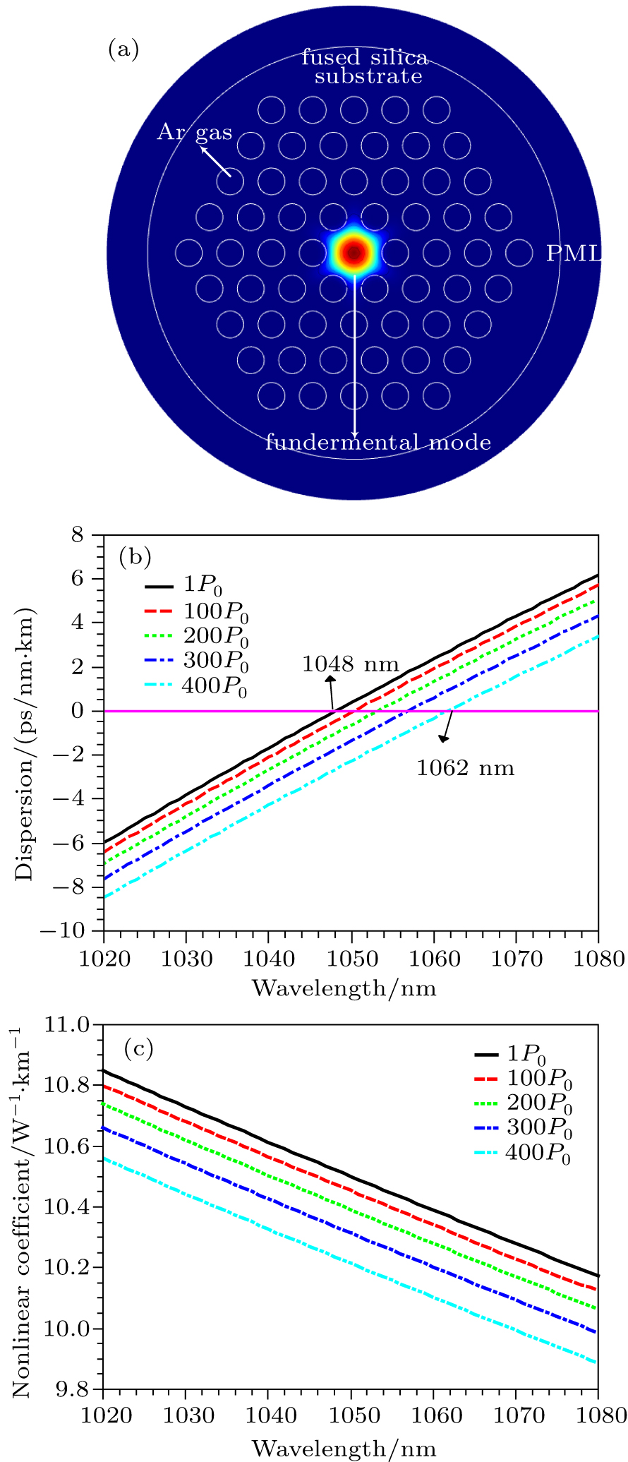
For studying the effect of argon gas on MI gain, a fused silica PCF filled with argon gas is designed with finite-difference frequency-domain techniques. Figure 1(a) shows the structure and the fundamental mode of the designed PCF filled with the argon gas. The fiber substrate material is fused silica, and the air hole is filled with argon gas. The PML indicates a perfectly matched layer. The pitch and radius of the fiber hole are 4 μm and 2.6 μm, respectively. By simulating the material dispersion and waveguide dispersion of the PCF, the total dispersion of the argon-gas-filled PCF is obtained as shown in Fig. 1(b). When the gas pressure is changed from 1P0 to 400P0 (P0 is one standard atmosphere), the zero dispersion wavelength of the PCF fiber is shifted from 1048 nm to 1062 nm (see Fig. 1(b)) with the increase of the gas pressure, while its nonlinearity decreases gradually at the same wavelength (see Fig. 1(c)). Based on our previous work and Eq. (1), one can see that the MI gain depends on the fiber dispersion, which can be tuned by changing the argon gas pressure in the PCF. Thus, one can regulate the fiber dispersion by controlling the gas pressure and then obtain a tunable MI gain. Here the incident wavelength is chosen to be 1064 nm, because the light source is a commercial product and its output power can reach 3000 W.

Fig. 1. (color online) Structure and properties of the designed PCF fiber filled with argon gas at different pressures: (a) fiber structure and its fundamental mode field, and variations of (b) fiber dispersion and (c) nonlinearity with wavelength.

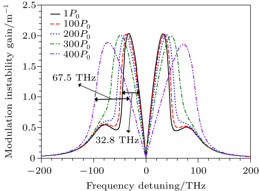
Figure 2 shows that the MI gain varies with the detuning frequency Ω for different argon gas pressures ranging from 1P0 to 400P0 and the light power is 100 W. It indicates that the MI gain bandwidth increases gradually with the increase of the gas pressure. For example, the full width at half maximum (FWHM) of MI gain spectrum is 32.8 THz at pressure 1P0, while it increases to 67.5 THz at pressure 400P0. Moreover, when the gas pressure is below 300P0, there are two gain peaks in the Stokes or anti-Stokes region. However, when the gas pressure is above 300P0, the two gain peaks merge into a gain peak, and a wide gain bandwidth is generated. It is interesting that the two gain peaks in the Stokes and anti-Stokes region are of symmetric distribution. Further analyzing Fig. 2, one can also find that the MI gain amplitude decreases gradually with the increase of the gas pressure. The reason is that the incident light energy is transferred to more detuning frequency components, which results in the increase of MI gain bandwidth and the decrease of gain amplitude. As a whole, these results indicate that controlling the MI gain by adjusting the gas pressure in the PCF is effective, and it provides a simple way to improve the MI gain.

Fig. 2. (color online) MI gain variations with frequency detuning for different gas pressures with pump power fixed at 100 W.

In the above section, we mainly discussed the effect of gas pressure on the MI gain bandwidth and amplitude at pump power Pp = 100 W. The following part will analyze the influences of the incident power on the MI gain at different gas pressures. Figure 3 shows the variations of the sideband wavelength with the incident light power. To express the MI gain more clearly, the color bar is used to represent the normalized MI gain. One can see from Fig. 3 that with the increase of the incident light power (from 1 W to 200 W), the gain peak in the Stokes or anti-Stokes region is gradually away from the incident wavelength (1064 nm), but their gain bandwidths widen gradually. The changing trend is most obvious at the gas pressure p = 400P0 especially, and the gain bandwidth reaches a maximum value at pump power Pp = 200 W. All figures manifest that an optimal MI gain with a wide bandwidth and a high gain can be obtained by optimizing the incident power and the gas pressure simultaneously.
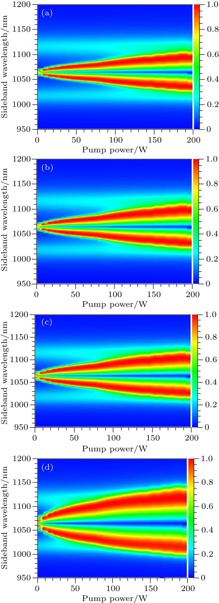
Fig. 3. (color online) Variations of MI sideband wavelength with incident power at different gas pressures: (a) 100P0, (b) 200P0, (c) 300P0, (d) 400P0.

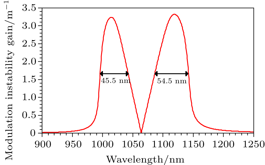
The former analysis reveals that the optimal incident power and the argon gas pressure may be set to be 200 W and 400P0 respectively for obtaining a broadband MI gain. Using the two optimal parameters, the optimal MI gain spectrum is obtained finally and shown in Fig. 4. One can see from Fig. 4 that the optimal gain bandwidth and amplitude reach 100 nm (45.5 nm in the anti-Stokes region plus 54.5 nm in the Stokes region) and over 3 m−1, respectively. It should be pointed out that here the incident wavelength is set to be 1064 nm, which can be delivered by a commercial light source with a high and tunable power, during the simulation, which is close to the designed fiber ZDW (1062 nm). It is different from our previous work[13] where the incident light source is chosen to be variable while the fiber parameters are invariable once it is made successfully. Actually, the MI gain is difficult to achieve by changing the incident light wavelength and the cost is usually expensive, because not all incident light sources with a broadband and tunable wavelength can be found in the commercial field. Even if you can find them, their price is usually high. The problem can be solved effectively by shifting the fiber ZDW close to the emission wavelength of a commercial light source based on the variation of the gas pressure. Moreover, the fiber dispersion and its nonlinearity can be tuned effectively by changing the gas pressure. The two fiber parameters have an important influence on the modulation instability gain, so using the gas-filled PCF to gain a tunable MI gain is practical for experiment, which can overcome the limitation of obtaining an adjustable fiber dispersion and nonlinearity by changing the fiber structure. Therefore, this research work can solve the problems efficiently and it is valuable in practice.

Fig. 4. (color online) Optimal gain bandwidth at argon gas pressure 400P0 and incident light power 200 W.
4. Conclusion

Based on the designed PCF fiber filled with argon gas, pressure- and power-dependent MI gain is studied. The results show that it is effective to control the MI gain bandwidth and amplitude by changing the incident power and the argon gas pressure in the PCF fiber. When the gas pressure increases from 1P0 to 400P0, the MI gain bandwidth increases gradually while its gain amplitude decreases slightly. Besides, the incident light power also has an important effect on the MI gain. The MI gain peak in the Stokes or anti-Stokes region strays from the incident wavelength (1064 nm) gradually when the incident power increases from 1 W to 200 W, and their gain bandwidths also gradually widen. These results indicate that it is a feasible way to gain a tunable MI gain by changing the argon gas pressure when the incident light source is difficult to satisfy the requirement, and the PCF fiber with an appropriate ZDW cannot be made. And it may be useful in the fiber laser, fiber communication, and fiber sensor in the future.

Reference
[1] Agrawal G 2013 Nonlinear Fiber Optics 5 New York Academic Press
[2] Golovchenko E A Pilipetskii A N 1994 J. Opt. Soc. Am. 11 92
[3] Abdullaev F K Darmanyan S A Kobyakov A Lederer F 1996 Phys. Lett. 220 213
[4] Hong W P 2002 Opt. Commun. 213 173
[5] Palacios S L Fernandez-Diaz J M 2000 Opt. Commun. 178 57
[6] Ylvestre T S Coen S Emplit P et. al. 2002 Opt. Lett. 27 482
[7] Roy S Chaudhuri P R 2009 Opt. Commun. 282 3448
[8] Wang H Yang A Leng Y 2014 Laser Phys. 24 035101
[9] Wang H Yang A Leng Y 2013 Laser Phys. 23 075102
[10] Wang H Yang A Leng Y 2013 Chin. Phys. 22 074208
[11] Kudlinski A Bendahmane A Labat D Virally S Murray R T Kelleher E J R Mussot A 2013 Opt. Express 21 8437
[12] Azhar M Wong G K L Chang W Joly N Y Russell P St J 2013 Opt. Express 21 4405
[13] Wang H L Leng Y X Xu Z Z 2009 Chin. Phys. 18 05375
[14] Zhang J Lu Z H Wang L J 2008 Appl. Opt. 47 3143
[15] Peak E R Fisher D J 1964 J. Opt. Soc. Am. 54 1362