Project supported by the Project for the State Key Laboratory of Optoelectronic Materials and Technologies of China (Grant No. 09010-32031708) and the Project for Zhuhai Key Laboratory of Center for Space Technology of China (Grant No. 71000-42080001).
Project supported by the Project for the State Key Laboratory of Optoelectronic Materials and Technologies of China (Grant No. 09010-32031708) and the Project for Zhuhai Key Laboratory of Center for Space Technology of China (Grant No. 71000-42080001).
† Corresponding author. E-mail:
Project supported by the Project for the State Key Laboratory of Optoelectronic Materials and Technologies of China (Grant No. 09010-32031708) and the Project for Zhuhai Key Laboratory of Center for Space Technology of China (Grant No. 71000-42080001).
To develop the application of fiber Bragg gratings as temperature and strain sensors in space environments, it is necessary to understand the effect of high-energy radiation on the performance of the fiber Bragg grating. We performed an experiment involving Co60-γ ionizing irradiation with a total dose of 1.01 × 10⁶ rad on two Ge-doped single-mode fiber Bragg gratings with central wavelengths of 825 and 835 nm, respectively. We found that, with the increase of radiation dose, the redshift of the peak wavelength of the reflection spectrum of the fiber Bragg gratings indicated the increase of the refractive index and the number of color centers. After irradiation, the refractive index decreased with the decreasing number of color centers. We analyzed the influence of ionizing irradiation on the transmission performance of the fiber Bragg gratings using a color-center model, which explained the experimental results. The proposed model was used to determine the creation rate and annihilation rates of the color center, which are foundational data for using the fiber Bragg gratings in space applications.
Fiber Bragg gratings are regarded as filters or mirrors for lasers with the corresponding wavelength. Through internal writing and ultraviolet phase mask exposure, the refractive index of a grating exhibits a periodic distribution. With the above features, Bragg gratings can be used as optical devices, having the advantages of small size, lightness, high strength, anti-electromagnetic interference, corrosion resistance, easy coupling with fibers, small coupling loss, and low cost. In satellite laser communications, fiber Bragg gratings can be used as a narrow-band filter, for wavelength-division multiplexing (WDM) and as a demultiplexing unit of WDM systems, and as an optical branching multiplexer.[1–3] Additionally, fiber-optic sensors can detect the working status of satellites or nuclear facilities through the displacement, speed, temperature, and other measurements of the reaction of the facilities to ensure their operating health.[4–6] Fiber Bragg gratings have better multiplexing performance and can be used for sensing and transferring data, whereby it is easy to form a sensor network.[7]
To evaluate the performance of fiber Bragg gratings in high-energy radiation environments, e.g., in space or nuclear facilities, experiments should be performed in similar environments to understand the effect of the radiation on the grating performance. Because of high cost, long period, and difficulty, a Co60-γ source is typically used to simulate the radiation environment. Ferdinand[4] and Gusarov[5,6] conducted γ and neutron radiation experiments on a fiber Bragg grating on a germanium fiber and observed the increase of the peak wavelength and the refractive index of the light reflected from the grating. The phenomenon was attributed to the color centers created by ionizing radiation. Finally, they did not conduct an in-depth analysis of the regularity and tendency of the color centers.[4–6]
A common feature of aerospace and nuclear reactors is the harsh radiation environment, which can damage the performance of fiber-optic components.[1,4–6,8,9] Radiation is deposited on the material mainly in two ways: the displacement of atoms and ionization. Owing to the strong covalent-bond structure in silica optical fiber, it is very difficult for radiation particles to displace the atoms. Therefore, the ionization effect is the major cause of defects.[10] For silica fiber, the ionization effect shifts an electron to the neighboring atoms and thus creates a defect called a color centers. The created color centers change the optical absorption spectrum,[11–15] modifying the refractive index of the fiber Bragg grating.[1,6,16]
In recent years, among several studies investigating the space radiation effects on optical fibers,[17–19] few paid attention to the radiation damage to fiber Bragg gratings, and none investigated the recovery from such damage.
In this study, to examine the radiation effects on the fiber Bragg grating, an experiment involving γ60Co irradiation, along with post-irradiation annealing at room temperature, was performed. According to the model for the creation and annihilation of color centers, the creation rate and the annihilation rate of color centers were fitted from the experiment data, and the shift of the central wavelength caused by the irradiation was predicted and set as the systematic error.
Ma et al.[16] introduced a model of color-center creation and degradation, where the created color centers can be degraded back to the intrinsic defects by the radiation, and the degradation rate of the color center is proportional to the radiation rate. However, this assumption was not supported by their experimental results, which indicated that the properties of the fiber recovered gradually after radiation, indicating that the color-center concentration decreased when there was no radiation.
We consider a different model of color-center creation and annihilation. Color centers can be created by high-energy radiation but are unstable and can be annihilated by thermal annealing. That is, under constant irradiation over a long period of time, the creation rate becomes equal to the annihilation rate, and the color-center concentration becomes constant. Consider the combined effect of the color-center creation rate kc, which is proportional to the radiation dose rate Rd and to the concentration of atoms in regions without color center N0, as well as the color-center annihilation rate ka, which is proportional to the available concentration of color center n(t). The variation of the color-center concentration in the fiber can be expressed as
 |
 |
When kc ≠ 0, the solution of equation (
 |
 |
When irradiation is stopped, kc = 0, and equation (
 |
 |
 |
In Smakula’s equation,[20] the absorption coefficient is proportional to the color-center concentration
 |
 |
Consider the simplest case: for an optical fiber Bragg grating around 800 nm, the ionizing effect of electron radiation on the grating mainly produces one type of color center,[22] which leads to an absorption spectrum of Gaussian approximation. When the FWHM of the absorption band is a certain value, from Eqs. (
 |
 |
From the Bragg grating equation
 |
 |
After radiation, Δnz can be obtained from the measured Δλmax, and then η can be obtained by fitting Eq. (
The fiber Bragg gratings used in this experiment were procured from FBGS. The gratings were inscribed on a germanium-doped (10%–20%) single-mode fiber via the phase mask method. The fiber core diameter and cladding diameter were 4.5 and 125 μm, respectively, and the coating material was modified organic ceramics, with the temperature sensitivity of the Bragg wavelength of the grating being 5.5 pm/°C (according to the data sheet for the fiber Bragg grating). The parameters of the grating sample are shown in Table
| Table 1.
Parameters of optical fiber Bragg gratings. . |
The radiation source used in the experiment was the 60Co-γ radiation source from Guangzhou Huada Biological Co., Ltd. The grating section of the optical fiber was exposed in a 60Co-γ-ray radiation chamber, while the other part of the optical fiber was protected by a 3-mm-thick lead tube. Near the grating section, a low-range potassium dichromate dosimeter was used to measure the radiation dose. The irradiation period of 2 h for each data point was not strictly controlled, with an uncertainty of 10 min. After each irradiation, the reflection spectrum of the fiber sample was measured. The interval between two irradiations was hours on the same day, or overnight, depending on the working time of the company. The total radiation dose was 1.01 × 10⁶ rad. A K-type thermocouple was used to monitor the ambient temperature.
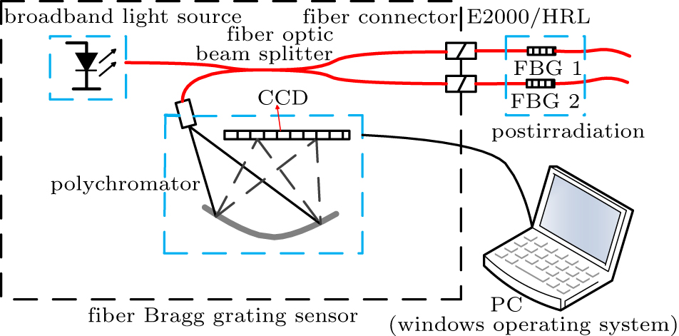
A sketch of the experimental setup is shown in Fig.
The main sources of measurement uncertainty are the magnitude of the change of the light absorption before and after irradiation, ΔA, and the ambient temperature T. The sum of squared uncertainties is multiplied by the dose response conversion factor K (= 8.33) to obtain the total uncertainty of the measurement. The K-type thermocouple temperature measurement accuracy is ±0.5 K, and the absorbance accuracy A is 0.001; the dose uncertainty can be calculated using the following equation:
 |
 |
Table
| Table 2.
Absorbed dose error. . |
Tables
 | Fig. 3. (color online) Reflective spectrum variation of the 825-nm optical Bragg grating pre-radiation and post-radiation. |
 | Fig. 4. (color online) Reflective spectrum variation of the 835-nm optical fiber pre-radiation and post-radiation. |
| Table 3.
825-nm Bragg grating wavelength variation with respect to radiation dose. . |
| Table 4.
835-nm Bragg grating wavelength variation with respect to radiation dose. . |
| Table 5.
825-nm Bragg grating FWHM and relative intensity variation with respect to radiation dose. . |
| Table 6.
835-nm Bragg grating FWHM and relative intensity variation with respect to radiation dose. . |
According to the experimental results, the difference between the peak wavelength of fiber Bragg grating before and after radiation could be obtained at different radiation doses.
The measurement accuracy of the peak wavelength of the Bragg grating reflection was 0.1 pm. Because the ambient temperature influenced the peak wavelength of the reflection, in the data-processing operation, the peak wavelength was converted into the corresponding wavelength at 20 °C. The thermocouple temperature measurement accuracy was 0.5 K. The conversion equation is
 |
 |
 |
From Eq. (
 |
The variation of the refractive index of the fiber Bragg grating at different doses is shown in Tables
| Table 7.
825-nm Bragg grating refractive-index variation with respect to radiation dose. . |
| Table 8.
835-nm Bragg grating refractive-index variation with respect to radiation dose. . |
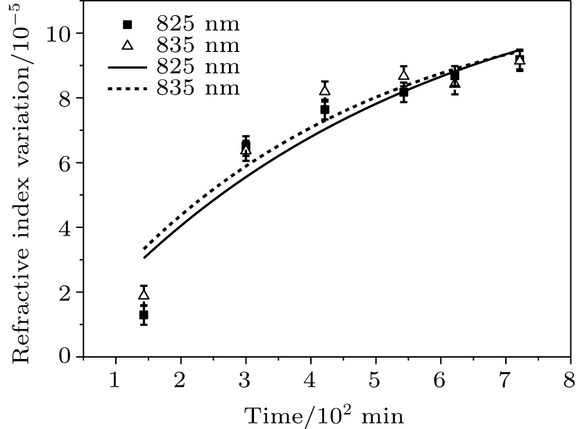
After radiation (Rd = 0 at this time), the peak wavelength of the grating reflection had a recovery or annealing effect (color-center annihilation); thus, ka can be obtained by fitting the recovery-effect curve. Then, we can obtain the particular parameters in Eq. (
After ionizing radiation at 1.0 × 10⁶ rad, the two fiber Bragg gratings were placed at room temperature, and their refractive-index variation with time was measured. The experimental results are shown in Tables
| Table 9.
825-nm Bragg grating recovery effect. . |
| Table 10.
835-nm Bragg grating recovery effect. . |
The color center created by the radiation is unstable and will gradually be annihilated. According to Eq. (
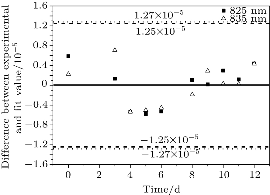
To evaluate the reliability of the recovery curves, the error of the fitted curve and the experimental data points were determined.
 |
 |
 |
 |
From Fig.
According to the color-center annihilation mechanism, the refractive index recovers in each irradiation interval. Therefore, the refractive-index variations were corrected according to the fitted annihilation rate. Owing to the time interval between the placement in the irradiation chamber and the start time of the measurement, the correction time of the grating has an uncertainty of 10 min, which yields a refractive-index variation of 3.0 × 10⁻⁸. Tables
| Table 11.
Corrected 825-nm Bragg grating refractive-index variation with respect to radiation dose. . |
| Table 12.
Corrected 835-nm Bragg grating refractive-index variation with radiation dose. . |
According to ka from the annealing experiment and the fitted curve in Fig.
 |
 |
From Eqs. (
The relationships between the refractive-index variation for Bragg wavelengths of 825 and 835 nm and the radiation time and dose rate are as follows:
 |
 |
According to the refractive-index variation and damage recovery, the 825- and 835-nm fiber grating color-center creation rates were kc_825 = κc_825Rd = 1.3 × 10⁻⁶Rd and kc_835 = κc_835Rd = 1.7 × 10⁻⁶Rd, respectively, and the annihilation rates were ka_825 = 3.8 × 10⁻⁵ min−1 and ka_825 = 3.4 × 10⁻⁵ min−1, respectively. Therefore, the average color-center creation rate was
 |
 |
 |
With Eq. (
 |
In low Earth orbit, the dose rate is 
 |
According to Eq. (
In Earth synchronous orbit, the dose rate is Rd2 = 5.2 × 10⁵ rad/year = 9.9 × 10⁻¹ rad/min. Then, the temperature drift due to radiation is
 |
According to Eq. (
We built a model of color-center creation by ionizing radiation with annihilation to study the shift and recovery of the refractive index of fiber Bragg gratings made of silica under and after 60Co γ radiation. By fitting the experimental data of the refractive-index shift, we obtained the model parameters. The effect of the radiation on the performance of the silica fiber Bragg gratings can thus be quantitively predicted for applications, e.g., temperature measurement in low Earth orbit and Earth synchronous orbit. The deviation of the refractive index of the grating in a known radiation environment can be regarded as a systematic error. This makes it possible to apply the silica fiber Bragg gratings as sensors in high-energy radiation environments, e.g., in space and nuclear facilities. However, the model provides a mechanism for the creation and annihilation of color centers, which elucidates the effect of radiation on the silica fiber Bragg gratings.
| [1] | |
| [2] | |
| [3] | |
| [4] | |
| [5] | |
| [6] | |
| [7] | |
| [8] | |
| [9] | |
| [10] | |
| [11] | |
| [12] | |
| [13] | |
| [14] | |
| [15] | |
| [16] | |
| [17] | |
| [18] | |
| [19] | |
| [20] | |
| [21] | |
| [22] |


