Zhang Xue, Meng Xiangfeng, Wang Yurong, Yang Xiulun, Yin Yongkai. Multiple-image encryption by two-step phase-shifting interferometry and spatial multiplexing of smooth compressed signal
. Chinese Physics B, 2018, 27(7): 074205
Permissions
Multiple-image encryption by two-step phase-shifting interferometry and spatial multiplexing of smooth compressed signal
Zhang Xue, Meng Xiangfeng †, Wang Yurong, Yang Xiulun, Yin Yongkai
Department of Optics, School of Information Science and Engineering, and Shandong Provincial Key Laboratory of Laser Technology and Application, Shandong University, Jinan 250100, China
† Corresponding author. E-mail: xfmeng@sdu.edu.cn
Project supported by the National Natural Science Foundation of China (Grant Nos. 61775121, 61307003, 61405122, and 11574311), Key R&D Program of Shandong Province, China (Grant No. 2018GGX101002), the Natural Science Foundation of Shandong Province, China (Grant No. R2016FM03), and the Fundamental Research Funds of Shandong University, China (Grant No. 2015GN031).
Abstract
A multiple-image encryption method based on two-step phase-shifting interferometry (PSI) and spatial multiplexing of a smooth compressed signal is proposed. In the encoding and encryption process, with the help of four index matrices to store original pixel positions, all the pixels of four secret images are firstly reordered in an ascending order; then, the four reordered images are transformed by five-order Haar wavelet transform and performed sparseness operation. After Arnold transform and pixels sampling operation, one combined image can be grouped with the aid of compressive sensing (CS) and spatial multiplexing techniques. Finally, putting the combined image at the input plane of the PSI encryption scheme, only two interferograms ciphertexts can be obtained. During the decoding and decryption, utilizing all the secret key groups and index matrices keys, all the original secret images can be successfully decrypted by a wave-front retrieval algorithm of two-step PSI, spatial de-multiplexing, inverse Arnold transform, inverse discrete wavelet transform, and pixels reordering operation.
Information transmission and storage, especially in the age of the internet, is an inevitable part of people’s lives. Meanwhile, an information security technique has emerged to prevent the unauthorized information usurpation. Since Réfrégier and Javidi proposed the double random phase encoding (DRPE) technique in 1995,[1] optical information security techniques have attracted an increasing number of researchers, because of their advantages such as high processing speed, high degree of parallelism, high encryption dimension, fast convolution, correlation operation, etc. Subsequently, some typical optical information processing techniques or transforms,[2] such as fractional Fourier transform,[3,4] digital holography,[5–7] phase retrieval,[8–10] two-beam interference,[11] fractional Mellin transform,[12] gyrator transform,[13] joint transform correlator,[14] jigsaw transform,[15] aperture movement,[16,17] and ghost imaging,[18–22] have been combined with DRPE to build more versatile security cryptosystems.
In 2000, Tajahuerce et al. proposed an optical encryption method of 3D information by DRPE and four-step phase-shifting interferometry (PSI),[23] in which the 3D object information was encrypted with the Fresnel diffraction pattern generated by DRPE, and then electronically recorded by four-step phase-shifting interferometry. Subsequently, three-step PSI was applied to a digital image encryption and watermarking method,[24] in which the secret image encoded by DRPE and Fresnel diffraction can be recorded into three interferograms. To raise the efficiency of encrypted information transmission, we proposed a two-step phase-shifting algorithm in 2006 and then applied it to image encryption,[25] by which an original object complex field can be recorded and reconstructed with only two interferograms.
Compressive sensing (CS) is a newly developed sampling-reconstruction technique that can complete the sampling and compressing simultaneously. This method can reduce the sampling rate, but at the expense of a complex reconstruction on the recipient.[26–30] Because of this unique advantage, CS has been successfully applied to optical information security fields. In 2014, Zhou et al. proposed an image compression-encryption hybrid algorithm with high security based on a key-controlled measurement matrix in CS,[31] in which the circulant matrix was utilized to construct the measurement matrix in CS and control the original row vector of the circulant matrix with a chaos system. Recently, CS has been introduced into the image encryption methods based on DRPE and PSI by Li et al.[32,33]
Besides the optical image encryption methods mentioned above, some pioneers have proposed multiple-image encryption methods based on wavelength multiplexing,[34] position multiplexing,[35] phase-only mask (POM) multiplexing,[36,37] lateral shifting,[38] etc. In 2014, Deepan et al. proposed a multiple-image encryption scheme by spatial multiplexing based on CS and the DRPE,[39] in which a space multiplexing concept was used to exploit the redundant space available due to the compressive sensing process. In 2016, Sui et al. proposed a multiple-image encryption method based on the chaotic structured phase masks under the illumination of a vortex beam in the gyrator domain,[40] in which two structured phase masks were utilized to reconstruct the phase keys by nonlinear iterative phase retrieval algorithm. Based on the modified logistic map algorithm,[41,42] compressive ghost imaging and CS, we recently proposed a multiple-image encryption method,[43] in which after a random phase-only-mask generation[44] by the modified logistic map algorithms, the ciphertext can be acquired by discrete cosine transformation, random sampling and scrambling, the combined image generation, and compressive ghost imaging. At this time, we propose a multiple-image encryption method based on two-step phase-shifting interferometry and spatial multiplexing of smooth compressed signal, aiming to reduce the phase-shifting steps and the data volume of the secret images for n images encryption program, and further enhance the data usage efficiency of interferograms derived from two-step phase-shifting interferometry. The principle and procedure will be described firstly, and then a set of simulations will be given to verify the feasibility and robustness of the scheme, finally a conclusion will be drawn.
2. Analysis of fundamental principles
2.1. Brief introduction to compressive sensing
In a conventional sampling process, a massive amount of data collected can only be largely discarded at the compression stage to facilitate storage and transmission. This process of massive data acquisition followed by compression is extremely wasteful.[27] The compressive sensing (CS) theory, which combines sampling and compression into a single non-adaptive linear measurement process, can recover certain signals and images from far fewer samples than the Shannon–Nyquist sampling theorem requires, and CS consists of three steps: sparse representation, random projection, and reconstruction.[26–28]
In signal compression theory, any signal that is sparse or sparsifiable can be compressed through a measurement matrix. Taking an N × N real value matrix X as an example, it represents a natural image containing a small amount of zero values in the time domain. However, it can be sparsely represented in some arbitrary orthonormal basis Ψ = [ψ1, ψ2, …, ψn] by discrete cosine transformation (DCT) or discrete wavelet transformation (DWT),[45] which can be expressed as[26–28]
where α is an N × N coefficient matrix of X projected on the Ψ domain, and Ψ is a normal orthonormal basis with ψi as columns. After setting α that is less than the preselected threshold as zero, a K-sparse signal α′ with K non-zero values can be obtained. It is the K-sparse signal that should be the basic requirement for the CS theorem. The projection coefficient α′ offers a concise summary: most of the coefficients are small, and relatively few large coefficients capture most of the information, i.e., the knowledge of K-sparse signal α′ is equivalent to the knowledge of X. Thus, we are able to reconstruct the image in the time domain, as long as we have a small amount of large projection coefficients in the Ψ domain, which enables CS to reconstruct a general image from the K-sparse signal α′.
Besides the random measurement matrix Φ, a sensor satisfied restricted isometry property (RIP) with size M × N, such as a Gaussian or Hadamard matrix, will exhibit a very low coherence with any sparsifying operator. It is worth mentioning here that a prerequisite should be satisfied first for Φ prior to compressing the image[26–28]
where C is a small positive constant, and k is the maximum number of non-zero elements in each column of the K-sparse signal after the Arnold transform in order to make the non-zero distribution in each column uniform. The linear measurement process can be expressed as
where Y stands for the measurement data with size M × N. If Φ holds RIP, a steady solution can be obtained from the above underdetermined system by l1-norm minimization
where ‖ · ‖1 denotes the l1-norm, and is the solution to the convex optimization program. Besides the l1-norm minimization,[46] other methods, such as orthogonal match pursuit (OMP),[47] basic pursuit (BP),[48] subspace pursuit (SP),[49] etc., are able to reconstruct the sparse solutions as well. After obtaining the estimated coefficients , then through the inverse Arnold transform and inverse basis transform (e.g., inverse DWT or inverse DCT), a recovered image without perceptual loss but data reduction will show up.
2.2. Image compression and encryption
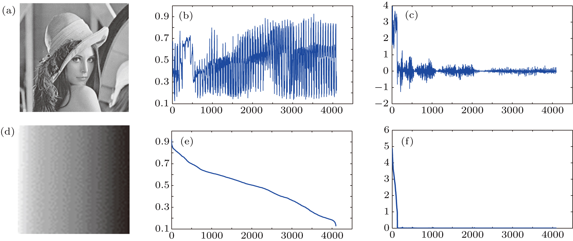
The decay of Fourier or wavelet coefficients of smooth signals exhibits a power law, which means that for the same image, the reordered smooth image performs with a stronger sparse property than the original image in the Fourier or wavelet domain.[50] Inspired by this thought, prior to compression, we reorder the pixels in ascending/descending order to lower the inherent frequency of the original image. For a further step, the simulated results are also presented and listed in Fig. 1. Here, we set the Haar wavelet basis as the normal orthonormal basis Ψ. It is evident that the wavelet coefficients of the reordered smooth image decay faster than the original image, which implies that we will reconstruct higher fidelity images with fewer measurements.
Fig. 1. (color online) (a) Original ‘Lena’ with 64 × 64 pixels; (b) pixels distribution of (a); (c) the wavelet coefficients distribution of (a) after five-order Haar DWT; (d) the reordered smooth image in descending order of (a); (e) pixels distribution of (d); (f) the wavelet coefficients distribution of (d) after five-order Haar DWT.
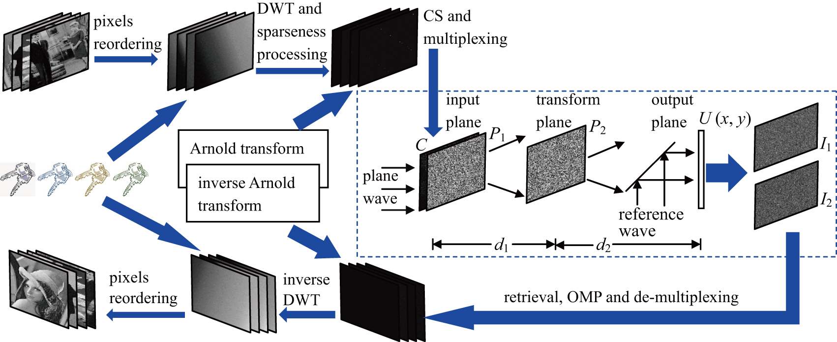
For simplicity, as depicted in the encryption part shown in Fig. 2, taking four secret images for instance, all the pixels of each image are reordered in ascending order, and four relative index matrices recoding every pixel’s original location can be simply represented as SK1, SK2, SK3, and SK4, followed by five-order Haar wavelet transform and sparseness operation, i.e., any element less than the preset threshold is set as zero. Then, Arnold transform and sample operation could be implemented as Eq. (3), where M = N / 4. According to spatial multiplexing, a combined image C with the size of N × N, consisting four M × N sample results: Y1, Y2, Y3, and Y4 from top to bottom, can be grouped, which will be located at the input plane of the two-step PSI encryption system, and then encoded into two interferograms ciphertexts.
Fig. 2. (color online) Schematic diagram of the multiple image encryption and decryption process.
In the two-step PSI encryption system shown in Fig. 2, a linearly polarized light is collimated, and then divided into two arms (object wave arm, and reference wave arm) by the beam splitter (BS). On the object wave arm, both the combined image C(x1, y1) and the first random phase mask (RPM) P1 are located at the input plane, while the second RPM P2 is located at the transform plane. The distances between the input plane and the transform plane, and between the transform plane and the output plane are denoted by d1 and d2, respectively. When the object wave with wave length λ illuminates the combined image C, at the output plane, a complex wave field can be mathematically represented as[24,25]
where FrTd stands for the Fresnel transform of distance d, while P1(x1, y1) and P2(x2, y2) are two independent white noises uniformly distributed in [0,1].
On the reference wave arm, the phase δ of the reference wave is monitored by a piezoelectric transducer mirror (PZT). After interfering with the object wave at the CCD plane, two interferograms will be obtained by the two-step PSI algorithm[25]
where A0(x, y) and φ(x, y) are amplitude and phase of U (x, y), respectively. Ar, the constant amplitude of the on-axis reference plane wave, is larger than the maximum of A0(x, y). Therefore, the combined image C has been encoded into two interferograms ciphertexts. Afterwards, four secret key groups SGi consisting of each index matrix SKi and RPM: P2 will be distributed to four different users: Useri (i = 1, 2, 3, 4). All the ciphertexts and secret keys except four secret key groups are kept by the cryptosystem, anyone who would like to get the decrypted image has to go to the cryptosystem with his/her own secret key group (example: SG1 consists of SK1 and P2).
2.3. Image reconstruction and decryption
The decryption process will occur when the Useri enters the cryptosystem with his/her secret key group SGi. As the decryption part illustrates in Fig. 2, after the two interferograms ciphertexts I1 and I2 are loaded into the decryption system, the reconstructed complex wave field U′ can be mathematically expressed as[25]
where
In case the Useri has the complex information and with the help of RPM P2 in the secret key group SGi, the recovered combined image C′ at the input plane will be reconstructed with corresponding auxiliary keys
where abs and IFrT denote the real amplitude extraction operation and inverse Fresnel transform, respectively.
It is not until the authorized Useri is able to get the exclusive module Yi (i = 1, 2, 3, 4) consisting in C′ from top to bottom that he/she can obtain correct decrypted images through the next decryption work. After the OMP reconstruction algorithm and inverse Arnold transform, four K-sparse images are recovered; then taking the inverse DWT operator followed by reordering in the index matrix ( SK1, SK2, SK3, and SK4) order, all the original secret images can be decrypted.
Correlation coefficient (CC),[51,52] normalized cross correlation (NCC),[53] structural similarity index metric (SSIM), and mean square error (MSE) are adopted as objective criterions to evaluate the image quality between the recovered and the original secret image.
3. Simulations
A series of simulations have been carried out using MATLAB R2014a to verify the feasibility and validity of the proposed method. All resolutions of the digital images are 15 μm, the parameters: λ = 532 nm, d1 = d2 = 0.01 m, and δ = π/2. The sizes of the measurement key and the sampled results are 64 × 256, and the sizes of other images are 256 × 256.
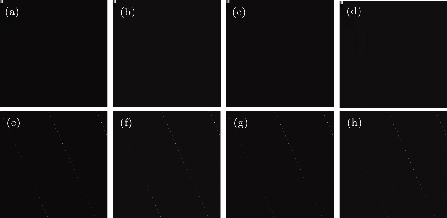
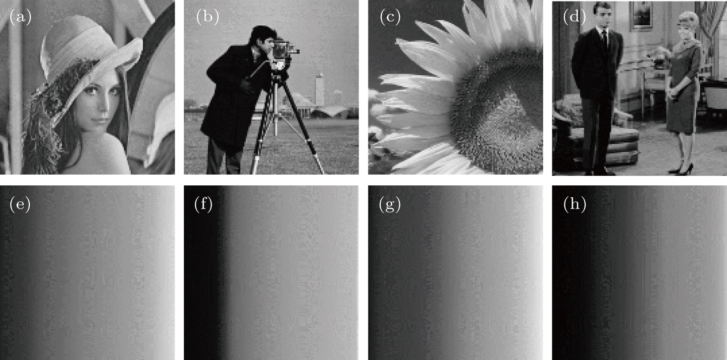
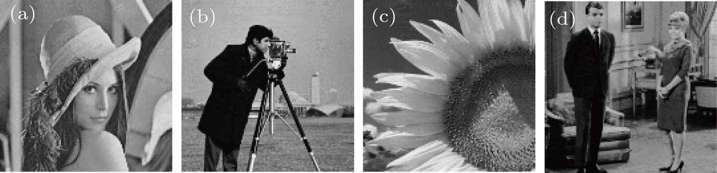
Four plaintext images with 256 × 256 pixels to be encrypted are shown in Figs. 3(a)–3(d), and the corresponding reordered images in ascending order are shown in Figs. 3(e)–3(h). After taking 5-order Haar DWT and making sparse operation, four sparsely represented figures are shown in Figs. 4(a)–4(d), and figures 4(e)–4(h) show the corresponding transformed images after Arnold.
Fig. 4. (a)–(d) Four sparse images after 5-order Haar DWT; (e)–(h) the corresponding images after Arnold transform for (a)–(d).
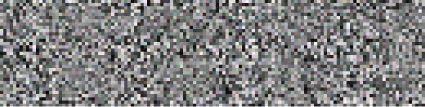
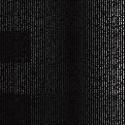
A preselected Gaussian random matrix, acting as a measurement matrix, is shown in Fig. 5, and the four compressive images are displayed in Figs. 6(a)–6(d). The final combined image C as an input image in the encryption system is shown in Fig. 7. The two RPMs (P1 and P2) are shown in Figs. 8(a) and 8(b), respectively, while figures 9(a) and 9(b) depict the two interferograms (I1 and I2).
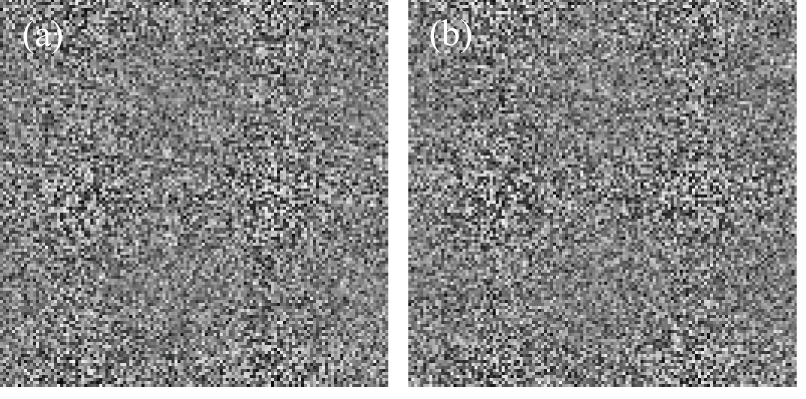
Fig. 9. Two interferograms ciphertexts: (a) I1, (b) I2.
During decryption, figures 10(a)–10(d) show the four decrypted images with all the corrected keys, and the corresponding CCs, NCCs, MSEs, and SSIMs are listed in Table 1. Obviously, these final decrypted images of good quality are very similar to the corresponding individual secret images.
Fig. 10. (a)–(d) Four decrypted images by all the correct keys.
Table 1.
Table 1.
Table 1.
Four quality evaluation metrics for the decrypted images.
.
Lena
Cameraman
Flower
Couple
CC
0.9983
0.9989
0.9985
0.9981
NCC
0.9991
0.9992
0.9990
0.9987
SSIM
0.9851
0.9816
0.9851
0.9752
MSE
4.2×10⁻⁵
4.9×10⁻⁵
5.2×10⁻⁵
8.7×10⁻⁵
Table 1.
Four quality evaluation metrics for the decrypted images.
.
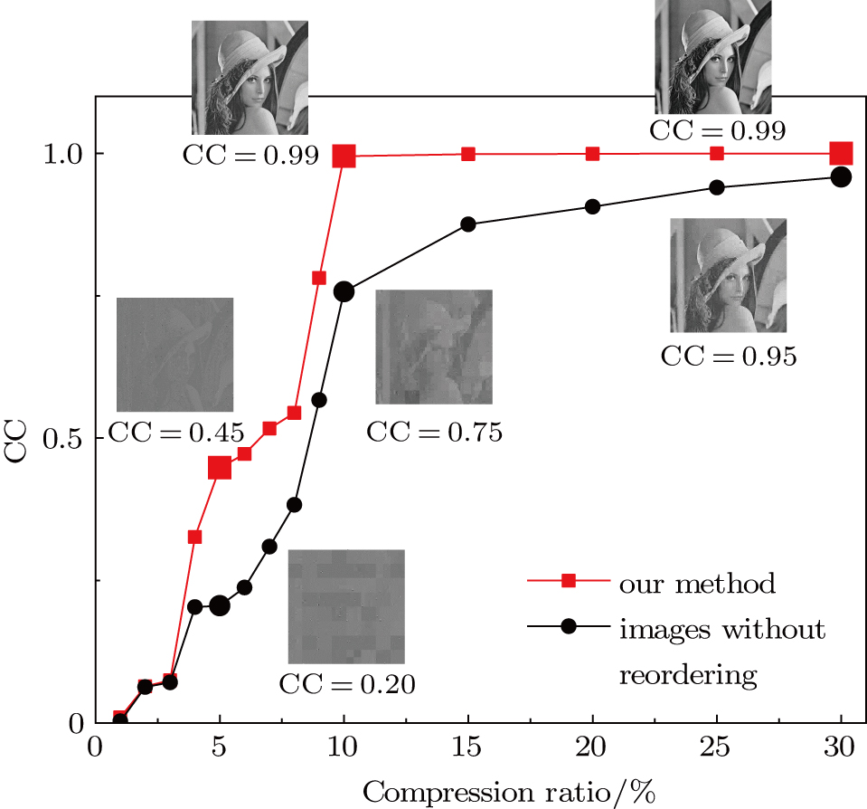
Next, as shown in Fig. 11, we take ‘Lena’ for instance and compare the encryption performance of our method with the method without reordering in prior to compression. Six large points denote six different reconstructed images under respective compression ratios. The three images above the red curve are recovered by our method. Obviously, our method performs better under the same compression ratio (M / N), and it is not until the compression ratio is less than 10% that CC is less than 0.9, which implies that our method is capable of encoding more than 10 images with the perfectly recovered image quality. However, image quality recovering without reordering falls seriously with the reduction of the compression ratio. Therefore, our method sharply improves data usage efficiency and lessens the storage space.
Fig. 11. (color online) The variation curve between the CCs of the decrypted image and compression ratio.
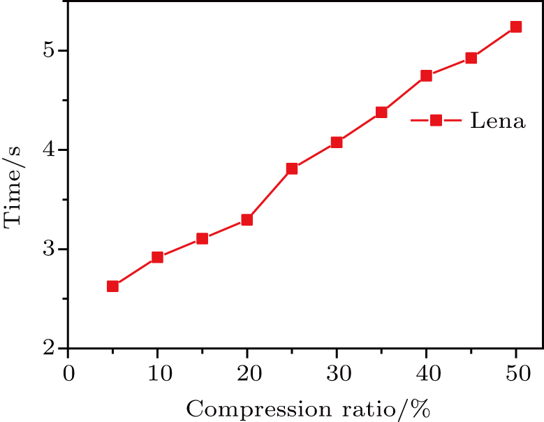
Taking ‘Lena’ as an example, the time complexity of the proposed encryption method is plotted in Fig. 12, where the row coordinate denotes the compression ratio, while the column coordinate is the total time cost of encryption and decryption for ‘Lena’ (Intel(R) Core(TM) i5-4590CPU @ 3.30 GHz; RAM: 8.00GB; No GPU). From the results, we can see that the time cost of our method accelerates linearly with the growth of the compression ratio. Because a high fidelity image with CC greater than 0.9 is going to be decrypted when the compression ratio is larger than 10%, a ‘Lena’ can be encrypted and decrypted for only 3 seconds using our method, and the time complexity of other different original images performs the similar result as Fig. 12.
Fig. 12. (color online) The variation curve between the time for encryption and decryption and the compression ratio.
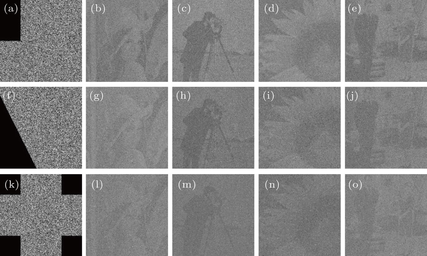
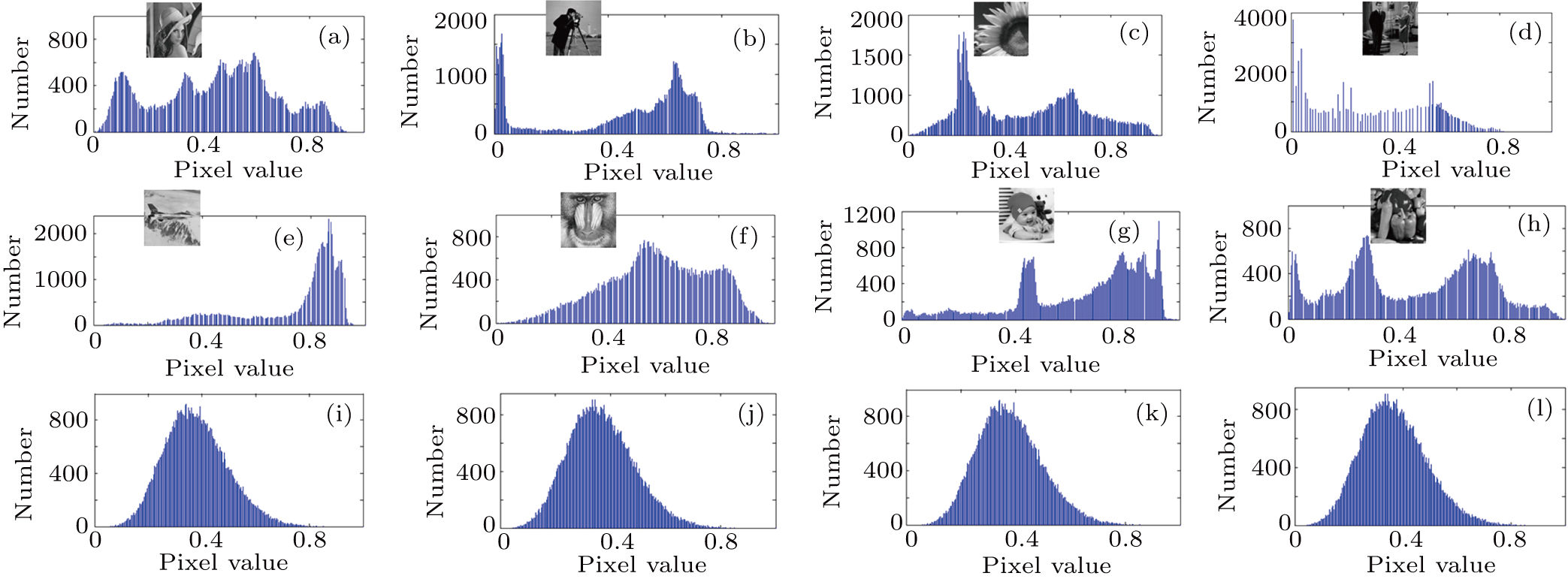
To reveal that our proposed method is resistant to statistical attack,[54–57] we encrypt two sets of plain images, each of which consists of four images. Fig. 13 shows the histograms of original images and interferograms, where original images have obvious characteristics and differ from each other seriously, but the distribution of each interferogram is quite similar and obeys the Gaussian distribution. Besides, for different sets of images, the distributions of interferograms remain, which implies that the image encryption performance of the proposed method is good enough.
Fig. 13. (color online) Two sets of histograms of original images and interferograms. Set1: (a)–(d) original images; (i)–(j) two interferograms I1 and I2; Set2: (e)–(h) original images; (k)–(l) two interferograms I1 and I2.
To further illustrate the performance, the correlation of adjacent pixels is analyzed. We randomly select adjacent pixels from original images and interferograms on the horizontal (vertical, diagonal) direction, and calculate the adjacent pixels correlation.[54–57] All results are shown in Table 2, from which we can see that the adjacent pixels correlation of original images is high, close to 1.0, while the adjacent pixels correlation of interferograms is low, close to 0, which means that the pixels scrambling of our proposed method works very well.
Table 2.
Table 2.
Table 2.
Adjacent pixels correlation of original images and interferograms.
.
Horizontal
Vertical
Diagonal
Lena
0.9222
0.9603
0.9030
Cameraman
0.9368
0.9585
0.9082
Flower
0.9376
0.9263
0.9050
Couple
0.9530
0.9654
0.9283
I1
0.0043
0.0145
0.0005
I2
0.0020
0.0087
0.0029
Table 2.
Adjacent pixels correlation of original images and interferograms.
.
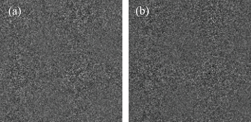
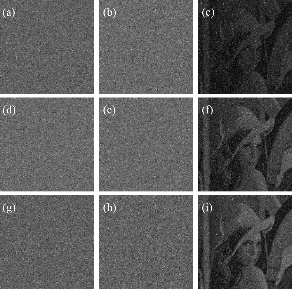
Then, a set of robustness tests against possible attacks are investigated. Two interferograms are contaminated by three different noise attacks: Gaussian white noise of mean 0 and variance 0.01 (as shown in Figs. 14(a) and 14(b)), salt and pepper noise of density 0.01 (as shown in Figs. 14(d) and 14(e)), speckle noise of mean 0 and variance 0.01 (as shown in Figs. 14(g) and 14(h)), and the corresponding reconstructed images for the ‘Lena’ image are shown in Figs. 14(c), 14(f), and 14(i). From these pictures we can see that all the retrieved images can be recognized without doubt.
Fig. 14. (a) and (b) Two interferograms distorted by Gaussian white noise; (c) the retrieved image by (a) and (b); (d) and (e) two interferograms distorted by salt and pepper noise; (f) the retrieved image by (d) and (e); (g) and (h) two interferograms distorted by speckle noise; (i) the retrieved image by (g) and (h).
The cropping attack on P2 is tested here. Figure 15 shows three different cropping ways and their decrypted images. From the results, we can see that with the rise of cropping ratio, the fidelity or visibility of decrypted images is declining. But we can still distinguish our interested part from the results when P2 suffers from the cropping attack ratio. Therefore, our proposed method is capable of resisting the cropping attack.
Fig. 15. Three different types of cropping attack: (a) 12.5% occlusion; (f) 20% occlusion; (k) 25% occlusion; the corresponding decrypted images follow with them at the same rows.
Different from our previous encryption works based on two-steps of phase-shifting interferometry,[25] in this paper, we introduce an advanced image acquisition and reconstruction technique termed compressive sensing theorem and encrypt n images with only two interferograms. The proposed method can enhance the data usage efficiency of interferograms and lessen the storage of ciphertexts. Compared with the reported optical cryptosystems based on compressive sensing and DRPE,[39] the main advantage of our proposed scheme can be summarized as follows. (i) Prior to compression, we first reorder the original images, which results in smaller non-zeros wavelet coefficients of original images and a lower compression ratio with higher decrypted quality. (ii) The two-step phase-shifting interferometry is easily capable of recording the phase information of complex amplitude which is difficult for DRPE.
4. Conclusion
In conclusion, we proposed a multiple-image encryption method based on two-step phase-shifting interferometry and spatial multiplexing of the smooth compressed signal. Followed by pixels ascending reordering, DWT, sparseness operation, Arnold transform and pixels sampling for four different secret images, one combined image can be grouped with the aid of CS and spatial multiplexing techniques. Then the combined image can be encoded into only two interferograms ciphertexts by the two-step PSI and DRPE, by which the efficiency of ciphertexts data transmission has been greatly raised. The use of the CS theory decreases the data volume of the secret images, thus, with this approach, it is possible to realize multiple image encoding and encryption. Both theoretical analysis and numerical simulations confirm the feasibility of the proposed method.


