Project supported by the National Natural Science Foundation of China (Grant Nos. 11474097, 11374099, and 11274116) and the Open Fund of the State Key Laboratory of High Field Laser Physics (Shanghai Institute of Optics and Fine Mechanics), China.
Project supported by the National Natural Science Foundation of China (Grant Nos. 11474097, 11374099, and 11274116) and the Open Fund of the State Key Laboratory of High Field Laser Physics (Shanghai Institute of Optics and Fine Mechanics), China.
† Corresponding author. E-mail:
Project supported by the National Natural Science Foundation of China (Grant Nos. 11474097, 11374099, and 11274116) and the Open Fund of the State Key Laboratory of High Field Laser Physics (Shanghai Institute of Optics and Fine Mechanics), China.
This paper reports the plasmonic lasing of a split ring filled with gain material in water. The lasing mode (1500 nm) is far from the pump mode (980 nm), which can depress the detection noise from the pump light. The laser intensities of the two modes simultaneously increase by more than 103 in amplitude, which can intensify the absorption efficiency of the pumping light and enhance the plasmonic lasing. The plasmonic lasing is a sensitive sensor. When a single protein nanoparticle (n = 1.5, r = 1.25 nm) is trapped in the gap of the split ring, the lasing spectrum moves by 0.031 nm, which is much larger than the detection limit of 10−5 nm. Moreover, the lasing intensity is also very sensitive to the trapped nanoparticle. It reduces to less than 1/600 when a protein nanoparticle (n = 1.5, r = 1.25 nm) is trapped in the gap.
Molecular information in biochemistry and biomedicine can be obtained by single molecular detection.[1] Especially, label-free detection of single molecules (e.g., viruses, proteins) allows the object to be detected in the native state in real time.[1–6] Recently, surface-enhanced Raman scattering,[1] optical microcavities,[2] optical trapping in nanoholes,[3] etc. were studied for the detection of unlabeled proteins. Plasmonic resonance enhancement plays a key role in the detection of single molecules. Dantham et al. reported the detection of a single thyroid cancer marker and bovine serum albumin proteins using a plasmonic–photonic hybrid microcavity.[4] Baaske et al. studied the interaction between a single molecule and nucleic acid with a label-free microcavity biosensor platform.[5] The detection limit of the resonance wavelength shift of the plasmonic nanostructure is usually of 10−5 nm.[4] However, the resonance peaks are usually 10–100 nm wide and the noise is very large.
Split-ring resonators (SRRs) are highly tunable nanostructures supporting multipolar resonance[7] and they have large near-field enhancements in the gap, which both lead to the potential of practical applications in localized surface plasmon resonance spectroscopy and sensing.[8–12] Cubukcu et al. reported an SRR sensor for infrared detection of monolayer of octadecanol molecules. The large near-field enhancements in the gap were caused by the resonant coupling of the molecular infrared vibrational modes overlapping the plasmonic resonances.[8] Yue et al. demonstrated the detection of rhodamine 6G molecules by Raman scattering using gold SRRs as substrates.[9]
Surface plasmon polaritons (SPPs) are highly sensitive to changes in the surrounding medium[1,13–20], and form the basis for surface plasmon resonance sensing, such as the refractive index fluctuation induced by surface biomolecular binding. However, plasmonic nanostructures are mostly made of metallic components, which unavoidably suffer from high dissipative losses. The related low-quality factor undoubtedly restricts their applications in sensing or switching.
Plasmonic lasing is a new class of coherent amplifier with size well below the diffraction limit.[21–24] Researchers have paid a great deal of attention to reducing the threshold, achieving large Purcell enhancement, realizing broadband tunability, acquiring more lasing modes, and so on.[25–28] The intense, coherent light and strong mode confinement significantly enhance the light–matter interactions, which makes plasmonic lasing have possible applications ranging from sensing to imaging and information technology.[22–24] Recently, Ma et al. demonstrated explosives detection by monitoring the change of the lasing intensity. The limit to detect explosives in air under normal conditions was as high as sub-part-per-billion.[29]
In this paper, we study plasmonic lasing and its application in single-molecular detection. The lasing is based on the multipolar resonances in split-ring resonator (SRR) nanostructures filled with gain material. The lasing spectrum greatly changes when a nanoparticle is trapped in the split-ring gap. We further study the sensitivity of the plasmonic lasing to the refractive index, size and number of the trapped nanoparticles.
Figure
The refractive index of the gain medium is ε = n + ik, here n is the real part and the imaginary part k describes the absorption of the incident light or the amplification coefficient of the lasing intensity.[25,28,31] Plasmonic lasers have been successively realized in a series of gain materials, such as quantum dots, dye molecules and rare earth ions.[21,23,32] Gain material co-doped with Yb3+: Er3+ is chosen as an example of spaser used to detect single molecules. The absorption band of Yb3+ ions is at 950–990 nm and the broadband luminescence of Er3+ ions is in the range of 1480–1600 nm.[33,34]
The finite-element method (COMSOL) is used to study the optical properties of the SRR filled with gain medium. The nanostructures are closed by a spherical perfectly matched layer. During the numerical simulation, the maximum element size of local adaptive mesh refinement is 20 nm and the minimum is 0.2 nm. The minimum step is set as 1 × 10⁸ Hz in the numerical calculation of the scattering and absorption spectra.
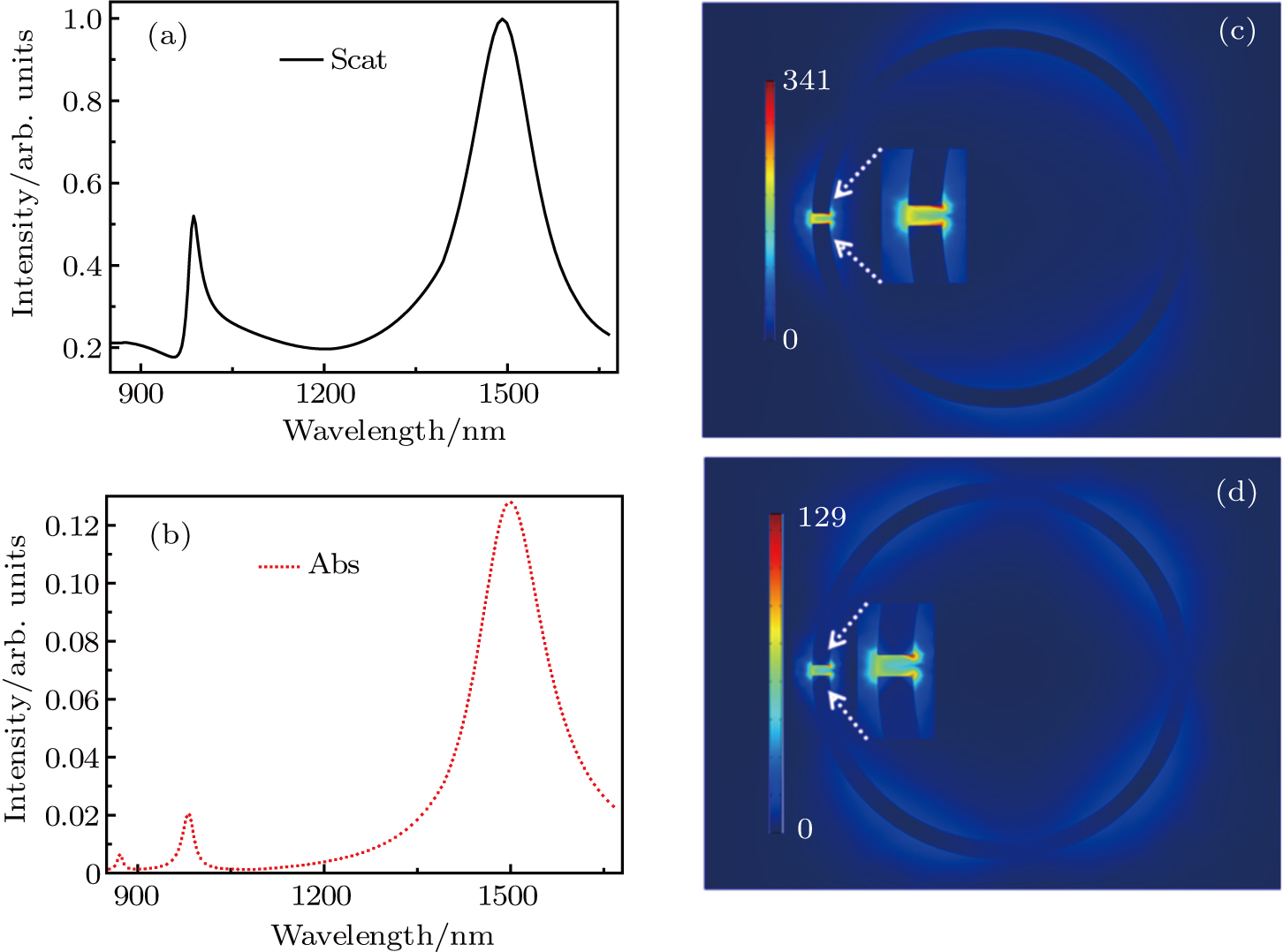
Figure
The emission cross-section of rare earth ions is usually small, but it is still strong enough to support a plasmonic laser. Molina et al. demonstrated a Nd3+-based laser by means of localized surface plasmon resonances supported by chains of metallic nanoparticles.[32] When the pump laser polarization was perpendicular to the chains, the quality factor was less than the value in our theoretical model.[14,23] The experimental results indicated that the plasmon laser was rather bright when the pump laser power was larger than 225 mW.[32] Nanoparticles co-doped with Yb3+:Er3+ and glasses have been demonstrated to be the most efficient emitting rare earth ions. Therefore, the gain is strong enough to generate a plasmonic laser in this system. Moreover, the gain material co-doped with Yb3+: Er3+ is just one example of a plasmonic laser used to detect single molecules.
Figures
We also study the plasmonic properties of a ring resonator with the same parameters of the SRR except for the gap. When the wave vector of the incident light is perpendicular to the ring, the dipole resonance is excited, but the maximum electric field only enhances up to 56 times, which is much less than that of the SRR. For the oblique incident light, the multipolar resonances of a single ring can be excited, but they do not overlap in spatial distribution which hinders the simultaneous enhancements of the pump light and plasmonic lasing. Obviously, the SRR is a better choice to generate plasmonic lasing.
Figure
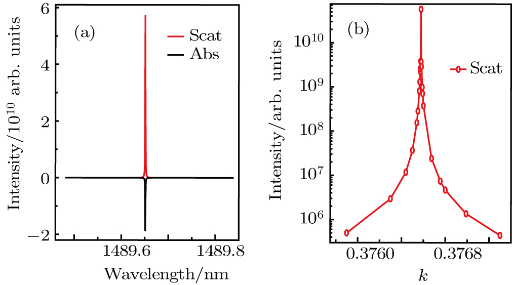 | Fig. 3. (color online) (a) The scattering and absorption spectra for the gain coefficient k = 0.376577. (b) The dependence of the scattering intensity on k. |
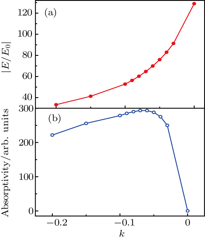
In the gain medium, because of a large absorption cross-section at 980 nm and a long excited-state lifetime, the Yb3+ ions efficiently absorb energy from the pump light and transfer the energy to the Er3+ ions. Electrons in the Er3+ ions damp to the ground state from the 4I13/2 state, [33,34] and transfer the energy to the plasmon at the lasing wavelength by resonant coupled transition. However, the pump light is at the hexapolar resonance mode. Besides the pump light energy, the Yb3+ ions can also absorb resonant energy from the hexapolar plasmon. Figure
High absorptivity of the gain medium is beneficial to obtain intense plasmonic lasing. The absorptivity is proportional to the extinction coefficient k and the pump light intensity. The pump light intensity in the SRR gap is proportional to the square of the LEFE. Hence the absorptivity of the gain medium is Abs∝ −k(E/E0)2. Figure
For biomolecular detection, SRR plasmonic lasing has two special benefits. First, the pump light is far away from the lasing light, which can depress the noise coming from the pump light. Second, the lasing light and the pumping light are greatly enhanced simultaneously, which can greatly decrease the threshold of the pumping light and further reduce noise. Most importantly, biomolecules avoid being damaged.
The scattering spectra of the SRR plasmonic lasing are very sensitive to the surrounding material, which can be used as ultra-sensitive sensors. To investigate the sensing performance, we study the scattering spectra of the SRR nanostructure when nanoparticles are trapped in the gap.
Recently, many works have focused on the detection of protein molecules or viruses. The refractive indices of different types of proteins slightly change in the range of 1.45–1.5.[37–39] In our model, we set the refractive index of the protein nanoparticle as 1.5. A monolayer protein is approximately 3-8 nm thick, which means the radius of the protein molecules is several nanometers as a sphere.[39,40] Apart from biological molecules, the detection of polymer or semiconductor nanoparticles attracts a lot of attention.[41,42] In this paper, we also study the cases of nanoparticles with refractive indices in the range of 1.7–3.
In SRR plasmonic lasing, the hot spot of the electric field is mainly located in the nanogap shown in Fig.
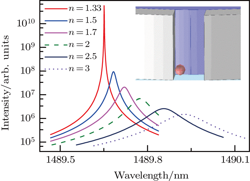 | Fig. 5. (color online) Scattering spectra for different nanoparticles trapped in the gap. Here the nanoparticle radius is kept at 1.25 nm. |
In order to avoid computation errors caused by re-meshing the geometry, we simply set the refraction index of the nanoparticle domain to be that of water in the case of no nanoparticle. The scattering intensity is as strong as 1010 and the FWHM is very narrow, only 0.01 nm. The peak of the lasing spectrum moves from 1489.652 nm to 1489.683 nm when a protein nanoparticle is attracted in the SRR gap, as shown in Fig.
The detection precision is equal to the spectrum shift divided by the FWHM of the plasmon resonance. Recently, people tried many methods to reduce the FWHM of the scattering spectra. For example, Fano resonance is an important way to enhance the spectral detection resolution.[43,44] In order to compare the detection precision of the SRR with or without a plasmonic laser, we study the scattering spectra of the SRR without gain material, which are shown in Fig.
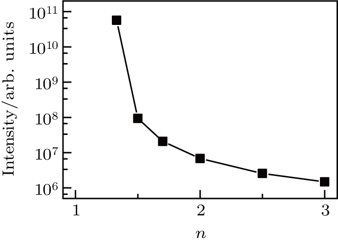
Ma et al. demonstrated that the lasing intensity was ultrasensitive to the adsorbed molecules. Figure
The detection of polymer (n = 1.7) or different semiconductor nanoparticles by the SRR plasmonic lasing is also studied. The scattering peak is redshifted due to hybridization of the split-ring plasmons.[43] The shift of the resonance wavelength prevents the resonant energy transferring from the gain medium to plasmon, leading to a weak intensity and wide FWHM of the scattering spectrum. However, the lasing intensity is still as large as 105 and the linewidth is only 0.135 nm for the nanoparticle with n = 3. Compared with the case of pure water, the lasing spectra move by 0.069, 0.123, 0.203 and 0.274 nm for the nanoparticle indexes n = 1.7, 2, 2.5 and 3, respectively. In each case, the shift of the lasing spectra is larger than its FWHM. Besides, the lasing intensities are 2.08 × 107,6.82 × 106,2.58 × 106, and 1.48 × 10⁶, respectively, which are lower than the value of pure water by 2 to 3 orders. Obviously, the SRR plasmonic lasing is a superior method for detecting single polymer or semiconductor nanoparticles.
As illustrated in Fig.
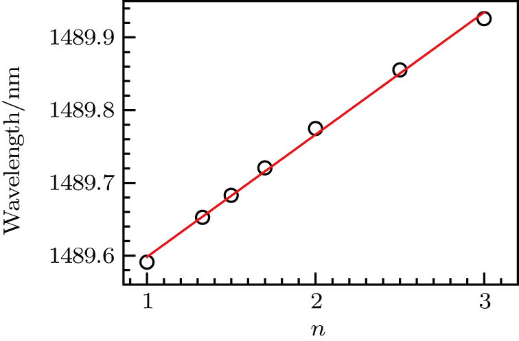 | Fig. 7. (color online) The peak wavelength as a function of the refractive index n of the trapped nanoparticle. The red line depicts the linear fit. |
Figure
 | Fig. 8. The resonance wavelength shift with varied numbers of protein nanoparticles. The inset shows the location of four nanoparticles. |
We note that the diameter of the trapped nanoparticle is 2.5 nm and the nanogap width is 6.0 nm. Therefore, four nanoparticles can be trapped in the four designed positions. This is feasible in theory, though the exact positions slightly fluctuate.
The gap of the three-dimensional (3D) nanocrescent is 6.0 nm, which can be fabricated by several methods, such as electron-beam lithography, photochemical deposition and self-assembly nanofabrication.[48–50] For example, Duan et al. have demonstrated nanoprism pairs of uniform sizes with systematic reduction of the gap to 0.5 nm and narrowing the bridge to 3.0 nm by using high-resolution electron-beam lithography.[48] Ahmed et al. have reported a single antenna with a feed gap of 6.0 nm fabricated by a top-down approach and demonstrated single-molecule enhanced Raman scattering by taking advantage of the high local field enhancement in the nanogap.[49] Moreover, Neubrech et al. proved that photochemical metal deposition onto lithographically fabricated nanoantenna can be used to decrease the gap between the nanoantenna dimers down to below 4.0 nm, which can realize new generation devices for ultrasensitive optical biosensing.[50]
The diameter of the trapped nanoparticle is 2.5 nm and the nanogap width is 6.0 nm. That is to say, the width of the gap is larger than the double diameters. Therefore, four nanoparticles can be trapped in the four designed positions. Recently, Chen et al. studied surface-enhanced Raman scattering via a plasmonic nanogap of 2 nm between two Ag nanoparticles, while the molecule was modeled as a sphere of radius 1 nm and located at the nanogap center.[51] Moreover, Arnold et al. predicted that the wavelength shift of whispering-gallery modes in microspheres by protein adsorption was proportional to the protein surface density.[46] Thus, the wavelength shift becomes larger with increased numbers of nanoparticles.
Detecting a smaller molecule with a more sensitive method is the main objective in the field of single-molecule detection. For example, Dantham et al. reported the detection of single bovine serum albumin protein with mass of only 0.11 ag.[4] This article theoretically provides a low-threshold, low-noise and high-intensity label-free single-molecule detection method. This method is based on spaser (surface plasmon amplification by stimulated emission of radiation), which can reduce damage to molecules and can be applied to the detection of living cells. For example, Galanzha et al. have demonstrated that a 22 nm spaser (plasmonic nanolaser) can be used as a super-bright, water-soluble, biocompatible probe, which can generate stimulated emission directly inside living cells and animal tissues.[52]
Figure
 | Fig. 9. (color online) The scattering spectra of a trapped nanoparticle with different sizes of (a) r = 1.0 nm and (b) r = 0.3 nm. |
Figure
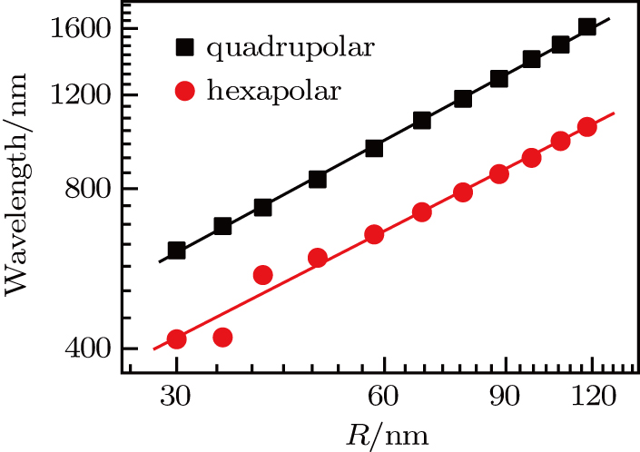
Broadband tunability is a critical driver for the practical application of plasmonic lasers. Recently, many plasmonic lasers with wavelengths from 489 nm to 1500 nm were demonstrated based on the gain materials of semiconductors (CdS, InGaAs, InGaN),[22, 24, 27] organic dye (OG-488),[23] rare earth ions (Nd3+),[32] dye molecules (IR-140),[53] and so on. Yang et al. achieved dynamic tuning of the plasmon lasing wavelength by modulating liquid gain materials with different refractive indices.[53] To demonstrate broadband tunability, we change the outer radius of the SRR and keep the other geometric parameters constant. The results are shown in Fig.
In view of the effect of the optical tweezers, we mainly study the nanoparticle trapped at a point with strong electric field in the SRR gap. However, in actual applications, the nanoparticle moves back and forth in the gap. Due to the localized surface plasmon resonance and lighting rod effect, the maximum electric field is located in the gap.[54,57] In order to further understand the influence of the trapped location, we study the spectra when the nanoparticle is trapped at different locations under the condition of plasmonic lasing. The middle inset shows four different locations of the nanoparticle (r = 1.25 nm) and they are labelled as 1 to 4, respectively. The left one is the electric field distribution on the middle surface and the right is that on the bottom surface of the SRR. Obviously, the electric field is more uniform on the middle surface, as shown in Fig.
Figures
During the fabrication of the SRR, the gap is usually etched into a wedged shape, as shown in Fig.
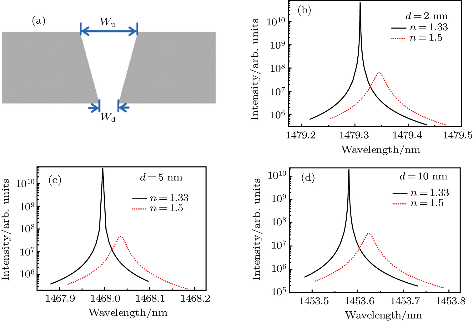 | Fig. 13. (color online) (a) The cross-section of the waged gap. (b)–(d) The scattering spectra for d = 2 nm, 5 nm and 10 nm, respectively. The trapped nanoparticle has n = 1.5 and r = 1.25 nm. |
The case of Wu less than Wd is also studied. When Wu is less than Wd, for example, when d = −1 nm and −2 nm, the spectral shifts are 0.0299 nm and 0.0264 nm, respectively. The spectral shift becomes smaller because of sharpness decreasing for the lower edge of the gap. Moreover, Dantham et al. found that the wavelength shift due to the single protein adsorption mainly depended upon the electric field intensity at the surface of the bump.[4] As a result, the electric field is mainly located at the upper edge, rather than the lower edge of the gap.[54] The coupling between the split ring and the nanoparticle becomes weak and the shift becomes smaller.
We study the optical properties of plasmonic lasing based on the multipolar resonances of a split-ring filled with silica-doped Yb3+: Er3+ ions as the gain material. The quadrupolar resonance of the split ring is located at the 1500 nm emission band of the Er3+ ions and is used as the lasing mode. We tune the hexapolar resonance as the absorption band of 980 nm of the Yb3+ ions for the pumping light mode. The pump light wavelength is shorter than the lasing light by 520 nm and the light intensity in the SRR gap increases by more than 4200 times when the absorptivity of the gain medium reaches the maximum. Thus, SRR plasmonic lasing has special benefits for biomolecular detection with low noise and free from damage caused by intense pump light. The lasing light is amplified by 1010 and the spectrum is as narrow as 0.01 nm. It is very sensitive to a nanoparticle trapped in the SRR gap. When a single nanoparticle is trapped, the lasing wavelength shift accords with the law of Δλ = 0.168n nm when the radius is set as 1.25 nm and Δλ = 0.0184 × r2.54 nm when the refractive index remains at 1.5. Under the experimental detection limit of spectral shift of 10−5 nm, a small molecule with radius of 0.1 nm can be detected by this method. Moreover, the lasing intensity is more sensitive to a trapped nanoparticle than the resonance wavelength shift.
| [1] | |
| [2] | |
| [3] | |
| [4] | |
| [5] | |
| [6] | |
| [7] | |
| [8] | |
| [9] | |
| [10] | |
| [11] | |
| [12] | |
| [13] | |
| [14] | |
| [15] | |
| [16] | |
| [17] | |
| [18] | |
| [19] | |
| [20] | |
| [21] | |
| [22] | |
| [23] | |
| [24] | |
| [25] | |
| [26] | |
| [27] | |
| [28] | |
| [29] | |
| [30] | |
| [31] | |
| [32] | |
| [33] | |
| [34] | |
| [35] | |
| [36] | |
| [37] | |
| [38] | |
| [39] | |
| [40] | |
| [41] | |
| [42] | |
| [43] | |
| [44] | |
| [45] | |
| [46] | |
| [47] | |
| [48] | |
| [49] | |
| [50] | |
| [51] | |
| [52] | |
| [53] | |
| [54] | |
| [55] | |
| [56] | |
| [57] |


