Synchrotron radiation intensity and energy of runaway electrons in EAST tokamak
Zhang YK1, 2, Zhou RJ1, †, Hu LQ1, Chen MW1, 2, Chao Y1, 2, EAST team
Institute of Plasma Physics, Hefei Institutes of Physical Science, Chinese Academy of Sciences, Hefei 230031, China
University of Science and Technology of China,Hefei 230026, China


† Corresponding author. E-mail: rjzhou@ipp.ac.cn

Abstract

A detailed analysis of the synchrotron radiation intensity and energy of runaway electrons is presented for the Experimental Advanced Superconducting Tokamak (EAST). In order to make the energy of the calculated runaway electrons more accurate, we take the Shafranov shift into account. The results of the analysis show that the synchrotron radiation intensity and energy of runaway electrons did not reach the maximum at the same time. The energy of the runaway electrons reached the maximum first, and then the synchrotron radiation intensity of the runaway electrons reached the maximum. We also analyze the runaway electrons density, and find that the density of runaway electrons continuously increased. For this reason, although the energy of the runaway electrons dropped but the synchrotron radiation intensity of the runaway electrons would continue rising for a while.

1. Introduction

In tokamaks, electrons mainly experience two forces, one is the electric field force Fe that can make the electrons accelerate, and the other is the force of collisions with the plasma particles that can decelerate the electrons where γ is the relativistic factor.[1] As the energy of electrons increases, the collision frequency drops rapidly,[2] resulting in a rapid decrease in Fd. When , electrons can be accelerated by the electric field to several tens of MeV or even higher energy in the Experimental Advanced Superconducting Tokamak (EAST).[3]

With the increasing volume of tokamak devices, the energy of runaway electrons is getting higher and higher. In future tokamaks such as ITER, the energy of runaway electrons can even reach 100 MeV.[4] Such high energy electrons can be a serious threat to the tokamak.[5] To study the energy and intensity evolution of these high-energy runaway electrons in experiments, it is extremely important to diagnose the electron parameters effectively and correctly.

In general, the generation of runaway electrons can be divided into two categories: one is in the current ramp-up phase, and the other is during the fast plasma terminations due to plasma disruptions or the killer pellet injection.[6] The runaway electrons generated in fast plasma terminations have a short duration and change rapidly. The frame frequency of the infrared cameras existing on the EAST is low. It is difficult to study the change of runaway electrons. However, the infrared camera can be used to study the evolution of runaway electrons in the current ramp-up phase.

The typical method is measuring the thick-target bremsstrahlung emission or photoneutrons resulting by runaway electrons when they are lost and then impact the limiter or vessel structures. Detection of the synchrotron radiation emitted by runaway electrons by infrared cameras is the best way to diagnose the high-energy runaway electrons which were constrained in the core of the plasma directly.[7] In the current ramp-up phase, the vast majority of high-energy runaway electrons are constrained in the core of the plasma, only a small part of the runaway electrons lost and impact the limiter or vessel structure. In simple terms, detecting the runaway electrons by an infrared camera can reflect the situation of the runaway electrons existing in the plasma better.

In this paper, we carry out detailed analysis of the synchrotron radiation intensity and energy of runaway electrons in EAST. In Section 2, we present the calculation and evolution of the pitch angle of the runaway electrons. In Section 3, we calculate the energy of the runaway electrons. In Section 4, we analyze the evolution of the runaway electron synchrotron radiation and the evolution of the density of the runaway electrons. The conclusions are summarized in Section 5.

2. The pitch angle of the runaway electrons

It is generally defined as , where v and v are the transverse and longitudinal velocities of the runaway electrons respect to the confining magnetic field, respectively, θp is the pitch angle. In general, is a small amount, it can be considered .

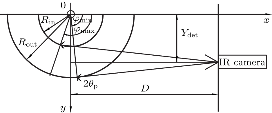
Schematic of the relative positions of the beam of runaway electrons and the infrared camera is shown in Fig. 1. The camera is close to the plasma and viewing tangentially into the plasma from the equatorial plane. The pitch angle of the runaway electrons is θp and the synchrotron radiation is emitted in the range of the apex angle of .

Fig. 1. Relative position of the beam of runaway electrons and the infrared camera in the plane z = 0. Rin and Rout are the inner and outer major radii of the beam.

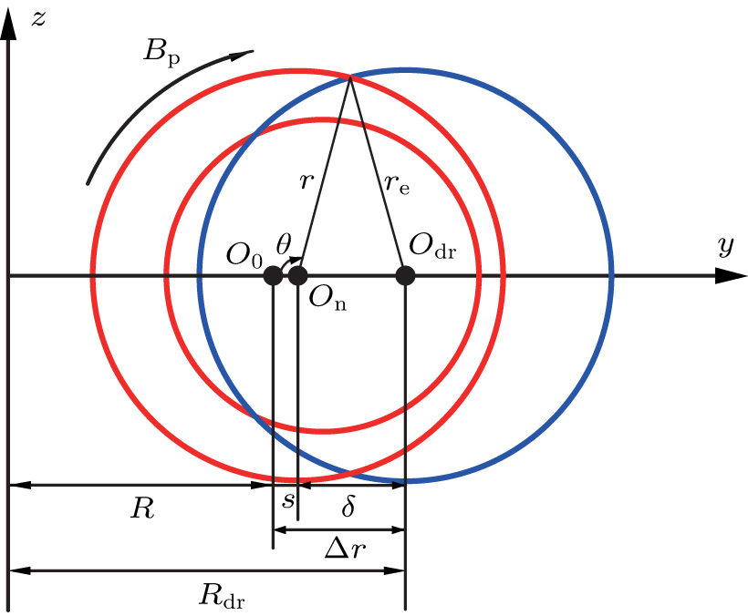
The analytical treatment of the calculation of the synchrotron radiation spot shape from the runaway electrons has been carried out in Ref. [8]. The coordinates we used in the calculation are shown in Fig. 2. The transverse cross sections of the magnetic surfaces and runaway electrons drift orbit are assumed to be nearly circular.

Fig. 2. System of coordinates used in the calculations. The red circle and the blue circle represent the magnetic surface and the drift orbit surface of the runaway electrons, respectively. R is the major radius of EAST. s and δ are the Shafranov shift and the distance of runaway electrons drift orbit from the magnetic surfaces, respectively. O0 is the geometric center of the vacuum vessel.

All the subsequent analyses of the runaway electrons appeared in current ramp-up phase are based on the discharge shown in Fig. 3.

Fig. 3. Time slice of a runaway discharge in EAST. The waveforms are the plasma current, loop voltage, line-averaged density, RA, power of 2.4 G and 4.6 G lower hybrid wave.

Under the above infrared camera and runaway electron beam position conditions, the synchrotron radiation emitted along the runaway electron velocity vector falls into the infrared camera whose conditions satisfy the following equation:[8] where is the range of toroidal angles of the synchrotron radiation that can be recorded by the infrared camera ( ). r presents the distance between O0 and the runaway electrons, the value of r varies at different points, and the average is taken here. v and v are the transverse and longitudinal velocities of the runaway electrons respect to the confining magnetic field, respectively. is usually small, we will omit it; , so we can omit ( . We assume . Then the above formula can be written as and then In the above equations, the upper and lower signs correspond to the cases when the magnetic field is directed away from ( ) and toward ( ) the detector, respectively. is the angle between the horizontal line and the long axis of the asymmetrical synchrotron radiation spot.

As shown in Fig. 4, the βinc angle can be measured from the synchrotron radiation spot of the runaway electrons. In Eq. (3), only θp is unknown, so we can calculate the value of θp. The important parameter θp for the runaway electrons can be obtained from βinc, so βinc is very important. The θp calculated by the above method is the average value of the pitch angle. The evolution of θp is shown in Fig. 5.

Fig. 4. Synchrotron radiation spot from the runaway electron beam recorded by the infrared camera in EAST.
Fig. 5. The pitch angles of the runaway electrons.
3. The energy of the runaway electrons

The energy of the runaway electron beam can be gained from its drift orbit shift. The drift orbit shifts from the magnetic surface by a distance δ, to the first-order approximation,[9] where q is the safety factor, and the runaway electrons exist around the q = 2 rational surface. In the following calculations, the q value is taken to be q = 2.[10] δ is the distance of the runaway electrons drift orbit from the magnetic surfaces, . As shown in Fig. 6 (marked in blue), can be measured from the pictures of the synchrotron radiation spot of the runaway electron beam. Shafranov shift , here we take s = 1 cm. Compared with the in the middle (marked in blue) of the runaway electron beam, most of the at the edge (marked in black) have less than 10% errors (before 1.62 s). The maximum errors (before 1.62 s) of and are less than 15% and 16%, respectively. The toroidal magnetic field . So the average energy of the runaway electrons can be calculated by the following formula:

Fig. 6. Synchrotron radiation spot from the runaway electrons beam in EAST. represents the shift of the center of the runaway electrons orbit. re is the radius of the runaway electrons orbit.
Fig. 7. The evolution of the synchrotron radiation spot emitted by the runaway electrons. The corresponding moments are (a) 1.46 s, (b) 1.52 s, (c) 1.58 s, (d) 1.64 s, and (e) 1.70 s.

As shown in Fig. 8, the energy of the runaway electrons rises before 1.48 s and then decreases. The decrease of the runaway electron energy is due to the increase of the plasma density, which leads to the increase of drag and the decrease of loop voltage, resulting in the decrease of power.

Fig. 8. The energy of the runaway electrons. The energy rises before 1.48 s and then decreases.
4. Synchrotron radiation intensity of the runaway electrons

The synchrotron radiation intensity of the runaway electrons recorded by the infrared camera at pixel A is shown in Fig. 9. The overall trend of synchrotron radiation intensity of the runaway electrons recorded by the infrared camera was enhanced first and then weakened.

Fig. 9. Relationship between the synchrotron radiation intensity, energy, and density of the runaway electrons. They do not reach their maxima at the same time.

In Fig. 9, the synchrotron radiation intensity recorded by the infrared camera and the energy of the runaway electrons do not reach their maxima at the same time. The synchrotron radiation intensity recorded by the infrared camera is related to the energy, density and θp of the runaway electrons in EAST. Taking energy and θp into account, the change of radiation spectra of a single electron between 1.5 s and 1.6 s is small. Furthermore, taking a certain error into account at 1.6 s, the change of the spectrum (from to ) is still small. But the synchrotron radiation intensity observed by the infrared camera varied greatly. So the density of runaway electron certainly increased.

The density of the runaway electrons can be calculated by the synchrotron radiation intensity recorded by the infrared camera and the synchrotron radiation spectra of single runaway electron (Fig. 10) in EAST. The infrared cameras can observe infrared rays in the wavelength range of to . We integrated the spectra from to to obtain the radiation intensity of a single electron. And then the intensity of the synchrotron radiation measured by the infrared camera was divided by the radiation intensity of a single electron to obtain the relative density of the runaway electrons. As shown in Fig. 9, it is clearly that the density of the runaway electrons increased before 1.7 s. As shown in Fig. 3, the increase of the runaway electrons density occurs in the density ramp-up phase. It is possible that the increase of the plasma density leads to the increase of the runaway electrons density, but no strong evidence has been found. During 1.5–1.6 s, the increase of the runaway electrons density led to the synchrotron radiation intensity recorded by the infrared camera increasing though the energy of the runaway electrons decreased.

Fig. 10. The synchrotron radiation spectra of single runaway electron in EAST with R = 1.86 m and . The two vertical dashed lines are and , respectively.
5. Summary

Synchrotron radiation is a powerful tool for diagnosing high-energy runaway electrons that are confined in the core of the plasma. In this paper, we have presented a detailed analysis of the energy, synchrotron radiation intensity, and density of the runaway electrons.

The energy of the runaway electron beam can be gained from its drift orbit shift. The energy of the runaway electrons rose before 1.48 s and then decreased. The decrease of the runaway electron energy is due to the increase of the plasma density, which leads to the increase of drag and the decrease of loop voltage, resulting in the decrease of power.

The synchrotron radiation intensity of the runaway electrons recorded by the infrared camera and the energy of the runaway electrons did not reach their maxima at the same time. The main reason why they did not reach the maximum at the same time is that the density of the runaway electrons was rising when the energy of the runaway electrons began to decrease. The increase of the runaway electrons density led to the synchrotron radiation intensity recorded by the infrared camera increasing though the energy of the runaway electrons decreased.

Reference
[1] Fussmann G 1979 Nucl. Fusion 19 327
[2] Dreicer H 1959 Phys. Rev. 115 238
[3] Zhou R J Hu L Q Li E Z et al. 2013 Plasma Phys. Control. Fusion 55 055006
[4] Bakhtiari M Kramer G J Takechi M et al. 2005 Phys. Rev. Lett. 94 215003
[5] Yoshino R Kondoh T Neyatani Y et al. 1997 Plasma Phys. Control. Fusion 39 313
[6] Esposito B Martın-Solıs J R Poli F M et al. 2003 Phys. Plasmas 10 2350
[7] Jaspers R Lopes Cardozo N J Donne A J H et al. 2001 Rev. Sci. Instrum. 72 466
[8] Pankratov I M 1996 Plasma Physics Reports 22 535
[9] Guan X Qin H Fisch N J 2010 Phys. Plasmas 17 092502
[10] Zhou R J Pankratov I M Hu L Q et al. 2014 Phys. Plasmas 21 063302