Microparticle collection for water purification based on laser-induced convection
Liu Zhi-Hai, Lei Jiao-Jie, Zhang Yu, Zhang Ya-Xun, Yang Xing-Hua, Zhang Jian-Zhong, Yang Yun, Yuan Li-Bo
Photonics Research Center, School of Science, Harbin Engineering University, Harbin 150001, China


† Corresponding author. E-mail: zhangy0673@163.com

Project supported by the National Natural Science Foundation of China (Grant Nos. 11574061, 61405043, and 61675053), the 111 Project, China (Grant No. B13015), and the Fundamental Research Funds for Harbin Engineering University of China.

Abstract

Water purification is required for environmental protection. In this paper, we propose and demonstrate a rapid, effective and low-cost approach to collect numerous impurities (microparticles) in water on the basis of laser-induced thermal convection. We introduce a heat source by using a fiber tip, which is fabricated into a non-adiabatic-tapered shape. In order to improve the laser power absorption efficiency, we coat a gold film with a thickness of 300 nm on the fiber tip. Due to absorption, the laser power transferred from the fiber to the water results in thermal convection. The forces generated from the thermal convection drive the microparticles to move towards the fiber tip, thereby performing microparticle collection and achieving water purification. Laser-induced thermal convection provides a simple, high-efficiency and low-cost method of collecting microparticles, which is a suitable and convenient for local water purification.

1. Introduction

Water purification is strongly related to people’s livelihood and environmental protection. Drinking water is contaminated with thousands of compounds.[1] Some pollutants and disinfection byproducts can be toxic to the human body.[24] Currently, there are numerous ways to purify drinking water. Natural sedimentation[5,6] is commonly used for collecting heavy particles. Biofiltration[7] can be implemented in drinking water filters through its biological treatment function, and protein-like materials can be removed. Electrocoagulation,[810] a process that generates coagulant electrochemically, has been reported to be efficient in removing a wide range of electroplating pollutants from water. Micro- and nanomaterials with unique optical and electrical properties can be used to decompose dyes in water under UV and visible light irradiation.[11] However, these methods are restricted by complex devices and special materials for chemical reactions. Among the various methods used collect the impurities (microparticles) in water, optical trapping[12] is a typical representative. Optical tweezers may trap and manipulate microparticles, whose diameters range from a few nanometers to tens of micrometers.[1316] The magnitude of the optical trapping force is usually on the scale of pN, and the effective trapping range is on the scale of .[17] It is difficult for normal optical tweezers to collect the microparticles in a large space or with a large number. Photophoresis,[1822] thermophoresis,[2326] and thermal convection[27,28] are also used to collect microparticles. However, the complex properties of the microparticles and solution cause uncertainty of the force direction, hindering them from being put to practical use. In this paper, we propose and demonstrate a highly-effective, simple and novel method to accumulate microparticles based on the laser-induced thermal convection effect. This method eliminates the need for complex filtration devices or filter materials, preventing excessive changes in the fluid environment.

The light source power is introduced by a non-adiabatic tapered shape fiber tip with a gold film coating. This gold film helps to absorb the laser power leaking from the fiber tip and transfer it to heat. The heat is absorbed by the water around the fiber tip to perform a temperature gradient distribution, producing convection. The forces generated from the thermal convection drive the microparticles to move from the low-temperature area to the high-temperature area. By using this laser-induced thermal convection method, we can drive numerous microparticles to accumulating quickly and easily. In addition, we can realize microparticle accumulation by using a low input light power because of the high-efficient light energies absorbed by the gold film.

2. Principle of laser-induced convection
2.1. Fiber probe

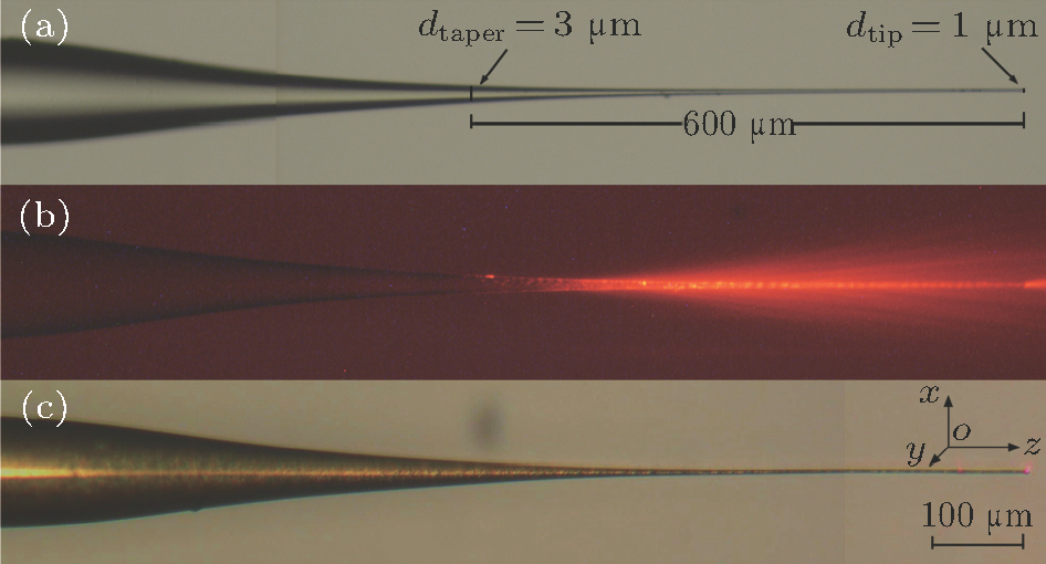
Unlike the heating and tapering procedure of an adiabatic shape fiber tip,[31] a non-adiabatic shape fiber tip was fabricated to ensure the laser power leakage from the fiber (see Fig. 1(a)). The fiber tip was constructed from a normal commercial 1310 nm single mode optical fiber (ClearLite® 1310 Photonic Fibers, OFS). The non-adiabatic tapered shape was fabricated by using normal heat- fused biconical taper technology. The laser power leaked out from the side face of the fiber tip (see Fig. 1(b)). In order to increase the heat and temperature production, we plated a gold film on the optical fiber tapered tip. According to Fig. 1(c), there was a little light outgoing from the fiber tip. A vacuum plasma sputtering method was employed to plate the gold film. The gold film thickness was ∼300 nm, which was measured by a three-dimensional (3D) morphology analyzer (NewView 7200, Zygo©).[32]

Fig. 1. (color online) (a) Non-adiabatic tapered optical fiber tip, (b) laser leakage from the non-adiabatic tapered fiber tip, and (c) non-adiabatic tapered optical fiber tip with gold coating.
2.2. Temperature field distribution

Silica fiber is temperature-insensitive. If the fiber tip is not gold-coated, the temperature increase of the solution is mainly caused by the special wavelength absorption of the water solution. When the laser wavelength is , according to the Beer–Lambert law,[33] the absorbed power can be expressed as , where α is the absorption coefficient of the laser in water,[34] d is the effective absorption depth and I0 is the initial light intensity. When the input power was 9 mW, we calculated the maximum value of the temperature increment ( of the solution near the fiber probe to be 10 K, which was inefficient for microparticle accumulation. Therefore, we employed the gold coating method to enhance the temperature increment.

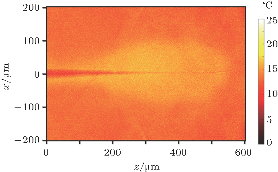
By using the fluorescence dye method, we obtained the temperature distribution near the fiber tip. We employed Rhodamine B as the fluorescence dye. The concentration of Rhodamine B solution was 2 mg/L, whose temperature dependence has been well documented.[35,36] In the measurements, we employed a 532 nm green laser to excite the fluorescence and employed a charge-coupled device (CCD) to obtain the temperature information. Figure 2 shows the experimental results and the is 22.35 K.

Fig. 2. (color online) Experimental results of the temperature field distribution.

The added temperature of water solution near the fiber tip produced a temperature gradient distribution in the solution. Thus, the density of the water solution changed along with temperature distribution, causing the buoyancy lift in unit volume to change,[37] and finally leading to convection in the water solution. The larger the temperature difference was, the stronger the convection was. We could control the microparticle accumulating velocity by changing the temperature distribution, which was finally controlled by the input laser power. Due to the non-adiabatic tapered shape, a great deal of laser power leaked out from the fiber tip. The output laser power was absorbed by the gold coating to generate the heat, which was then absorbed by the water solution near the fiber tip. The absorption of heat produced the temperature gradient distribution near the fiber tip, leading to the convection of the solution. The convection caused the microparticles in the solution to move from the low-temperature area to the high-temperature area, driving the microparticles to move towards the fiber tip and achieving the accumulation.

3. Experiments and results
3.1. Experimental setup

Figure 3 shows the experimental setup. A pump laser with a working wavelength of was used as a light source. The power adjusting range of the laser source was 0 to 100 mW. An optical isolator was employed to protect the laser source. The tapered tip fiber was mounted on a 3D micro-manipulator platform for adjusting the precise position. On the micro-manipulator platform, there was a glass slide with a droplet of water solution full of numerous microparticles. The diameter of each microparticle was . The volume of the water droplet was about 2 mL. The input laser power was 9 mW, the refractive index of the water solution was 1.333 and the refractive index of the fiber core was 1.4681.

Fig. 3. (color online) Schematic of experimental setup.
3.2. Experimental results

Figure 4 shows the experimental results of microparticles accumulating and moving based on the laser-induced thermal convection. When the laser source is off, a few microparticles are randomly distributed near the fiber tip (see Fig. 4(a)). When the laser source is on, the force generated from the laser-induced thermal convection causes the microparticles in the solution to move towards the fiber tip and achieving accumulation (see Fig. 4(b)). When the laser source power is 9 mW, there are ∼180 microparticles accumulating within 180 s. When the laser source is off again, the microparticles remain arranged in the linear shape regardless of whether the fiber moves or not (see Fig. 4(c)). When the laser source power is on again, the microparticles move to the trapping position of the fiber probe again within 40 s (see Fig. 4(d)).

Fig. 4. (color online) (a) Microparticle accumulation when laser source is off. (b) Microparticle accumulation caused by laser-induced thermal convection. (c) Accumulated microparticles remain linear-shape-arranged. (d) The microparticles moving to the optical trapping position of fiber probe again.
4. Discussion

There are some factors affecting the microparticle accumulation.

4.1. Shape of the fiber tapered tip

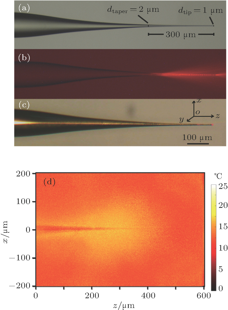
The shape of the fiber tip can affect the distribution of the temperature field, which influences the convection flow field, and finally the microparticle accumulation. Comparing the long non-adiabatic fiber probe tip (being , see Fig. 1), we fabricate a short non-adiabatic fiber tapered tip ( long) to show the difference in microparticle accumulation. The short fiber probes are shown in Figs. 5(a)5(c) and the temperature field distribution of the short fiber probe is shown in Fig. 5(d).

Fig. 5. (color online) (a) Non-adiabatic tapered optical fiber tip, (b) laser leakage from The non-adiabatic tapered fiber tip, (c) non-adiabatic tapered optical fiber tip with gold coating, and (d) experimental results of temperature field distribution.

The results indicate that the shape of the temperature field introduced by the short fiber tip is circular and therefore it accumulates the microparticles and arranges them in a circular shape (see Fig. 6). When the laser source is off, there are few microparticles distributed randomly near the fiber tip (see Fig. 6(a)). When the laser source is on, the force generated from the laser-induced thermal convection causes microparticles in the solution to move towards the fiber tip, achieving accumulation (see Fig. 6(b)). When the laser source power is 9 mW, there are ∼65 microparticles accumulating within 120 s. When the laser source is off again, the microparticles remain round-arranged regardless of whether the fiber moves or not (see Fig. 6(c)). When the laser source power is on again, the microparticles move to the trapping position of the fiber probe again within 90 s (see Fig. 6(d)).

Fig. 6. (color online) (a) Microparticles accumulation when the laser source is off. (b) Microparticle accumulation caused by the laser-induced thermal convection. (c) The accumulated microparticles remain round-shape-arranged. (d) Microparticles moving to the optical trapping position of fiber probe again.

Comparing the microparticle accumulation results between the long and short fiber probe, the accumulating velocity introduced by the long fiber probe was large. In addition, the length of the fiber probe affected the arrangement shape of the accumulated microparticles.

4.2. Thickness of gold coating

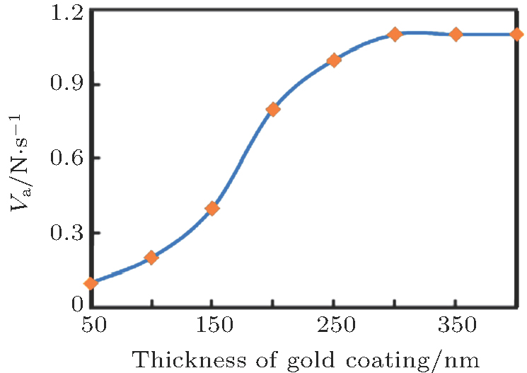
The microparticle-accumulating velocity is related to the thickness of the gold coating. In a range of 0–300 nm, the thicker the gold coating is, the higher the temperature of the solution near the fiber probe is, and the larger the microparticle accumulating velocity is (see Fig. 7).

Fig. 7. (color online) Relationship between microparticle-accumulating velocity (Va) and thickness of gold coating.
4.3. Particle concentration

The microparticle-accumulating velocity (Va) is related to the microparticle concentration (C) in the solution. In our experiment, when the microparticle concentrations were 0.2625 mg/mL, 0.5250 mg/mL and 0.7875 mg/mL respectively, the microparticle accumulating velocities were, respectively, 0.42N s−1, 1.11N s−1 and 1.67N s−1, where N is the microparticle number (see Fig. 8, the laser source power is 9 mW). The results indicate that the accumulating velocity is approximately linearly proportional to the microparticle concentration.

Fig. 8. (color online) Experimental results of microparticle-accumulating velocity (Va) for different microparticle concentrations.
4.4. Laser power

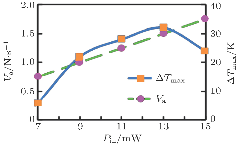
The microparticle-accumulating velocity (Va) is related to the laser source power (Pin). When the microparticle concentration of the solution is 0.5250 mg/mL, we adjust the power of laser source to measure the microparticle-accumulating velocity. Here we choose Pin = 7, 9, 11, 13 and 15 mW, respectively. According to Fig. 9, the larger the laser source power is, the higher is, and the larger the microparticle accumulating velocity is. The accumulating speed is approximately linearly proportional to the laser power. When Pin is higher than 15 mW, the convection in the solution is not dominant and the solution experiences turbulence, which is unsuitable for microparticle accumulation.

Fig. 9. (color online) Measured results of microparticle-accumulating velocity (Va) and the corresponding simulated results of for different laser source powers. Here the depth of the fiber is and the solution concentration is 0.5250 mg/mL.
4.5. Microparticle size

When the density and the kinematic viscosity of the microparticles are fixed, the microparticle-accumulating velocity is related to the microparticle size in the same convection flow distribution field. The distribution of the convection flow is uneven in the vertical (x-axis) direction. The convection velocity is large near the heat source and small near the boundary, including the interface between the air and water surface and the bottom of the substrate. When two microparticles of different sizes are placed on the bottom of the substrate, due to the unevenness of the convection flow distribution near the microparticles, the forces generated from the convection flow are different. The larger the microparticle diameter is, the larger the total force integral of the microparticle surface is, and the larger the microparticles moving velocity is. Figure 10 shows the measured results of the microparticle moving velocity for different microparticle diameters: , , and , respectively. Here Pin = 9 mW and the depth of the fiber . Figure 10 shows that the microparticle-accumulating velocity is proportional to the microparticle diameter.

Fig. 10. (color online) (a) Measured results of the microparticle-accumulating velocity for microparticle diameters of , , and . Here , and C = 0.5250 mg/mL. (b) Schematic diagram of convection flow distribution.
4.6. Convection flow field distribution

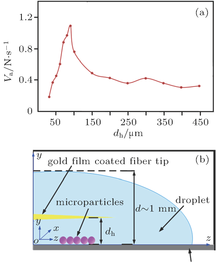
The microparticle-accumulating velocity is also related to the convection flow field distribution. In our experiment, the volume of the water solution is ∼2 mL, and the thickness of the water solution is ∼1 mm (d = 1 mm) (see Fig. 11(b)).

Fig. 11. (color online) (a) Experimental results of microparticle-accumulating velocity (Va) versus dh. Here Pin = 9 mW and C = 0.5250 mg/mL. (b) Schematic diagram of coordinate system used in this paper. Here, dh is fiber depth and d is height (thickness) of water solution.

The depth of the fiber (dh) affects the distribution of the convection flow field, which influences the microparticle-accumulating velocity. We measure the microparticle-accumulating velocity versus dh in a range from to . Here we still take Pin = 9 mW and C = 0.5250 mg/mL. Figure 11(a) shows the measured results. The microparticle-accumulating velocity first increases ( ) and then decreases ( ).When the fiber depth is , the moving velocity reaches .

5. Conclusion

We have successfully demonstrated microparticles accumulating in a water solution on the basis of laser-induced thermal convection. We fabricated a fiber tip into a non-adiabatic tapered shape and plated a gold film on the fiber tip to produce a lot of heat in the solution near the fiber tip. The large heating change produced a temperature gradient distribution in the solution, leading to natural convection. By using this laser-induced convection effect, we could drive numerous microparticles to accumulate quickly, easily and simply. This method provides a rapid and low-cost approach to removing microparticles from a water solution and may be applied to local water purification.

Reference
[1] Schriks M Heringa M B van der Kooi M M E de Voogt P van Wezel A P 2010 Water Res. 44 461
[2] Edwards M Triantafyllidou S Best D 2009 Environ. Sci. Technol. 43 1618
[3] Miranda M L Kim D Hull A P Paul C J Galeano A M O 2007 Environ. Health Persp. 115 221
[4] Yang Y Komaki Y Kimura S Y Hu H Y Wagner E D Mariñas B J Plewa M J 2014 Environ. Sci. Technol. 48 12362
[5] Quik J T K Velzeboer I Wouterse M Koelmans A A van de Meent D 2014 Water Res. 48 269
[6] Hedberg J Ekvall M T Hansson L A Cedervall T Wallinder I O 2017 Environ. Sci. -Nano 4 886
[7] Chen F Peldszus S Elhadidy A M Legge R L Van Dyke M I Huck P M 2016 Water Res. 104 361
[8] Lakshmanan D Clifford D A Samanta G 2009 Environ. Sci. Technol. 43 3853
[9] Mouedhen G Feki M De Petris Wery M Ayedi H F 2008 J. Hazard. Mater. 150 124
[10] Adhoum N Monser L Bellakhal N Belgaied J E 2004 J. Hazard. Mater. 112 207
[11] Yan Y H Zhou Z X Cheng Y Qiu L L Gao C P Zhou J G 2014 J. Alloys Compd. 605 102
[12] Ashkin A 1970 Phys. Rev. Lett. 24 156
[13] Ashkin A Dziedzic J M 1987 Science 235 1517
[14] Grier D G 2003 Nature 424 810
[15] Liu Z H Guo C K Yang J Yuan L B 2006 Opt. Express 14 12510
[16] Bosanac L Aabo T Bendix P M Oddershede L B 2008 Nano Lett. 8 1486
[17] D’Helon C Dearden E W Rubinsztein-Dunlop H Heckenberg N R 1994 J. Mod. Opt. 41 595
[18] Jovanovic O 2009 J. Quant. Spectrosc. Ra. 110 889
[19] Desyatnikov A S Shvedov V G Rode A V Krolikowski W Kivshar Y S 2009 Opt. Express 17 8201
[20] Shvedov V G Rode A V Izdebskaya Y V Desyatnikov A S Krolikowski W Kivshar Y S 2010 Phys. Rev. Lett. 105 118103
[21] Tanaka M Monjushiro H Watarai H 2004 Langmuir 20 10791
[22] Soong C Y Li W K Liu C H Tzeng P Y 2010 Opt. Express 18 2168
[23] Xin H B Li B J 2011 Opt. Express 19 13285
[24] Xin H B Lei H X Zhang Y Li X M Li B J 2011 Opt. Express 19 2711
[25] Duhr S Braun D 2006 Proc. Natl. Acad. Sci. USA 103 19678
[26] Jiang H R Wada H Yoshinaga N Sano M 2009 Phys. Rev. Lett. 102 208301
[27] Ichikawa M Ichikawa H Yoshikawa K Kimura Y 2007 Phys. Rev. Lett. 99 148104
[28] Du F Felts J R Xie X Song J Z Li Y H Rosenberger M R Islam A E Jin S H Dunham S N Zhang C X Wilson W L Huang Y G King W P Rogers J A 2014 ACS Nano 8 12641
[29] Zhang Y Lei J J Zhang Y X Liu Z H Zhang J Z Yang X H Yang J Yuan L B 2017 Sci. Rep. 7 14378
[30] Liu Z H Lei J J Zhang Y Tang X Y Zhang Y X Zhao E M Yang J Yuan L B 2016 J. Opt. Soc. Am. 33 1881
[31] Brambilla G Finazzi V Richardson D J 2004 Opt. Express 12 2258
[32] Liu Z H Wei Y Zhang Y Zhang Y X Zhao E M Yang J Yuan L B 2015 Opt. Lett. 40 2826
[33] Fuwa K Vallee B L 1963 Anal. Chem. 35 942
[34] Xin H B Li X M Li B J 2011 Opt. Express 19 17065
[35] Sakakibara J Adrian R J 1999 Exp. Fluids 26 7
[36] Bermingham J F Chen Y Y McIntosh R L Wood A W 2014 Bioelectromagnetics 35 181
[37] Basu A S Gianchandani Y B 2005 Paroceedings of the 13th International Conference on Solid-State Sensors June 5–9, 2005 Seoul, South Korea 85