


Chaos generation by a hybrid integrated chaotic semiconductor laser
Cite this Article
Zhang Ming-Jiang, Niu Ya-Nan, Zhao Tong, Zhang Jian-Zhong, Liu Yi, Xu Yu-Hang, Meng Jie, Wang Yun-Cai, Wang An-Bang. Chaos generation by a hybrid integrated chaotic semiconductor laser. Chinese Physics B, 2018, 27(5): 050502 
Permissions
Chaos generation by a hybrid integrated chaotic semiconductor laser
† Corresponding author. E-mail:
Abstract
We design a hybrid integrated chaotic semiconductor laser with short-cavity optical feedback. It can be assembled in a commercial butterfly shell with just three micro-lenses. One of them is coated by a transflective film to provide the optical feedback for chaos generation while insuring regular laser transmission. We prove the feasibility of the chaos generation in this compact structure and provide critical external parameters for the fabrication by theoretical simulations. Rather than the usual changeless internal parameters used in previous simulation research, we extract the real parameters of the chip by experiment. Moreover, the maps of the largest Lyapunov exponent with varying bias current and feedback intensity Kap demonstrate the dynamic characteristics under different external-cavity conditions. Each laser chip has its own optimal external cavity length (L) and feedback intensity (Kap) to generate chaos because of the different internal parameters. We have acquired two ranges of optimal parameters (L = 4 mm, 

Keyword:chaotic dynamic characteristics;integrated chaotic semiconductor laser;short-cavity optical feedback;extraction of internal parameters
1. Introduction
Chaos has attracted considerable research interest because of its many potential applications, such as secure communication,[1,2] high-speed random number generation,[3–5] chaotic radar,[6–8] optical fiber detection,[9–11] weak signal detection[12,13] and distributed optical sensors.[14–18] Semiconductor lasers can easily generate chaos[19] with additional degrees of freedom, such as optical feedback, optical injection, electro-optical feedback and mutual coupling.[20–24] Nowadays, most chaotic lasers are fabricated by using discrete optical components in a laboratory. However, such chaotic lasers are bulky and easily affected by the external environment, which is not conducive to their practical application and large-scale production.[25–27] To solve these problems, many research groups have put forward the integrated chaotic semiconductor laser.
Recently, some monolithic integrated chaotic semiconductor laser chips have been reported. A laser chip with optical feedback was developed by Satoshi Sunada et al.,[28] which consists of a distributed feedback laser (DFB), two semiconductor optical amplifiers, a photodiode and a passive ring waveguide cavity. The chaos with a flatness of ±6.5 dB and a bandwidth of 10 GHz was obtained. Wu et al. also proposed a laser chip,[27] which includes a DFB section, a phase section, an amplification section and a high-reflection coating to the face of the amplifier section. The chaotic bandwidth increased to more than 26.5 GHz when using this monolithic integrated structure. Yin et al. researched the generation of wideband chaotic signal and generated a chaotic signal of 36 GHz by using a three-section monolithic integrated semiconductor laser under external optical injection.[29] The development of monolithic integrated chaotic semiconductor laser chips has reduced the size of the chaotic lasers and improved the quality of the chaotic signal. However, the production of monolithic integrated chaotic semiconductor laser chips requires sophisticated and expensive instruments, and every step of the growth process must be strictly controlled, which restricts the mass production of monolithic integrated chaotic semiconductor lasers.
Therefore, it is necessary to design a new simple integrated chaotic laser. The feasibility verification of the structure through numerical simulation is an indispensable step in the design process. In the structure that produces chaos, the short cavity optical feedback structure is easiest to integrate.[30] However, it is very sensitive to the external cavity length and the feedback intensity required for the generation of chaos.[31] A small change of the external conditions may have a significant effect on the dynamic characteristics of this structure. Due to the different internal parameters of different laser chips, the length of the external cavity and the feedback intensity are different. This makes previous simulation methods no longer applicable. And we should utilize real internal parameters in the numerical simulation to ensure that the designed integrated chaotic laser can generate chaos.
In this paper, we propose an easy-to-implement hybrid integrated chaotic semiconductor laser with a short external feedback cavity. The frequency test method of the network analyzer is used for acquiring the internal parameters of the chaotic semiconductor laser chip 1 (CSLC1) and CSLC2, and the extracted parameters are used for the following simulation. We obtain the optimal external cavity length and the optimal feedback intensity for the generation of chaos, corresponding to the different internal parameters of each chip. In addition, the results provide a theoretical foundation for the production of the hybrid integrated chaotic semiconductor lasers.
2. Structural design
2.1. Integrated structure
The structural design is based on the theory of a standard single-mode semiconductor laser subject to external optical feedback. The schematic diagram of the hybrid integrated semiconductor laser is shown in Fig.
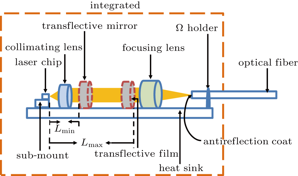 | Fig. 1. (color online) Schematic diagram of the hybrid integrated chaotic semiconductor laser. |
The semiconductor laser chip emits continuous light, which is collimated by the collimating lens and is divided into two parts by the transflective mirror. One part is coupled to the optical fiber, and the other part is reflected to the laser active resonator cavity. The chaotic light is generated by the optical feedback and is finally output by the optical fiber.
2.2. Rate equation model
In theory, the laser active resonator cavity is called the internal cavity, and the structure between the front face of the semiconductor laser chip and the transflective mirror is defined as the external cavity. The chaotic generation with optical feedback can be expressed by the Lang–Kobayashi equations.[32] The equations for the electric field amplitude E(t), the carrier density N(t) and the electric field phase φ (t) are, respectively,
 |
 |
 |
In Eq. (


The internal parameters of the CSLCs that need to be known in Eqs. (
The external cavity frequency is defined as 


The aim of the simulation is to obtain accurate external cavity length L and feedback intensity Kap, and ensure that the fabricated chaotic laser can produce chaos. However, the short-cavity structure is very sensitive to the external cavity length and the feedback intensity. Due to the different internal parameters of different laser chips, the length of the external cavity and the feedback intensity are different. We should utilize real internal parameters in the numerical simulation to ensure that the designed integrated chaotic laser can generate chaos. Therefore, we must extract the internal parameters of the chips.
3. Extraction of the internal parameters
By fitting, we can obtain the Ith and the leaky current

. The Ith is equal to (

, and the

is equal to
.
where

,

and v1, v2 are the relaxation oscillation frequencies and the damping factors at the lower bias level and some higher level, respectively. By fitting, the relaxation oscillation frequencies and damping factors for different bias currents can be obtained. The (2

is equal to

and the v is equal to

.
where α and

are the line width enhancement factor and the chirp frequency, respectively. The fc is equal to

. The

is a parameter that indicates the attenuation characteristics of the optical fiber.
By measuring the P–I curve and the small signal frequency response curve of the CSLC, we can obtain the threshold current, relaxation oscillation frequency and damping factor. These three parameters will be used in the subsequent internal parameter calculation.
The steady-state laser output power versus bias current relationship has been established as
 |
The experimental setup of the small signal intensity modulated frequency response curve is shown in Fig.
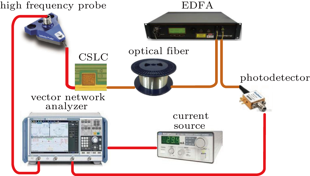 | Fig. 2. (color online) Experimental device diagram for measuring frequency responses. The optical fiber and EDFA are used only to measure the fiber frequency response. |
CSLC1 emits continuous light which is converted into an electrical signal by a photodetector (Finisar, XPDV2120RA, 50 GHz bandwidth). Then, the electrical signal is measured by the vector network analyzer. The measured result is the laser frequency response curve, as shown in Fig.
 | Fig. 3. (color online) (a) The laser frequency responses of CSLC1 for different bias currents. (b) Fitted results when the laser frequency response of 13 mA is subtracted from the laser frequency response for other higher bias currents. (c) Damping factor versus the relaxation oscillation frequency squared (the slope gives a value of 0.3 ns for K-factor). |
The relative frequency response curves can be obtained by subtracting the frequency response at a lower biased current from the ones biased at higher biased current, as shown in Fig.
 |
Figure
The relaxation oscillation frequency squared versus the damping factor is linear, as shown in Fig. 
The threshold current Ith of CSLC1 is 11.3 mA. The active volume 


The light-wave signal generated by CSLC is coupled into the dispersive optical fiber and amplified by an erbium doped optical fiber amplifier (EDFA, KEOPSYS, CEFA-C-HG). The amplified signal is converted into an electrical signal by a photodetector. Finally, the electrical signal is tested by the vector network analyzer. The electrical signal is the fiber frequency response.
The fiber frequency responses use the absolute value on the logarithmic domain with subtraction of the laser frequency response at the same bias current. The obtained curves fit to
 |
The fitted results of the fiber frequency responses of CSLC1 are shown in Fig.
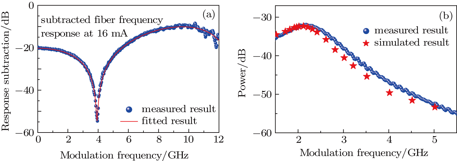 | Fig. 4. (color online) (a) Fiber frequency response subtracts the laser frequency response at 16 mA. (b) Result of simulated laser frequency response (red star) at 13 mA and the measured laser frequency response (blue ball) at the same bias current. |
| Table 1.
Internal parameters of CSLC1. . |
To verify the accuracy of the parameters, we compare the laser frequency response of calculation and experiment at the same bias current, as shown in Fig.
Furthermore, we extract the internal parameters of CSLC2 by experiment, which are listed in Table
| Table 2.
Internal parameters of CSLC2. . |
4. Results and discussion
To obtain an insight into the route to chaos of the system, we present the bifurcation diagram of CSLC1 for 
 | Fig. 5. (color online) Bifurcation diagrams of CSLC1: steady state (A), one-period oscillation (B), two-period oscillation (C), four-period oscillation (D), eight-period oscillation (E). |
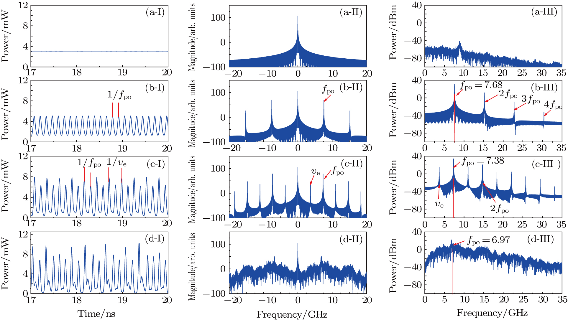
Figure 


 | Fig. 6. (color online) Calculated time series (I), optical spectra (II), and frequency spectra (III) of the chaotic semiconductor laser chip 1: (a) the steady state, 


|
Figure 
As Kap increases from 0.015 to 0.07, the laser appears non-damped oscillations and the system enters the one-period oscillation. As shown in Fig. 


Figure 


The dynamics of CSLC1 at 

Figure 

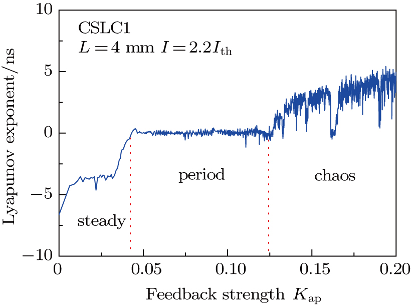
The numerical result of the largest Lyapunov exponent of CSLC1 is shown in Fig. 
 | Fig. 7. (color online) Largest Lyapunov exponent as a function of the feedback strength Kap of CSLC1. Feedback cavity L is 4 mm and bias current I is 
|
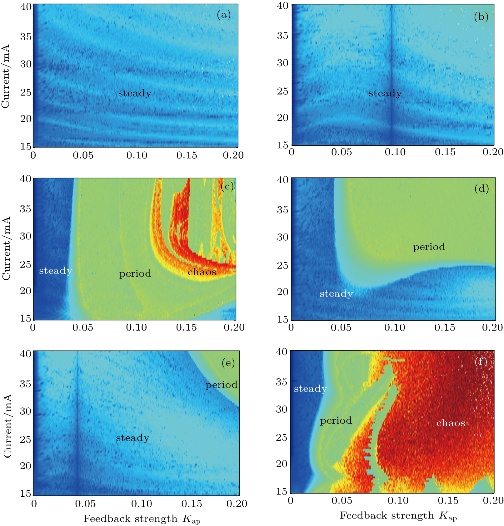
To investigate the comprehensive effects of bias current (15–41 mA) and Kap (0–0.2) on CSLC1, we apply the maps of the largest Lyapunov exponent to estimate the dynamics of this system under different external cavities,[40] as shown in Fig.
 | Fig. 8. (color online) Dynamic maps of the chaotic semiconductor laser chip 1 calculated by the largest Lyapunov exponent: (a) L = 2 mm, (b) L = 3 mm, (c) L = 4 mm, (d) L = 5 mm, (e) L = 6 mm and (f) L = 4 cm. The blue represents that the largest Lyapunov exponent is far less than zero; green is near zero; red and yellow are greater than zero. |
When the external cavity length is equal to 4 mm, the result is shown in Fig. 


When the external-cavity length increases to 5 mm, the chaotic state disappears and the region of steady state increases, which is reflected in Fig. 

When L = 4 cm, the external cavity frequency 


Figure 

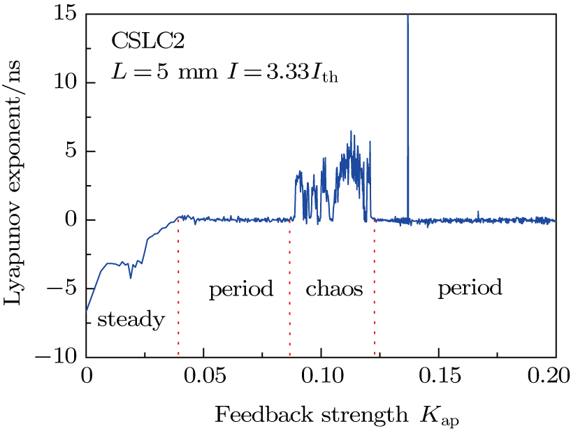 | Fig. 9. (color online) Largest Lyapunov exponent as a function of the feedback strength 

|
Figure
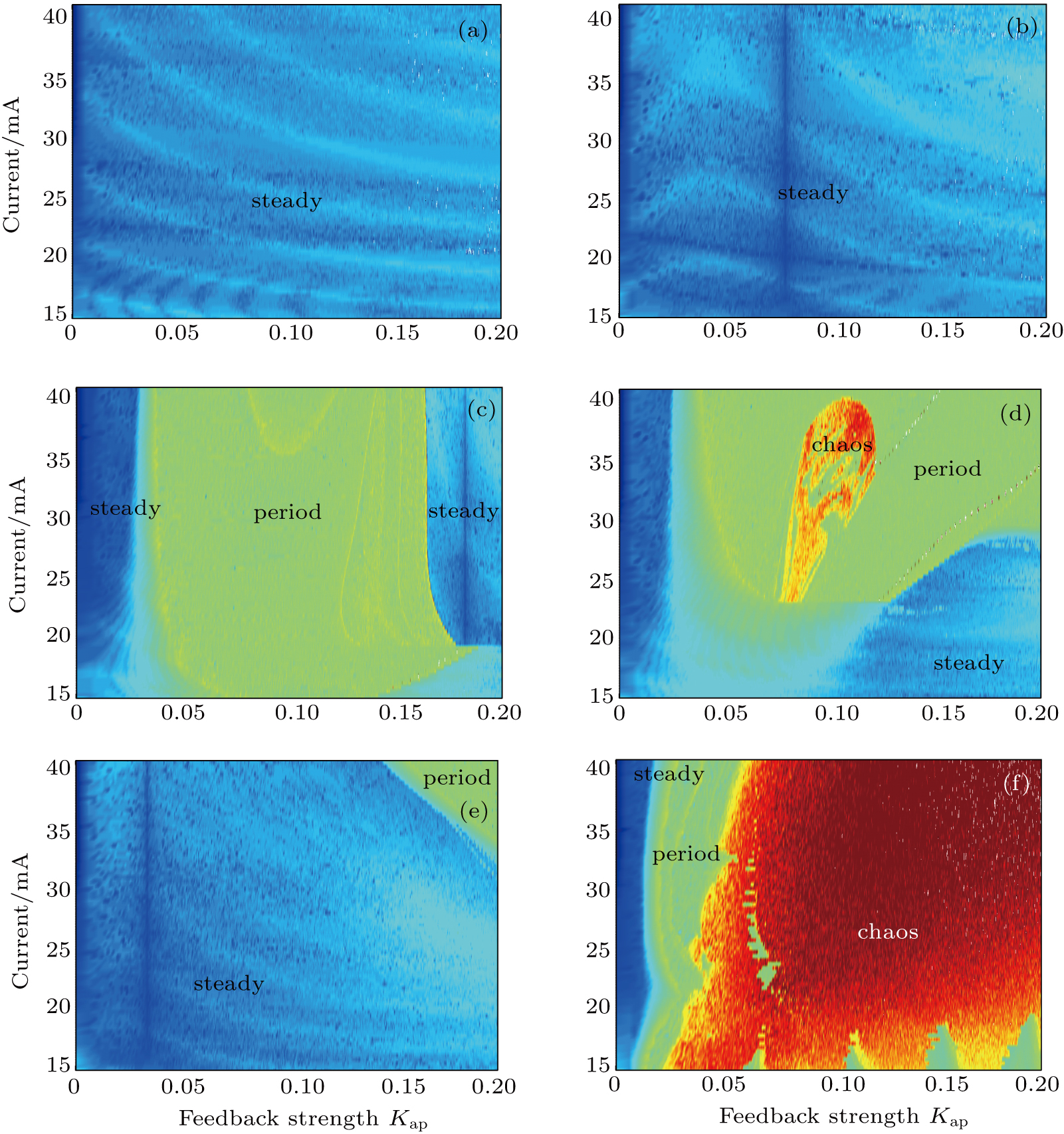 | Fig. 10. (color online) Dynamic maps of the chaotic semiconductor laser chip 2 calculated by the largest Lyapunov exponent: (a) L = 2 mm, (b) L = 3 mm, (c) L = 4 mm, (d) L = 5 mm, (e) L = 6 mm, and (f) L = 4 cm. The blue represents that the largest Lyapunov exponent is far less than zero; green is near zero; red and yellow are greater than zero. |
When the external cavity length is equal to 5 mm (Fig. 
When the length of the external cavity increases to 6 mm, the region of steady state increases and the period-doubling state reduces, which are reflected in Fig.
The results of this section are obtained by theoretical simulation. We prove the feasibility of this structure by a great mass of theoretical simulations. For a long cavity, we can find that the external-cavity length and the feedback strength have little effect on different chips to generate chaos by comparing the dynamic maps in Figs. 
The route to chaos of this structure is systematically investigated. The results show that when 


5. Conclusion
We propose a hybrid integrated chaotic semiconductor laser with short-cavity optical feedback. This is a new structure to achieve integration through a simple, low-cost manufacturing process, and it is more conducive to mass production of integrated chaotic semiconductor lasers. To make the simulation results more accurate, we extract the internal parameters of the chaotic semiconductor laser chips (CSLCs) and utilize them for numerical simulation. Based on this method, we can provide accurate external cavity length and feedback intensity for the fabrication of the hybrid integrated chaotic laser and ensure that it can generate chaos. Practically, we have fabricated a hybrid integrated chaotic laser in collaboration with the Institute of Semiconductors of the Chinese Academy of Science.[41] And the experimental phenomena agree well with the theoretical prediction.
We propose the method of combining extraction parameters with numerical simulation for the first time. This study lays a theoretical foundation for the fabrication of hybrid integrated chaotic semiconductor lasers with short-cavity optical feedback.
Reference
| [1] | |
| [2] | |
| [3] | |
| [4] | |
| [5] | |
| [6] | |
| [7] | |
| [8] | |
| [9] | |
| [10] | |
| [11] | |
| [12] | |
| [13] | |
| [14] | |
| [15] | |
| [16] | |
| [17] | |
| [18] | |
| [19] | |
| [20] | |
| [21] | |
| [22] | |
| [23] | |
| [24] | |
| [25] | |
| [26] | |
| [27] | |
| [28] | |
| [29] | |
| [30] | |
| [31] | |
| [32] | |
| [33] | |
| [34] | |
| [35] | |
| [36] | |
| [37] | |
| [38] | |
| [39] | |
| [40] | |
| [41] |