Design of small-scale gradient coils in magnetic resonance imaging by using the topology optimization method
Pan Hui1, 2, Jia Feng3, †, Liu Zhen-Yu1, ‡, Zaitsev Maxim3, Hennig Juergen3, G Korvink Jan4
Changchun Institute of Optics, Fine Mechanics and Physics, Chinese Academy of Sciences, Changchun 130033, China
University of Chinese Academy of Sciences, Beijing 100049, China
Deptartment of Radiology, Medical Physics, Medical Center University of Freiburg, Faculty of Medicine, University of Freiburg, Freiburg 79106, Germany
Institute of Microstructure Technology, Karlsruhe Institute of Technology (KIT), Karlsruhe 76344, Germany


† Corresponding author. E-mail: feng.jia@uniklinik-freiburg.de liuzy@ciomp.ac.cn

Abstract

A topology optimization method based on the solid isotropic material with penalization interpolation scheme is utilized for designing gradient coils for use in magnetic resonance microscopy. Unlike the popular stream function method, the proposed method has design variables that are the distribution of conductive material. A voltage-driven transverse gradient coil is proposed to be used as micro-scale magnetic resonance imaging (MRI) gradient coils, thus avoiding introducing a coil-winding pattern and simplifying the coil configuration. The proposed method avoids post-processing errors that occur when the continuous current density is approximated by discrete wires in the stream function approach. The feasibility and accuracy of the method are verified through designing the z-gradient and y-gradient coils on a cylindrical surface. Numerical design results show that the proposed method can provide a new coil layout in a compact design space.

1. Introduction
1.1. Application in magnetic resonance imaging

Magnetic resonance imaging (MRI) is widely used in medical diagnosis, biological research, and material science. In recent years, it has been used on a microscale with spatial resolutions of less than typically in magnetic resonance microscopy (MRM),[1] and micro-total analysis systems ( TAS).[2] For imaging the mass-limited or volume-limited samples, there is a challenge due to the huge reduction in signal-to-noise ratio (SNR).[3] The increasing of imaging spatial resolution and signal sensitivity is critical to the improvement of MRI. According to the principle of MRI, the SNR of imaging is mainly limited by the signal of RF coils and the strength of main magnetic field. Imaging spatial resolution can be improved by increasing the gradient strength of the magnetic field generated by the gradient coils.

Recently, a great deal of research has been reported for rapid switching and high-resolution MR devices on a microscale for cell imaging. This research focuses on the miniaturization of core components of MRI equipment. Most of the studies are aimed at the downscaling of MR receiver coils, which can enhance the local SNR.[2,47] The gradient value of the gradient magnetic field is also a key factor restricting the quality of imaging. The miniaturization of the gradient coil reduces the distance between the coil and the sample, improves the efficiency of the coil, and increases its gradient value. In this paper, we will discuss gradient coils for microscale MRI applications. Whether there are simple and efficient micro coil configurations is an open question. In this paper, voltage-driven gradient coils are proposed, which are designed by a topology optimization method. The method offers a means to design custom coils with best performance.

1.2. Conventional gradient coils

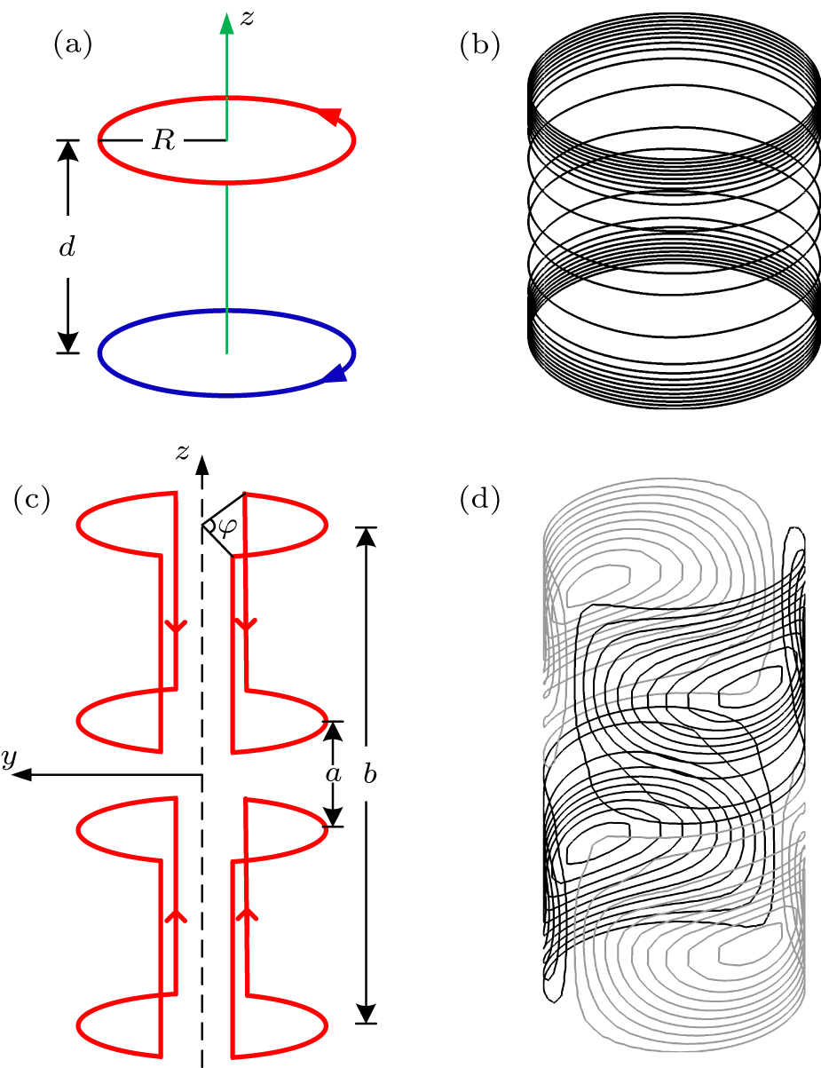
To date, much research has focused on improving the performance of gradient coils. The reported design methods can be divided into two types: discrete wire techniques and current density techniques.[8] Discrete wire techniques are based on the optimization of the geometry (size/position) of independent current loops to produce a required magnetic field. The most basic examples of the discrete wire techniques are the Maxwell coil (Fig. 1(a)) for longitudinal direction gradient coils, and the Golay coil (Fig. 1(c)) for transverse direction gradient coils. The Maxwell coil can be constructed by two coaxial windings spaced by , with opposite currents, on a cylindrical surface. The deviation of produced magnetic field from the ideal field within a sphere of radius 0.5R is less than 5%. The Golay coil, which includes two pairs of arcs with radius R and geometry parameter φ = 120°, a = 0.78R, and b = 5.13a, can generate a y-gradient magnetic field with the deviation less than 5%, in a sphere of radius 0.4R. In order to improve the gradient linearity, optimization techniques, like conjugate gradient descent[9] and simulated annealing,[10] have been introduced to solve for various coil parameters.

Fig. 1. (color online) Conventional gradient coils: (a) Maxwell coil, (b) z-gradient coil calculated by stream function method, (c) Golay coil, and (d) y-gradient coil calculated by stream function method.

The current density techniques compute a continuous current distribution which needs to be approximated by discrete wires or current paths. A number of optimization methods have been developed in order to determine the current density distribution. These include the target field method[1114] and the stream function method.[1518] The target method developed by Turner[19] uses a Fourier–Bessel expansion of the magnetic field generated by current flowing on a cylindrical surface, and uses Fourier transforms to obtain an ideal current density solution. The stream function method is based on meshing the current carrying surface into an array of finite elements to approximate distributions of stream functions, where the current density vector design variables are transformed into scalar design variables. The numerical methods mainly include finite difference method,[20] finite element method (FEM),[21] and boundary element method.[16] These types of techniques have been extended by optimizing some features of coils, such as the inductance,[22,23] stored magnetic energy,[2426] dissipated power,[2729] torque,[30] coil width, and nonlinear gradient coils.[31] The current density techniques generally lead to more compact coils resulting in increased efficiency, as well as less concentrated current resulting in lower inductance.[32] Figures 1(b) and 1(d) show the gradient coils designed by a stream function method for longitudinal gradient coils and transverse gradient coils, respectively.[33] Comparing with the gradient coils designed by discrete wire techniques, the differences in winding shape are immediately obvious.

Even though the current density technique is successful in designing the MR gradient coils, it also has some limitations. Firstly, the current distribution derived by these methods must be approximated by discrete wires or current paths. As for small numbers of wires, the approximation to the current distribution is poor, resulting in deviation of the calculated magnetic fields. Secondly, return paths must be introduced to assure that equal currents flow in all paths. The return currents in these wires produce a smaller negative field which reduces somewhat the gradient achievable, and lead to a longer geometry for the current-carrying surface and a higher inductance. Thirdly, the complexity of the configuration increases the difficulty in making gradient coils for microscale MRI.

1.3. Topology optimization method

Topology optimization can be defined as a method with material suitably placed within a prescribed design domain in order to minimize or maximize the given objective function subject to userʼs specified design constraints.[34] The method as a design process has spread to a wide range of applications in different fields of engineering over the years, such as mechanical structures,[35,36] heat conduction,[36] unsteady incompressible Navier–Stokes flows,[38] and multi-physics actuators.[39,40]

In this paper, a method based on the topology optimization of a material distribution is proposed to optimize the configuration of gradient coils, and a gradient-based optimization technique is utilized to solve the design problems. The coil configuration can be obtained, avoiding the usual system errors which may appear in a discrete approximation between the calculated continuous current density and the practical realization of discrete current paths. There is also no presetting limit to the shape of coil configurations.

2. Method

In this section, the proposed topology optimization method (TOM) of designing the gradient coils is discussed in detail. The design process can be divided into two main steps. The first step is to establish the relationship between the surface current and the design variables via a description of the gradient coil, and then to derive the performance parameters of the electromagnetic coil, such as the magnetic field and energy consumption. The second step is to find the optimal coil configuration under a particular application by optimization procedure. Here, the design of gradient coils on a cylindrical surface serves as an example. In order to simplify the optimization model and reduce the amount of calculation, the developable property of a cylindrical surface and the layout symmetry of gradient coils are utilized. The proposed method can also be extended to other geometries or physical boundary conditions.

2.1. Physical problem formulation in continuous form
2.1.1. Layout symmetry and boundary conditions of gradient coils

As shown in Fig. 1, due to the symmetry of the desired gradient magnetic field, conventional gradient coils are symmetric with respect to the planes x = 0, y = 0, and z = 0. Similarly, the developed surface is divided into eight subdomain ( ), (Fig. 2). In order to reduce the amount of calculation, the coil configurations of one eighth of the developed design surface Ω1 are calculated in the optimization process, and the rest can be obtained by symmetry.

Fig. 2. (color online) Current-carrying surface , region of interest (ROI), and the developed design surface. The subdomain Ω1 is used for optimization, where and r0 is the radius of .

Before optimization, the method of driving the gradient coils and boundary condition specifications of the design domain must be determined. For the traditional stream function design method, the electric current drive mode is typically used and the electric current is calculated directly by using the gradient of the stream function. Then the analytical Biot–Savart equation is used to calculate the magnetic field under the given current distribution. For the proposed method, the design variables of the gradient coil are the conductor distribution of gradient coil on the design surface. Therefore, the electric problem has to be solved numerically (here the finite element method is used) under either voltage or current boundary condition. Compared with the current boundary conditions, the voltage boundary conditions can be straightforward implemented based on the standard finite element solution. In this paper, the proposed gradient coil is driven by applying a voltage at a predefined position. For different types of gradient coils, the input voltage can be specified by the designer as shown in Fig. 3.
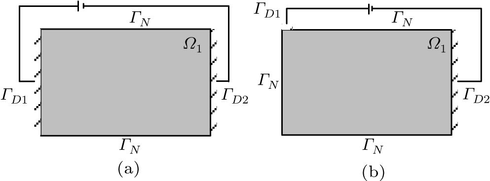
Fig. 3. Boundary conditions of design subdomain Ω1 for (a) z-gradient coils and (b) y-gradient coils.

The z-gradient magnetic field can be produced by a circumferential current, so the input voltage for z-gradient coils can be applied to the left and right ends of the developed design surface. The corresponding boundary condition of subdomain Ω1 is shown in Fig. 3(a), with electric potential boundary conditions, connected to ground, and electrically insulation boundary conditions.

As shown in Figs. 1(b) and 1(d), a linear gradient in the transverse (x, y) direction requires a slightly more complicated conductor geometry, and can be produced by four symmetric arcs or windings, spaced appropriately on a cylindrical surface. Here, the boundary conditions of Fig. 3(b) is chosen for y-gradient coils. By adjusting the position of the input voltage boundary , different coil configurations can be obtained.

2.1.2. Distribution of conductive material

In this paper, the design variable ρ is not the current density or the stream function, but the spatial distribution of conductive material, which is reflected in the conductivity of the gradient coils. The distribution is described by the density field that can take either the value 0 (void) or 1 (solid material) at any point x in the design domain Ω. Intermediate density values are not expected to appear in the final designed coils. In order to enforce binary design variables, the electrical conductivity is expressed using the solid isotropic material with penalization (SIMP) interpolation scheme,[41,42] which is given as

where p is the penalization parameter. In order to obtain a usable design result, typically p is not less than 3, is the conductivity of copper, and is the conductivity of air.

2.1.3. Current continuity equation

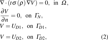
The electric problem is analyzed in the design domain Ω, together with boundary conditions on . It is assumed that the internal electric current source is zero, so that the current continuity equation can be expressed as

where t is the thickness of current-carrying surface, V is the distribution of electric potential, and the boundary conditions are shown in Fig. 3. Because the necessary input voltage for satisfying the design objective is unknown before the optimization procedure, equation (2) is solved with a unit voltage input, and the necessary input voltage is set up as an additional design variable . The unit input voltage is applied to , and is set to ground ( , ). The x and y components of the surface current density on the cylindrical surface under unit voltage input are

2.1.4. Biot–Savart method and objective of optimization

The z-component of the magnetic field at the ith point (xi, yi, zi) inside the region of interest (ROI) can be calculated from the following equation by using the Biot–Savart method:

where and .[25] Because the current continuity equation is a linear problem, the z-component of the magnetic field under voltage input can be expressed as

The goal of the optimization procedure is to find a conductive material distribution in the design domain Ω in order to minimize the objective function for magnetic field linearity, which is defined as the least-square form of the residual between the actual magnetic field and the desired magnetic field

where is the z-component of the desired magnetic field at the ith point inside the ROI, and m is the total number of sampling points inside the ROI.

2.2. Numerical discretization of the optimization model using the FEM

Through the analysis above, the relationship among the magnetic field strength, the current density, and the design variable is established. The formulation is based on the regular discretization of the design domain Ω that is covered by a given shape. Here, the continuous material distribution is approximated by C 0-continuous finite elements in the design domain. The density variable can be expressed as

where is a vector of shape functions, whose components are , is the nodal shape function of the C 0-continuous finite elements, is a vector of nodal design variables , and n is the total number of nodes. By using an FEM discretization, equation (2) can be written as
where is a vector of the corresponding value of nodal electric potentials Vi , and the distribution of electric potential can be expressed as is a vector with applied boundary conditions; is n × n global conductivity matrix, which is assembled in the usual way as the summation over element conductivity matrices
where ne is the total number of elements in the design domain. Therefore, equation (4) can be expressed as

In order to obtain a binary configuration, it is common to choose an auxiliary objective function, such as the resistance, input voltage , or the energy consumption. In this paper, we use the minimum resistance. Under unit voltage boundary conditions, the coil resistance can be calculated from

where is the dissipated power. Its discrete form can be written as
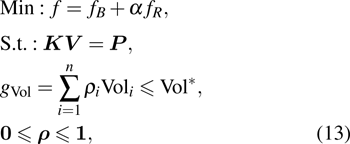
Based on the above arguments, the optimization model can be written as
where is the normalized objective function for relative residual of magnetic field, is the normalized objective function for resistance, with and being the corresponding objective function value under initial design variables α is the weight coefficient of the objective function of resistance; is the node volume fraction; is the constraint on the material volume fraction.

2.3. Optimization procedure

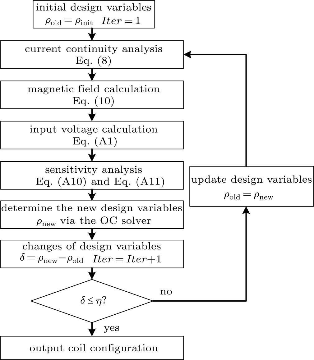
The optimization problem can be solved iteratively by using the gradient-based optimization schemes. In this paper, the gradients with respect to the design variable are obtained using adjoint analysis. The detailed sensitivity derivation is given in the appendix. In each iteration, the following computational steps are performed:

i) Solve the current continuity equation (8) for the unknown electric potential vector.

ii) Perform objective function and sensitivity analysis to obtain the derivatives of the objective and constraint function with respect to the design variable Eqs. (A10) and (A11).

iii) Update the design variable based on the optimality criterion (OC) method[43] or method of moving asymptotes (MMA).[44] In this paper, we will use a standard OC method, because there is only one design constraint about material volume fraction.

The procedure has converged when the changes of design variable δ for subsequent iterations are less than a threshold η (typically 103). We detail the optimization process in Fig. 4.

Fig. 4. Flow chart of the optimization process.
3. Results

For the applications of microscale MRI, the gradient coil is designed on a cylindrical surface as shown in Fig. 2, with a length–diameter ratio of 1, radius of 10 mm, height of 20 mm, thickness t of 1 mm, and radius of the ROI of 5 mm. The design subdomain and boundary conditions are described in Fig. 3(a). The design subdomain is discretized with 10240 rectangular elements, and the ROI is discretized using a relatively regular mesh with 997 nodal points. The desired gradient magnetic field, for z-gradient coils or for y-gradient coils and the gradient value of Gz and Gy is set to be 0.01 T/m.

Here, the field inaccuracy is defined as the linear gradient deviation of magnetic field

Usually, in order to satisfy the requirement for the MRI engineering, is less than 5% and for y-gradient coils in defined in the same way.

3.1. Single-objective optimization

The most straightforward optimization model is the single objective model, where the weight coefficient α in Eq. (13) is equal to zero. It is known that the non-convex least-square objective function may suffer bad optimization procedure. The optimal configuration of z-gradient coil is circles as shown in Figs. 1(a) and 1(b). Figure 5 gives the optimized z-gradient coil configurations with different parameters, and their necessary input voltages and field inaccuracies are shown in Table 1. Since there is no constraint on the input voltage, when the intermediate density is present, the desired magnetic field strength can be obtained by increasing the necessary input voltage.

Fig. 5. One-eighth final configurations of z-gradient coils using single objective optimization model with different parameters.
Table 1.

Input voltage and field inaccuracy of gradient coils listed in Fig. 5.

.

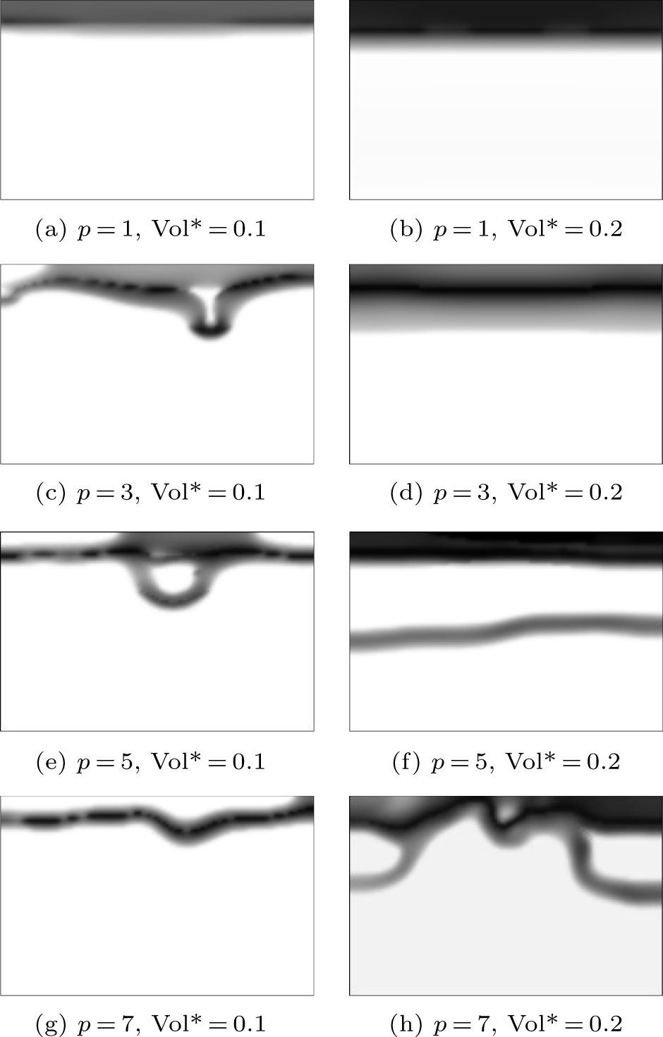
Figure 6 shows the optimized y-gradient coils with . In the SIMP interpolation method, the penalty parameter p is used to obtain the nearby black-and-white designed results. When penalty parameter p is set to be 1, there is an intermediate density value in the result, which is not expected to appear in the final designed coils. As shown from the results, for single-objective optimization, increasing the value of p cannot help the optimization procedure to converge to a binary result, but coils oscillate significantly.

Fig. 6. One-eighth final configurations of y-gradient coils using single objective optimization model with , (a) p = 1, (b) p = 3, (c) p = 5.

In physical terms, due to the lack of accurate constraints on input voltage for the desired magnetic field, design variables can hardly converge to the binary configuration. In other words, minimizing the input voltage (or its equivalent, such as resistance and dissipated power) is necessary for the optimal result to converge to a black-and-white pattern in the proposed optimization model. In this paper, in order to obtain a reasonable optimized result, the auxiliary objective function is introduced into the optimization model with non-zero weight coefficient α.

3.2. Two-objective optimization
3.2.1. Topology optimization of z-gradient coils

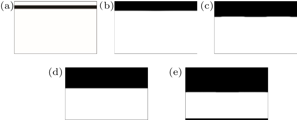
Figure 7 shows the final optimal coil configurations of z-gradient coils with volume fractions ranging from 0.1 to 0.5 and the weight coefficient α =100. The performances of design coils are presented in Table 2.

Fig. 7. Final configurations of z-gradient coils with the volume fractions ranging from 0.1 to 0.5, Here, the weight coefficient α of resistance objective function is chosen as 100 and p = 5.
Table 2.

Performance parameters of z-gradient coils presented in Fig. 7.

.

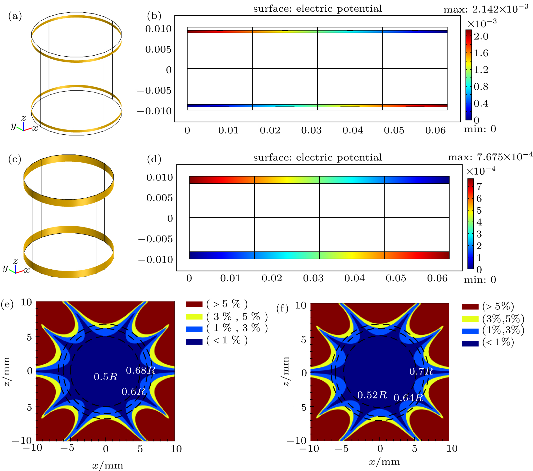
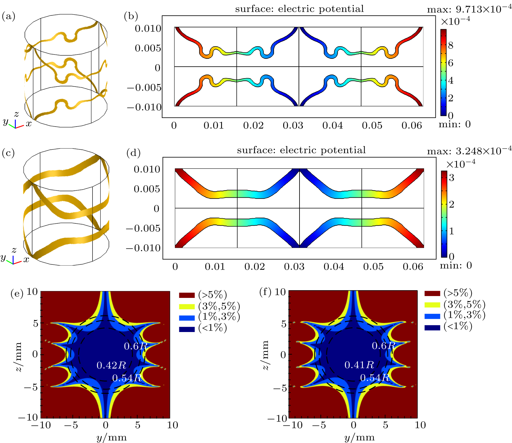
From Table 2, it can be found that the total current required for a given magnetic field distribution is constant, which indicates that all optimal coils have the same gradient efficiency. Increasing the volume fraction of conductive material can help to reduce the current concentration, inductance, and resistance. However, due to the limited length of the current-carrying surface, as the volume fraction increases, useless material which does not contribute to the creation of a linear magnetic field, is distributed at the lower boundary (Fig. 7(e)). Since the normalized objective function is used, the increasing of volume fraction can result in an increase in the weight of resistance objective function, so that the gradient linearity becomes worse. Figure 8 shows the complete configuration of the optimal z-gradient coil presented in Figs. 7(a) and 7(b), and the corresponding distribution of electric potential. Figures 8(e) and 8(f) show the gradient field inaccuracy contours in Figs. 8(a) and 8(c), the field inaccuracy of the red part is more than 5%, and the ROIs with field inaccuracies less than 5%, 3%, and 1% are shown by the dashed circles. It can be seen that the coil configuration is almost identical to a Maxwell coil (shown in Fig. 1(a)), which verifies the effectiveness and accuracy of the proposed method.

Fig. 8. (color online) Configurations of the optimal z-gradient coil presented in Figs. 7(a) and 7(b) on the current-carrying surface, together with the corresponding distributions of electric potential. Panels (e) and (f) show the corresponding gradient field inaccuracy contours of panels (a) and (c) in xz section. R is radius of current-carrying surface.
3.2.2. Topology optimization of y-gradient coils

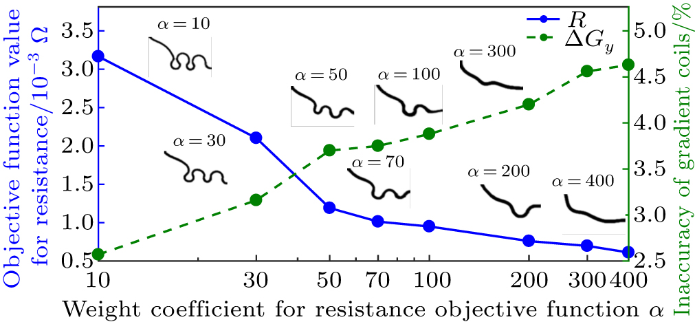
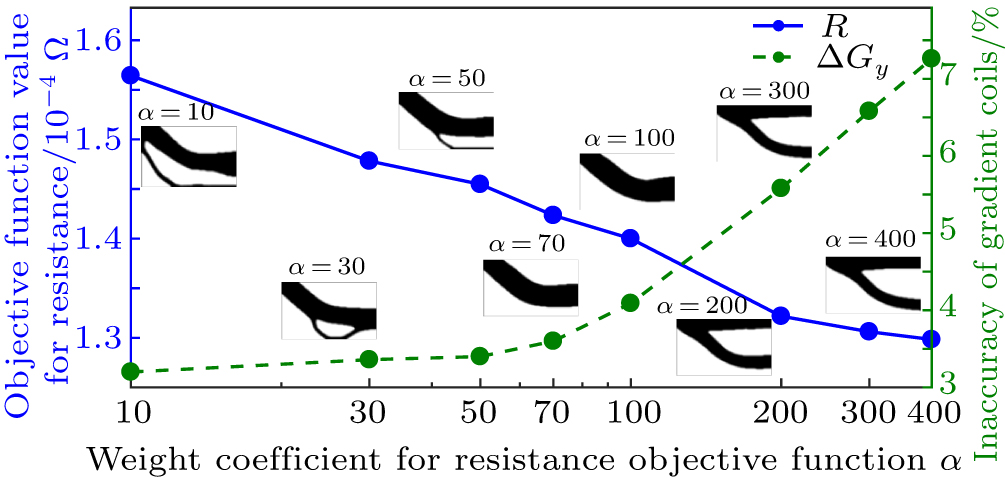
By adjusting the weight coefficient α, a series of different coil configurations can be obtained. Figures 9 and 10 show the plots of the weight coefficient α dependent objective function value for resistance and magnetic field, and the corresponding coil configurations with a volume fraction and 0.4, respectively. As the weight coefficient increases, the coil configuration becomes smoother, but the linearity of the gradient magnetic field becomes worse.

Fig. 9. (color online) Plots of weight coefficient for the resistant objective function α dependent objective function value for resistance and accuracy of the magnetic field, and the corresponding coil configurations ( , p = 5).
Fig. 10. (color online) Plots of weight coefficient for the resistant objective function α dependent objective function value for resistance and accuracy of the magnetic field, and the corresponding coil configurations ( , p = 5).

Figure 11 shows the optimal y-gradient coil configurations with volume fractions of 0.1–0.4 when the weight coefficient is α =100. The corresponding parameters of the gradient coils are listed in Table 3. It shows that an increasing volume fraction results in smoother coil configuration. The complete y-gradient coils and their corresponding electric potential distributions, with volume fractions of 0.1 and 0.2, are shown in Fig. 12. Figures 12(e) and 12(f) show the gradient field accuracy contours of Figs. 11(a) and 11(c), the field inaccuracy of the red part is more than 5%, and the ROIs with field inaccuracy less than 5%, 3%, and 1% are shown by the dashed circles, respectively.

Fig. 11. Coil configurations of y-gradient coils with volume fractions of (a) 0.1, (b) 0.2, (c) 0.3, and (d) 0.4. Here α =100 and p = 5.
Fig. 12. (color online) Configurations of optimal y-gradient coil presented in Figs. 11(a) and 11(b) on the current-carrying surface, together with the corresponding distributions of electric potential. Panels (e) and (f) show the corresponding gradient field inaccuracy contours of panels (a) and (c) in yz section.
Table 3.

Performance parameters of z-gradient coils presented in Fig. 11.

.

Compared with conventional y-gradient coils, the coil configurations are much simple, easy to make on a microscale, with very low inductance and resistance. The required current value is larger, because the magnetic field is produced by a single wire. However, due to the small resistance, the coil can be driven with a relatively small voltage.

4. Conclusion

In this paper, a voltage-driven gradient coil with the conductive material distribution as a design variable, is proposed and optimized by the topology optimization method. Compared with the traditional stream function method, the proposed method avoids magnetic field deviations caused by the discrete approximation of coils. Optimal gradient coils have a much simpler pattern without windings of multi-turn wire. It is thereby possible to effectively reduce the length required for the gradient coil and improve the space utilization of the magnetic resonance system. The proposed method is suitable for designing the gradient coils of microscale MRI gradient coils. Even though the proposed method is still in its infancy, the preliminary design results have shown that it has advantages that the stream method cannot match.

There is still some work to do on further improving the optimization model. For example, multi-objective optimization of the gradient coils can be achieved by introducing other performances of the gradient coils, such as inductance and torque. A closed y-gradient coil can be obtained by adjusting the position of the input voltage.

Reference
[1] Mansfield P Grannell P K 1975 Phys. Rev. 12 3618
[2] Badilita V Kratt K Baxan N Mohmmadzadeh M Burger T Weber H Elverfeldt D V Hennig J Korvink J G Wallrabe U 2010 Lab. Chip 10 1387
[3] Peck T L Magin R L Lauterbur P C 1995 J. Magn. Reson. 108 114
[4] McFarland E W Mortara A 1992 Magn. Reson Imaging 10 279
[5] Rogers J A Jackman R J Whitesides G M Olson D L Sweedler J V 1997 Appl. Phys. Lett. 70 2464
[6] Kratt K Badilita V Burger T Mohr J Börner M Korvink J G Wallrabe U 2009 Sensors. Actuat. APhys. 156 328
[7] Dohi T Murashige K 2016 Micromachines 7 67
[8] Turner R 1993 Magn. Reson Imaging 11 903
[9] Wong E C Jesmanowicz A Hyde J S 1991 Magn. Reson. Med. 21 39
[10] Crozier S Forbes L Doddrell D 1994 J. Magn. Reson. 107 126
[11] Turner R 1986 J. Phys. D-Appl. Phys. 19 L147
[12] Liu W T Zu D L Tang X 2010 Chin. Phys. 19 018701
[13] Bai Y Wang Q Yu Y Kim K 2004 IEEE T. Appl. Supercon. 14 1317
[14] Hu G Ni Z Wang Q 2012 IEEE T. Appl. Supercon. 22 4900604
[15] Tomasi D 2001 Magn Reson Med 45 505
[16] Poole M Bowtell R 2007 Concepts Magn. Reson. B-Magn. Reson. Eng. 31B 162
[17] Hu Y Wang Q L Li Y Zhu X C Niu C Q 2016 Acta Phys. Sin. 65 218301 in Chinese
[18] Wang L Cao Y H Jia F Liu Z Y 2014 Acta Phys. Sin. 63 238301 in Chinese
[19] Turner R 1988 J. Phys. E-Sci. Instrum. 21 948
[20] Zhu M H Xia L Liu F Zhu J F Kang L Y Crozier S 2012 IEEE T. Biomed. Eng. 59 2412
[21] Wang Q L 2013 Practical Design of Magnetostatic Structure Using Numerical Simulation Singapore John Wiley & Sons 39 142
[22] Chronik B A Rutt B K 1998 Magn. Reson. Med. 39 270
[23] Chen Y P Zhu G P 2002 Wuhan Univ. J. Nat. Sci. 7 302
[24] Pissanetzky S 1992 Meas. Sci. Technol. 3 667
[25] Liu H Y Truwit C L 1998 IEEE T. Med. Imaging 17 826
[26] Pan H Wang L Wang Q L Chen L M Jia F Liu Z Y 2017 Acta Phys. Sin. 66 098301 in Chinese
[27] Liu Z Y Jia F Hennig J Korvink J G 2012 IEEE T. Magn. 48 1179
[28] Sanchez C C Pantoja M F Poole M Bretones A R 2012 IEEE T. Magn. 48 1967
[29] Wang L Q Wang W M 2014 Chin. Phys. 23 028703
[30] Alsop D C Connick T J 1996 Magn. Reson. Med. 35 875
[31] Jia F Littin S Layton K J Kroboth S Yu H J Zaitsev M 2017 J. Magn. Reson. 281 217
[32] While P T Forbes L K Crozier S 2009 IEEE T. Biomed. Eng. 56 1169
[33] Jia F Liu Z Y Zaitsev M Hennig J Korvink J G 2014 Struct. Multidisc. Optim. 49 523
[34] Sigmund O Maute K 2013 Struct. Multidisc. Optim. 48 1031
[35] Sigmund O 2001 Struct. Multidisc. Optim. 21 120
[36] Zhou M Shyy Y K Thomas H L 2001 Struct. Multidisc. Optim. 21 152
[37] Gao T Zhang W H Zhu J H Xu Y J Bassir D H 2008 Finite Elem. Anal. Des. 44 805
[38] Deng Y B Liu Z Y Zhang P Liu Y S Wu Y H 2011 J. Comput. Phys. 230 6688
[39] Sigmund O 2001 Comput. Method. Appl. M. 190 6605
[40] Sigmund O 2001 Comput. Method. Appl. M. 190 6577
[41] Bendsøe M P 1989 Struct. Optim. 1 193
[42] Zhou M Rozvany G I N 1991 Comput. Method. Appl. M. 89 309
[43] Soares C A M 1987 Computer Aided Optimal Design: Structural and Mechanical Systems Heidelberg Springer 271 311
[44] Svanberg K 1987 Int. J. Numer. Meth. Eng. 24 359