† Corresponding author. E-mail:
The cylindrical Hall thruster has the good prospect of serving as a miniaturized electric propulsion device. A 2D-3V particle-in-cell plus Monte Carlo (PIC-MCC) method is used to study the effect of the magnetic cusp on discharge characteristics of a cylindrical Hall thruster. The simulation results show that the main ionization region and the main potential drop of the thruster are located at the upstream of the discharge channel. When the magnetic cusp moves toward the anode side, the main ionization region is compressed and weakened, moving upstream correspondingly. The ionization near the cusp is enhanced, and the interaction between the plasma and the wall increases. The simulation results suggest that the magnetic cusp should be located near the channel exit.
Low power electric propulsion has become a competitive technology for small satellite propulsion system due to its advantages of high specific impulse and extended life.[1] Hall thrusters have been widely used in spacecraft and developed to achieve a relatively high performance at a power above 0.5 kW.[2] However, scaling down the hall thrusters to low power space applications has several challenges due to its large surface-to-volume ratio and difficulty in miniaturizing the magnetic circuit, which would aggravate the channel wall erosion and limit the thruster lifetime.[3] The cylindrical Hall thruster (CHT) raised by Raitses seems to be more promising as a miniaturized electric propulsion device.[4]
The magnetic field of the CHT is similar to that of the end-Hall ion source.[5] The divergent magnetic field has a large axial component, especially in the center of the channel. The radial magnetic field component increases near the channel wall. The magnetic field has a clear negative gradient property and maximizes at the entrance of discharge channel. The working mechanism of the CHT differs from that of the conventional Hall thruster. In the unique magnetic field configuration of the CHT, the confinement type of electrons is very different from the azimuthal 
The magnetic field of the CHT can be generated by either electromagnet coils or permanent magnets. Comprehensive studies of the CHT with electromagnetic coils have already been reported. It was found that for the miniaturized 100 W–200 W-class CHTs, the optimal magnetic field configuration is of a magnetic mirror-type. The thruster can achieve the highest performance parameters when the maximum magnetic field at the mirror was 1.5 kGs–2 kGs,[7] (1 Gs = 10−4 T). In this regime, the electromagnetic coils consumed 50 W–100 W. For the low power thruster, this additional power consumption reduces the overall thruster efficiency drastically. The using of permanent magnets instead of electromagnet coils can offer a significant reduction of both the total electric power consumption and the mass. Due to the engineering demand for a CHT with good radiating capability and high reliability, it is necessary to use permanent magnets with a circular structure, which can be conducive to heat dissipation and prevent the anode from overheating,[8] but easy to form the magnetic cusp in the channel.[9] It is necessary to explore the influence of the cusp characteristics on the discharge process of the CHT.
Most experimental studies on the CHT are based on the probe diagnostics in the plume,[10] which is difficult to obtain the plasma parameters inside the discharge channel. Numerical simulation is regarded as a particularly effective tool to obtain the characteristics of plasma parameter distributions.[11–13] The numerical simulation of the CHT with different magnetic cusp characteristics is analyzed in this paper by the particle-in-cell plus Monte Carlo (PIC-MCC) method. The rest of this paper is organized as follows. In Section
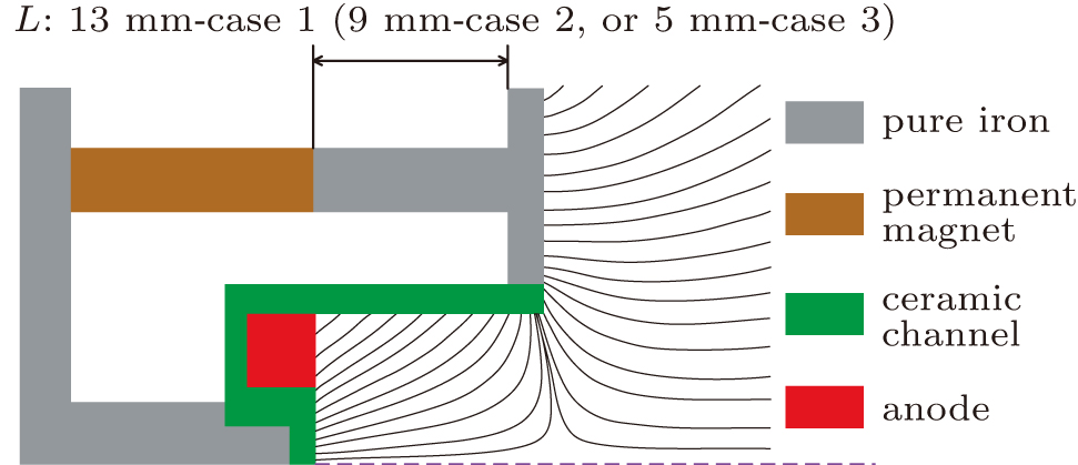
In this paper, the thruster utilizes a permanent magnetic ring to produce magnetic field. Figure
In the 2D-3V axially symmetrical PIC-MCC model employed is the particle-in-cell method combined with Monte-Carlo techniques to simulate the positions, velocities, and energies of the neutral gas, electrons, and ions. This model we developed has been used to study the near-wall conductivity,[14] magnetic mirror effect,[15] and double-stage Hall thruster.[16] The magnetic field is imported from the results calculated by the FEMM software.
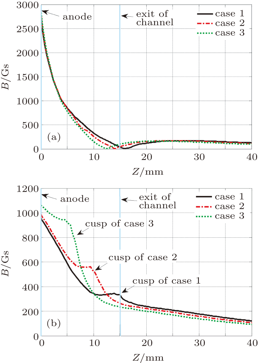
Figure
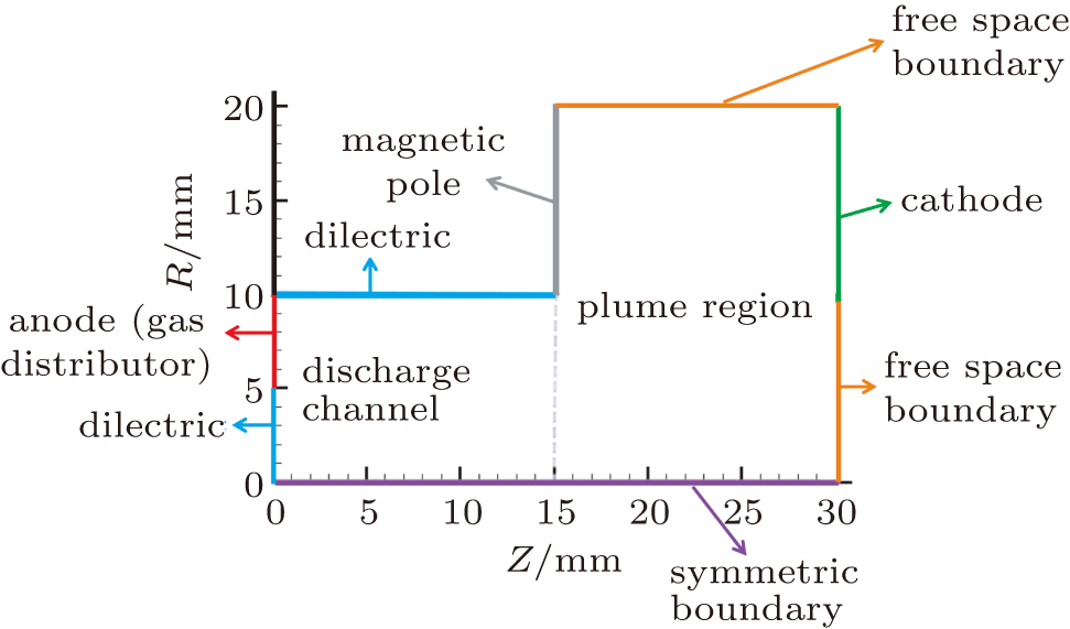
The anode mass flow rate is 0.2 mg/s and the voltage applied to the anode is 250 V. The cathode boundary is at the ground potential, and a quasi-neutrality cathode model is used to inject electrons into the computational domain at a temperature Te = 5 eV. The magnetic pole boundary has a floating potential determined by the net charge collected and a capacitance with a fixed value. When particles hit the metallic boundary (the anode and the magnetic pole), electrons and ions are eliminated. Any particle moving across the free space boundaries would be eliminated. Any particle which crosses the symmetry boundary is specularly reflected.
The electron and ion densities are obtained via the simulation of their trajectories. The Borisʼs leapfrog method is used to study the particle movement. The initial speed of new particles is determined according to the half-Maxwell distribution, and the Poisson equation is solved using the dynamic alternating direct implicit method. The elastic scattering, excitation and single ionization between electron and neutral atoms are modeled by the MCC technique, while the ion-neutral, Coulomb collisions and three-body and radiative recombinations are neglected because of their small collision frequency. At the end of each electron loop, ions are created at the ionization locations. The initial ion velocity is set to be equal to the local neutral background velocity.
Secondary electron emission (SEE) is considered at the dielectric walls. The SEE and electric field models we used at dielectric walls were proposed by Morozov.[17] The electric field at the dielectric surface is 

The time step 


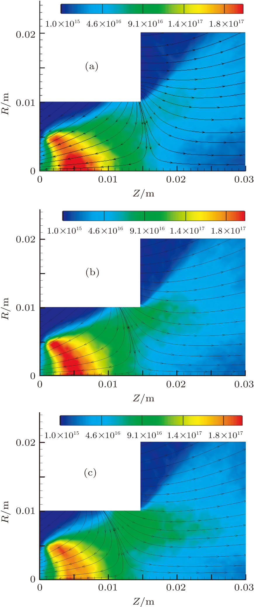
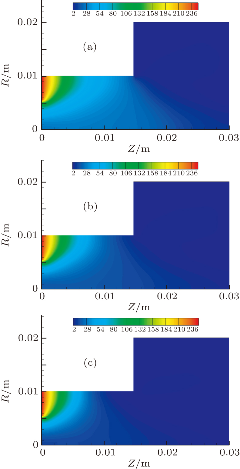
Figure
The simulation results show a clear phenomenon of hollow plume, which accords well with PPPL experimental measurements of the permanent-magnet CHT.[19] It can be explained as follows. The magnetic field in the plume region has a large axial component, resulting in a large radial component of the electric field. Ions which are produced in the main ionization region and the region near the cusp cannot concentrate on the axis under the action of radial electric field.
Figure 


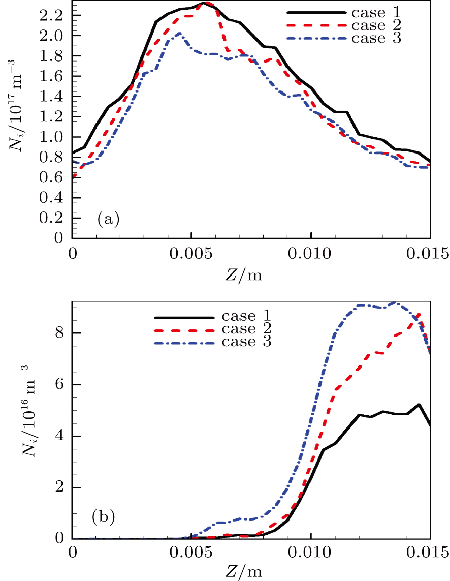 | Fig. 5. (color online) One-dimensional (1D) axial ion density distributions on (a) channel axis and (b) the channel wall. |
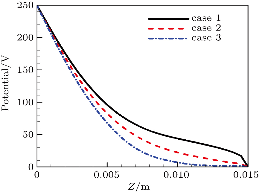
Figure
Figure
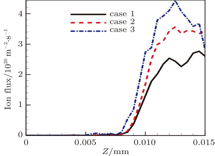
Figure 


In this paper, the effect of the magnetic cusp on discharge characteristics of cylindrical hall thruster is studied by the PIC-MCC method. Special attention is paid to the plasma parameter distribution inside the discharge channel. The simulation results are as follows. The main ionization region and the main potential drop are located at the upstream of the channel. As the magnetic cusp moves toward the anode side, the main potential drop and the main ionization region move upstream correspondingly, and the main ionization process weakens. In this process, the ionization near the cusp is enhanced, increasing the interaction between the plasma and the wall. The simulation results suggest that the magnetic cusp should be located near the exit.
| [1] | |
| [2] | |
| [3] | |
| [4] | |
| [5] | |
| [6] | |
| [7] | |
| [8] | |
| [9] | |
| [10] | |
| [11] | |
| [12] | |
| [13] | |
| [14] | |
| [15] | |
| [16] | |
| [17] | |
| [18] | |
| [19] | |
| [20] |


