Geometrical optics-based ray field tracing method for complex source beam applications
School of Electronic Engineering, University of Electronic Science and Technology of China, Chengdu 611731, China
† Corresponding author. E-mail:
yangf@uestc.edu.cn
1. IntroductionWith the demand for higher data rates and mobility, there has been an unprecedented growth in the development and deployment of wireless communication systems. Understanding radio channel path characteristics is a very important factor for ensuring the quality of service and high data rates for wireless communication systems.[1] Two different approaches are generally used to predict the electric field strength. Empirical models,[2,3] based on the regression of the data gained in measurement, are very fast but not very accurate. Nevertheless, these problems can be avoided by deterministic models. The ray-optical model[4,5] serves as a representative one among them. The ray tracing based on the uniform geometrical theory of diffraction (UTD) is widely used to estimate a site-specific radio propagation for wireless applications.[6,7] When ray tracing is used to calculate the field intensity distribution, each ray will perform the receiving ball algorithm to determine whether the receiver receives the contribution of the ray.[8] Then the total field at the desired observation position can be obtained via the superposition of all contributions from those rays received by the ball. This ray-optical method requires a very large number of GO rays and hence becomes inefficient in many practical applications.
The complex source beam (CSB) idea provides a very efficient tool to estimate the fields radiated by sources. Actually, CSB is a space-time Greenʼs function in complex space. A field excited by any source can then be constructed by CSB.[9] This CSB basis function has a Gaussian-type amplitude distribution and is suitable for replacing the GO ray-optical model in the ray tracing approach because the Gaussian-type distribution tends to yield a more efficient field expansion. Then a new ray tracing method with spectral features of CSB can be used to analyze the wave propagation characteristics of the environment. The CSB basis function provides a solution which maintains the advantages of the GO ray-optical model, and on the other hand, it tends to overcome their shortcomings. Using an additional Gaussian amplitude taper to confine its energy distribution, the CSB modified the traditional GO ray tube to make it wider. The collective treatment of the receiving points uses the CSB formulas which provides field-coverage values at any point in a straightforward manner without reception sphere. Therefore, the CSB is an appropriate candidate for field estimation.
For a complex environment assessment, it often contains a variety of targets. Plane surface meshes have been generally used to represent these complex objects. When a CSB illuminates on a plane interface, the reflected and transmitted fields can be expressed in the form of CSBs by phase matching process.[10,11] For a curved surface, the corresponding curvature information will be totally dropped if the model is discretized with the plane interface. It can be assumed that the radius of the surface curvature is electrically large and varies so slowly that the reflected field may be assumed to be a CSB in the paraxial region and its parameters can be found by complex phase matching of the incident and reflected beams on the surface. This complex phase matching yields a complex reflected caustic distance in complex space, which is similar to the GO caustic distance in real space. While the caustic problem in complex space will not cause the same singularity problem as experienced in GO in the real space.
In this paper, an improved ray model scheme for CSB tracking is presented. Local approximation as a paraboloid in the neighborhood of the reflection point is adopted to represent the curved surface in the environment. The complex phase matching technique provides an efficient way to find the reflected CSB, which is especially useful for tracking a CSB through multiple reflections within the framework of complex ray theory. A new solution for the reflection of a CSB using the conventional right-handed reflected system will be developed in this paper, which can be easily employed in existing computer codes which track a GO ray field, and it is very useful for the multiple reflections.
2. Paraxial CSB and astigmatic GO ray fieldThe CSB concept is utilized to efficiently treat a class of electromagnetic (EM) radiation and scattering problems. The paraxial representation of the CSB, which is given in Ref. [9], is repeated as follows:
As depicted in Ref. [12], the CSB behaves like a rotationally symmetric Gaussian beam (GB) in its paraxial region. A comparison of the source free ray optical GB with the CSB shows that the only difference is that the source free GB does not contain the factor
 , but has a factor of
 . Since CSB (or GB) is just treated as a basis function, weight coefficients
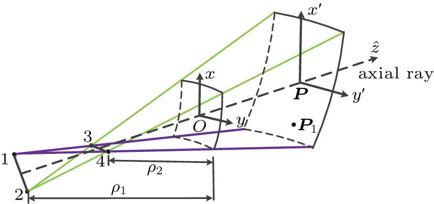
 need adding when dealing with sources as presented in Ref. [9], we can directly use some existing conclusions from the perspective of GB. A z-propagating radiated GB can be obtained by analytically extending the real GO ray field into the complex domain, as depicted in Fig. 1.
Let
 be the electric field at point
 , and it can be expressed as
where

denotes the determinant of matrix

and

. Point

is located on the phasefront centered at point

. The complex phase matrix

is the curvature matrix

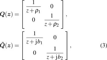
expressed in complex domain, which is defined as follows:
where

and

are the caustic distances (or wavefront radii of curvature) as shown in Fig.
1,

and

are their complex domain forms. If

is a diagonal matrix, the main diagonal elements are the complex principal curvatures, and

is the eigenvector corresponding to the principal complex curvature direction of the beam wavefront. Unlike the applications of GO which are limited to a ray technique associated with possible ray caustics in real space, it is quiet convenient that the complex caustic will not lead to the same singularity problem in complex space. When the complex caustic distances are selected to be equal, i.e.,

, where
b is the beam parameter which is defined as beam collimation distance,
[12] such that
Equation (
4) has a similar form to Eq. (
1), which is especially useful in tracking a CSB through multiple reflections within the framework of complex ray theory.
3. Wave propagation at point of reflectionThe CSB behaves like a rotationally symmetric GB where
 in its paraxial region. Each CSB basis incident electric field which is expanded by sources has a Gaussian-type amplitude distribution and can be expressed as
where

is the coordinate system of the incident beam and

is the complex phase matrix with

and

. When the incident beam is well focused,
b must be large enough such that the most important contribution to the reflection is in the neighborhood of the reflection point, which in general will have the form of an astigmatic Gaussian-type beam. The origin of the coordinate system

here is selected to coincide with the origin of the reflection surface coordinate system such that

denotes the field of incident beam at the point of reflection and

denotes the complex phase matrix at the point of beam reflection. The coordinate transformation between

and the reflection surface coordinates

can be expressed as
Then the reflected field can be expressed as the form of an astigmatic Gaussian beam form
where

is the reflection beam coordinate system and

is the corresponding complex phase

matrix of the reflected beam. It is also convenient to select the origin of the coordinate system

to coincide with the origin of the reflection surface coordinate system such that

denotes the field of reflected beam at the point of reflection and

denotes the complex phase matrix at the point of beam reflection. Then the phase matching approach can be used here to yield the relationship
[11]where
here the superscript T refers to the transpose matrix,

is the angle between the incident beam axis and the normal direction of the surface at the reflection point, and
C0 denotes the curvature matrix at the reflection point on the surface. The local approximation is used to obtain the curvature matrix, and the conventional right-handed reflected system is used to track the field easily, which will be accounted for separately.
3.1. Local approximation of surfaceConsider an arbitrary curved surface, its equation can be expressed as
where
u,
v denote the surface coordinate parameters. In the vicinity of

, the surface can be expanded in a power series form as follows:
where

and

are the first and second order partial derivatives of

,

. We define the unit normal vector

at the point

, it is noted that

, then
If
 is selected to be the origin of the surface coordinate system, the surface can be expressed as
where
with
C0 here determining the curvature matrix at the reflection point on the surface. For convenience, it is assumed that the surface may be locally approximated by a paraboloid in the neighborhood of the reflection point which is given by
where
R1 and
R2 are the local principal radii of curvature of the surface in the
x and
y directions, respectively.
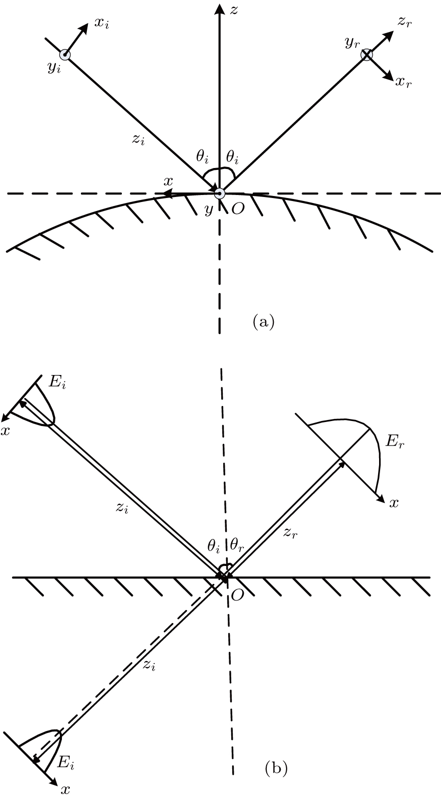
3.2. Simple rule for multi-reflectionsIt is noted that for a well focused CSB, the magnitude of the beam will die out exponentially outside the paraxial region, which implies that the reflected beam is generated primarily by the surface within this region. The complex phase matching technique is presented here to find the reflected beam, which is especially useful in tracking a CSB through multiple reflections. As depicted in Ref. [11], the reflected field can be found via the phase matching method. The reflected coordinate system is chosen to mirror the incident coordinate system at the reflection point such that
 is equivalent to
 . However, the reflected coordinate system will become left-handed, which is contrary to the conventional right-hand rule for a coordinate system, and it is not convenient to track the ray field through multiple reflections. Figure 2(a) shows that the alternative choice for the reflected beam is obtained from
 | |
This choice of
 provides a very efficient means of beam tracking since one can just track the complex phase
 matrix. Since the reflected coordinate system is chosen to be the conventional right-hand rule, it follows that
 is not equal to
 , and it turns out that
 . Then equation (8) can be solved for
 as
as
It is noted that
 can be obtained by CSB expansion, and has been expressed in Section 3. Then one can explicitly determine the elements of the
 as
as
where

may not be a diagonal matrix in general since neither

nor

correspond to the principal complex curvature direction of the reflected beam wavefront. We diagonalize

to find its eigenvalues from
Then the principal direction (or eigenvector) for the reflected beam can be found from
It should be noted that the procedure of diagonalization follows
This equation can be understood as

that can be diagonalized by rotating

into complex coordinate space

. It is very convenient to directly track the beam with the complex phase

matrix, and the reflected field can be easily obtained from Eq. (
7).
By the way, most of the obstacles in the environment have flat structures. As depicted in Fig. 2(b), a beam illuminates on a flat surface, the local principal radii of curvature of the surface R1 and R2 become infinite. While the formula derived above is still true, it is just like an incoming wave emitted from the position of the mirror point of the flat.
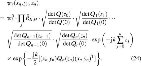
4. Calculation of multi-reflection fieldThe total field is determined via coherent superposition of the individual contributions of each beam. The complex field of the i-th beam at the receiver is given by
It is noted that each reflection needs to change the coordinate system, and the origin of the new coordinate system is located at the intersection point. The
 defined in Eq. (24) is the dyadic planar reflection coefficient which is given by
where
5. Numerical examples and discussionThe purpose of this paper is to provide an improved ray model scheme for CSB tracking. Actual test data are not given here in this paper. However, in order to validate the correctness of the conclusion above, some numerical examples are given in this section. Then the algorithm results are compared with the simulation software, thereby proving the validity of the conclusion.
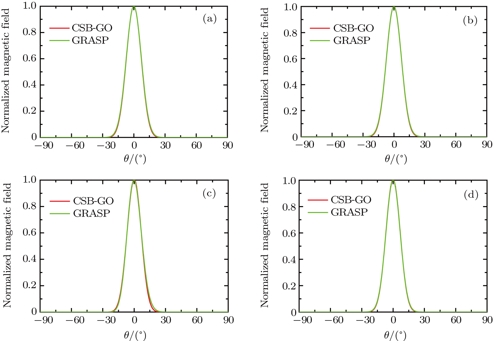
The first case of interest is the reflection of the CSB incident on a parabolic surface as shown in Fig. 3. Here, the CSB axis crosses the reflector surface at points Q1 and Q2 on the surface with the x and y coordinate of (0 m, 0 m) and (0.5 m, 0 m). It is noted that the local principal radii of curvature at these two point are different, and it is suitable to verify that the CSB is transformed into the reflected beam at the reflector surface. The CSB is located at the focus point with parameter b = 5 m, the focal length f = 1 m, and the diameter of the reflector D = 2 m. The simulation frequency is
 . Figure 4 shows the comparison between the reflected field via CSB-GO in Eq. (7) and the General Reflector Antenna Software Package (GRASP) in both φ = 0° and φ = 90° plane at Q1 and Q2 on the surface, respectively, with the radial distance r = 1000 m. It is obtained that these two incidence scenarios are in good agreement.
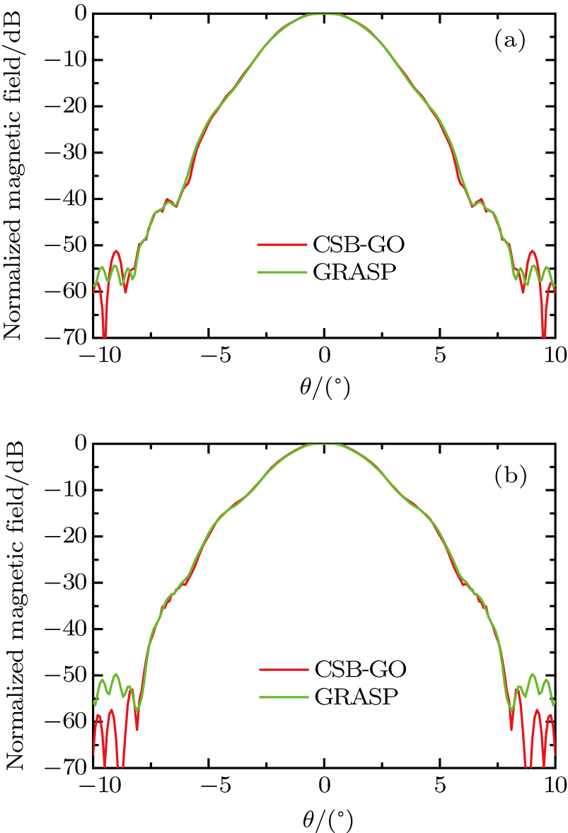
In order to verify the total field of the reflector illuminated by a feed horn given in Ref. [9], the radiation magnetic field of the horn is expanded in terms of CSBs, then the total field is determined via coherent superposition of the individual contributions of each beam with local approximation at each reflection point. The relevant parameters are given in the first case. The feed is located at the focus point and the axis of the horn points to the center of the reflector. The observation point is r = 1000 m in the global coordinate system. The normalized magnetic field in the φ = 0° plane is depicted in Fig. 5(a) and in the φ = 90° plane is described in Fig. 5(b). Due to the co-polarization being much larger than the cross-polarization, only the θ component in the φ = 0° plane, and the φ component in the φ = 90° plane are present. The proposed CSB-GO method and the GRASP in the main lobe region are shown to be in good agreement with each other. Since the proposed CSB-GO method is performed in the paraxial regions, where most of the contribution of the reflection is in the neighborhood of the reflection point, and thus resulting in some differences between these two results outside the main lobe region.
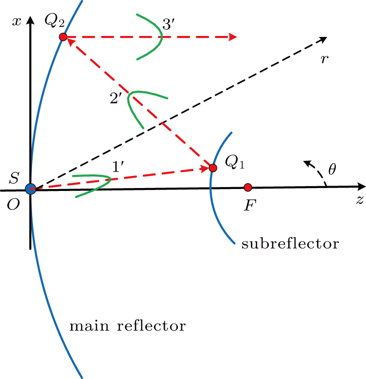
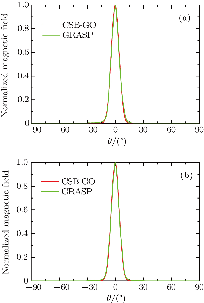
In order to compare with the result of the existing simulation software GRASP, a simple double reflector surface is presented as the last case to verify the multi-reflection condition. The CSB is located at the virtual focus of the subreflector with parameter b = 10 m. The diameter of the main reflector D is 2.4 m, and its focal length is 0.8 m, the diameter of the subreflector d is 0.74 m, and its focal length is 0.4 m. The simulation frequency is 15 GHz. As depicted in Fig. 6, for the CSB emission from the focus, the first reflection happens in the subreflector, then the first reflected beam contacting the main reflector experiences the secondary reflection. Figure 7(a) and 7(b) show the comparisons between the multiply reflected field via CSB-GO in Eq. (7) and the GRASP in both φ = 0° plane and φ = 90° plane, respectively, with the radial distance r = 1000 m. The results obtained from Figs. 7(a) and 7(b) are in good agreement with each other.
6. ConclusionsIn this paper, an improved ray model scheme for the CSB tracking technique is presented. The CSB basis function has a Gaussian-type amplitude distribution and is suitable for replacing a GO ray tube in the ray tracing approach. A complex phase matching technique is adopted to find the reflected beam at the reflection point. Local approximation is used to represent the curved surface near the reflection point. A conventional right-handed reflection system is used to track the field easily. It is a promising method of analyzing the electromagnetic characteristics of the complex environment in the future.


