Power flow analysis in a hybrid phononic crystal structure
Guo Hanbei, Li Qiang, Zhou Liubin, Qiang Lei
The Second Ship-Designing Institute of Wuhan, Wuhan 430064, China


† Corresponding author. E-mail: ghb901127@foxmail.com

Abstract

To reveal the energy transmission through a hybrid phononic crystal structure, power flow analysis is carried out in this paper. Hysteretic damping having significant relationship with power flow is added and corresponding theoretical formulas of the dispersion relation are derived. Besides, the power flow in the hybrid structure is calculated by using the finite element method. The results show that as the damping increases, the boundaries of the band gaps become smoother and dimmer, i.e., broader width. With the increase of damping, the power flow is lowered at the resonance frequencies, while slightly increases near the resonance frequencies. The power flow maps manifest energy distribution in the hybrid structure within and out of the band gaps, which can be exploited in the optimization of the structure design.

1. Introduction

Phononic crystal is a novel kind of artificial periodic structure which shows unique properties to block elastic waves. Several phononic crystal configurations have been constructed, such as mass in mass,[1] parallel masses connected by springs,[2] torsional mass in mass,[3] and so on. Simultaneously, various methods such as plane wave expansion[4] and matrix transfer methods[5] have been developed to calculate the dispersion relation of the elastic waves propagation in phononic crystals. In analysis, the band gaps that are specific frequency ranges within which the elastic waves are dramatically attenuated are the main concern and have potential in the field of noise and vibration control.

There are two main basic mechanisms for the band gaps, Bragg scattering and local resonance. Generally, phononic crystals are just based on one of the mechanisms.[6] Hybrid structures based on both mechanisms are rarely mentioned, let alone the compound characteristics. Zhang[7] presented a hybrid structure by attaching pillars to a plate with periodic holes. A low-frequency band gap was achieved. Krushynska[8] exploited coupled Bragg scattering and local resonance to construct a mechanical metamaterial, and analyzed its band gap performance. Analysis on the hybrid phononic crystals showed good band gap properties. Based on the published literature, a hybrid structure[9] was proposed based on both mechanisms. The dispersion relation was studied by varying the stiffness ratio and mass ratio to optimize the band gaps. To better implement the hybrid structure in practical engineering, further analysis needs to be conducted. Since damping is a factor which cannot be ignored in practical engineering, its influence on the band gaps and wave propagation should be paid attention to. Therefore, a thorough investigation of the hybrid structure with damping is conducted in this paper.

It is well known that power flow analysis is an effective method to describe the energy flow and wave transmission paths in vibrating structures.[10] Pavic[11] studied the effects of structural damping on energy flow and found that the temporal mean value of the total vibratory power input is proportional to the product of the loss factor and the global potential energy. Petrone[12] presented experimental and numerical predictions for power flow in a rectangular plate to reduce the vibration levels. Cho et al.[13] assessed the magnitude and direction of vibration energy flow on dominant transmission paths and the vibratory energy distribution including sink positions by utilizing power flow analysis. However, such a powerful method is rarely used in the analysis of phononic crystals.[14]

In this paper, inheriting the previous study on a hybrid structure,[9] damping effects on the dispersion relation and power flow analysis are both investigated. Theoretical derivation and numerical simulation are presented in Sections 35. Through the analysis, it is expected to provide guidance of design and deeper understanding of the hybrid structure in practical engineering.

2. Band gap property related to hysteretic damping

Figure 1 shows the periodic hybrid structure with corresponding masses and springs adopted in our previous papers.[6] Different from the previous research, the hysteretic damping is considered by changing the stiffness into the complex forms such as , , and . When the harmonic wave propagates in this structure, the equations of motion for the j-th unit cell are

where represents the displacement of the masses in the j-th unit cell with β = 1, 2, 3. The harmonic waveform solution in the j-th unit cell is
where Bβ, q, and ω are the wave amplitude in complex form, the wave number, and the angular frequency, respectively, with β = 1, 2, 3. Periodicity is assumed along the x direction. Based on the Bloch theorem, the harmonic wave solution in the (j+n)-th unit cell for the stationary response is

Fig. 1. (color online) Hybrid structure with complex stiffness.

Substitution of Eqs. (4) and (5) into Eqs. (1)–(3) yields three homogenous equations for B1, B2, and B3, written in the matrix form as

To obtain the non-trivial solution for B1, B2, and B3, the determinant of the coefficient matrix in Eq. (6) is set to 0. The dispersion relation can be determined by solving the polynomial related to the wavenumber and angular frequency. The parameters used in the calculation are presented in Table 1.

Table 1.

Parameters used in the calculation.

.

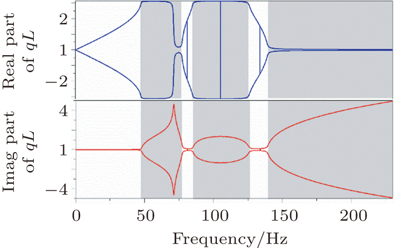
Figures 24 demonstrate the dispersion relations of the hybrid structure with various hysteretic dampings. There are three bands in Fig. 2, and the band structure of the real part of the wave number is consistent with that in Ref. [9]. Three large band gaps can be seen from both the real and imaginary parts of the wave number under the condition of . Also, from the imaginary part of the wave number in Fig. 2, it can be seen there are two different kinds of mechanisms for the band gaps. The band gap covering 48–77 Hz corresponds to the local resonance of the internal spring–mass systems in mass 1. Meanwhile band gaps 83–126 Hz and 135– Hz are attributed to Bragg scattering of periodicity of mass 1 and mass 3. As the damping increases to , the edges of the band gaps become less sharp, which is resulted from the damping dissipation over the whole frequency range. When the damping is , both the real and imaginary parts of the wave number versus frequency tend to be smoother. It is due to large damping forces in the springs that dissipate much energy. Theoretically, it can be understood that out of the band gaps, as the imaginary part of the wavenumber increases, the amplitude of the elastic wave attenuates exponentially. However, for the responses within the band gaps, the damping results in smaller imaginary wavenumber, leading to lowered attenuation.

Fig. 2. (color online) Dispersion relation with damping .
Fig. 3. (color online) Dispersion relation with damping .
Fig. 4. (color online) Dispersion relation with damping .

In the meantime, there exists an asymmetry in Fig. 2, which results from the phase jump of the band structure. The phase jump appears at a specific wavenumber, i.e., the normalized wavenumber equals to π, but when the normalized wavenumber equals to −π, the phase jump cannot be captured. However, when damping is added, for example, in Fig. 3, due to the hysteresis force, the phase jump at the normalized wavenumber of −π is also captured. Therefore, the phase asymmetry in the band structure is due to the phase jumps which can all be captured when the hysteresis force exists.

Through the analysis in this section, we have better understanding of the damping influence on the band gaps, which provides guidance in design of phononics in practical engineering that needs large band gaps to reduce annoying vibrations.

3. Power flow analysis for the hybrid structure

Power flow analysis is a powerful technique to determine the energy flow paths and further provide guidance in structure design. It is first chosen as an alternative method to calculate the stop bands in periodic structures in Ref. [14]. Power flow maps and energy flow among attachments and the main structure show clear vibration paths and help researchers determine the largest energy convergence point. In this work, we want to utilize the useful approach to analyze the power flow in the hybrid phononic crystal structure.

The complex transmitting power can be expressed as follows from the exciting force and structureʼs velocity under a steady-state harmonic analysis:

with being the Hermitian transpose of the force vector. The displacement vector can be calculated from the structural dynamics analysis of the phononic crystal.

A harmonic force is assumed to be applied on a 50-unit-cell system, with motion equation

where the dynamic stiffness matrix can be written as
with
From Eq. (8), the displacement vector can be derived as
From Ref. [14], it is noted that the transmitting power consists of two components with real part representing the active power and imaginary part denoting the reactive power. Usually the active power is calculated to denote the practical energy.

4. Numerical results and discussion

This section aims at solving equations referred to the structural power flow by using finite element method. Therefore, the finite element model of the hybrid structure of 100 unit cells has been established with parameters listed in Table 1. For masses, element MASS 21 is selected with x-direction vibration freedom, while for springs, element COMBIN 14 is chosen with the same vibration direction as that of the masses. The boundary condition for the hybrid structure is that the left end is fixed and the right end is free. At the left end of the model, a harmonic force , is applied on mass 1.

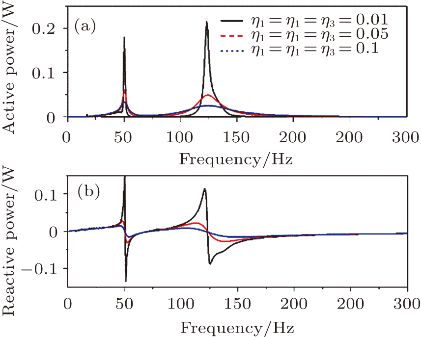
Firstly, the input structural power flow is calculated with damping of η1 = 0.01, η2 = 0.01, and η3 = 0.01, as shown in Fig. 5. The input power flow springs out at specific frequencies. From observation of the response contour, the maximum lies in the resonance of the inner resonance and the complex resonance of the whole structure. Besides, it can be found from Eqs. (7)–(9) that the active power flow is related to the damping matrix and displacement field, which is validated in Fig. 5(a) that the active power flow varies obviously as the damping changes. As we can see, with the increase of the hysteretic damping from 0.01 to 0.1, the active power flow lowers dramatically at the resonance frequencies, but increases near the resonance frequencies. It can be explained by the fact that larger damping results in dramatic response attenuation. Since the attenuation is severer, the product of damping and displacement field is reduced, i.e., the power flow. The reactive part of the power flow also demonstrates the phenomenon.

Fig. 5. (color online) Structural power at the excitation point.

Power flow maps denote the flow direction along the length of one dimensional structures via directional arrows, which simultaneously depict the amplitude of the active power flow.[15] In such a way, consecutive arrows come out from the excitation point and the length of the arrowheads represents the active power flow at different locations. In this paper, the active power flow maps are drawn through a histogram with directions being negative values. The calculation is based on the parameters in Table 1 with damping .

In Fig. 6, the power flow at mass 1, mass 2, and mass 3 is presented at 25 Hz. It is obvious that the power flow at different masses seems identical, which means that at this frequency, energy can propagate through this hybrid structure easily. Zooming in the amplitudes, it can be found that as the distance is further away from the exciting point, the amplitude of the active power reduces to a little. The reduction in power amplitude can be explained by the hysteretic damping from the connecting springs. Furthermore, it should be noticed that the active power has both positive and negative values, which denotes the flow direction with the same positive direction of the x axis.

Fig. 6. Active structural power at 25 Hz at (a) mass 1, (b) mass 2, and (c) mass 3.

Figure 7 demonstrates the power flow in the finite hybrid structure at 50 Hz within the first band gap. It can be seen that active power flow of mass 1 along the one dimension structure is almost average, while for mass 2 around the excitation region, the active power flow is nearly ten times larger than that of mass 1. However, the active power flow of mass 3 is much smaller than that of mass 1 and mass 2. The comparison demonstrates that the structural power is gathered to mass 2 and blocked. In addition, mass 3 seems absent of vibration, so does the power flow.

Fig. 7. Active structural power at 50 Hz at (a) mass 1, (b) mass 2, and (c) mass 3.

In Fig. 8, the power flow at 85 Hz through the hybrid structure is presented. It can be seen that the amplitude of mass 1 is ten times larger than that of mass 2, while the power flow of mass 3 is 3 times larger than that of mass 2. In the meantime, the power flow at mass 1 is uniform as the distance is further away from the exciting point. Yet few energy flows among mass 2 and mass 3. The novel phenomenon depicts that energy is stored or even blocked within mass 1 and mass 3. For practical engineering, a higher strength needs to be applied to resonator 1 and resonator 3.

Fig. 8. Active structural power at 85 Hz at (a) mass 1, (b) mass 2, and (c) mass 3.
5. Conclusion

We analyze the damping effect on the dispersion relation and power flow through a hybrid structure composed of a local resonance and an outer resonance. Theoretical investigation and numerical simulation show that, for band gaps, the damping functions positively, while the attenuation within the band gaps is reduced as the damping increases; for power flow, the product of displacement and damping, it is complicated due to the response dependence on the damping. When small damping is exploited, the responses at resonance frequencies may be maxima, which results in large power flow. As the damping increases, the responses are lowered, so is the power flow. The power flow maps also reveal that within the band gaps, the power flow is dramatically blocked, while out of the band gaps, the power can flow through the hybrid structure like fluid flow. Analysis in this paper provides an alternative mechanism of the hybrid structure which has potential in the field of noise and vibration control.

Reference
[1] Huang H H Sun C T 2009 New J. Phys. 11 013003
[2] Hussein M I Frazier M J 2010 J. Appl. Phys. 108 093506
[3] Wang X 2014 Int. J. Solids Struct. 51 1534
[4] Xiao Y Wen J Wen X 2012 J. Phys. D: Appl. Phys. 45 195401
[5] Liu Y Yu D Li L Zhao H Wen J Wen X 2007 Phys. Lett. 362 344
[6] Zhu X F L S C Xu T Wang T H Cheng J C 2010 Chin. Phys. 19 044301
[7] Zhang Z Han X K 2016 Phys. Lett. 380 3766
[8] Krushynska A O Miniaci M Bosia F Pugno N M 2017 Extreme Mechanics Letters 12 30
[9] Wang T Sheng M P Guo H B 2016 Mod. Phys. Lett. 30 1650116
[10] Alfredsson K S Josefson B L Wilson M A 2015 AIAA J. 34 1250
[11] Pavic G 2005 J. Sound Vib. 281 45
[12] Petrone G De Vendittis M De Rosa S Franco F 2016 Compos. Struct. 140 94
[13] Cho D S Choi T M Kim J H Vladimir N 2016 Thin Wall Struct. 109 1
[14] AlBa’ba’a H B Nouh M 2017 Int. J. Mech. Sci. 122 341
[15] Xu X D Lee H P Wang Y Y Lu C 2004 Thin Wall Struct. 42 979