† Corresponding author. E-mail:
Hydrophobic nanochannel plays a significant role in many physical, biological, and geological phenomena and exhibits impressive applications due to both its ubiquitous distribution and great ability to transport hydrophobic molecules, including various oils and gases. Based on theoretical modeling, we herein reveal that the amphipathic Janus nanoparticles have a large probability to self-assemble into uninterrupted hydrophobic nanochannels inside the aqueous nano-space, although there are large portions of the Janus nanoparticles to be hydrophilic. The key to this observation is the attractions between the hydrophobic regimes on neighboring amphipathic Janus particles through hydrophobic interaction in aqueous nano-space. More surprisingly, the permeation efficiency of hydrophobic molecules through the uninterrupted hydrophobic channel in Janus particles aggregate is even higher than that in the aggregate of hydrophobic particles. We note that the proposed amphipathic Janus particles can be transported to the appropriate positions by the water since the hydrophilic regimes still remain a strong particle–water interaction. We also note that most natural subsurface rocks are not completely hydrophobic or hydrophilic but have complex surfaces with inhomogeneous wetting property. Our work therefore provides a detailed molecular level understanding of the formation of underground strata as well as the new insight for constructing the artificial hydrophobic channels for various applications, such as the design of proppants to enhance the recovery of the unconventional oil/gas.
Hydrophobic nanochannel, which provides an efficient way to transport hydrophobic molecules, plays an essential key role in a plethora of important physical processes ranging from the energy fuel storage,[1,2] nanofluidic channel,[3–5] hydrophobicity-based gating and separation,[6–8] to oil and shale gas exploitation.[9] One of the most direct mechanisms of the hydrophobic channel formation is through the self-assembly[10–13] of hydrophobic nanoparticles in aqueous solutions. However, a solid particle in nature rarely possesses a completely hydrophobic surface. Instead, most of them have a mixed surface with both hydrophobic and hydrophilic regimes.[14] Moreover, in the practical application, due to the weak interaction with water, it is very difficult to insert the hydrophobic nanoparticles into a confined nano-space. For example, in the hydraulic fracturing for the exploitation of oil and shale gas, proppants are widely used to prop the fractures and help the escape of oil/gas under the huge pressure underground. The hydrophilic particles are usually used as proppants since they can be easily inserted into the fractures by the water flow owing to their strong water–particle interaction. It is clear that a hydrophobic channel cannot be formed by those hydrophilic particles. In fact, a big and well-known problem encountered while using these hydrophilic proppants is that, together with water, they usually block the permeation of the hydrophobic oil/gas (which is called water blocking[15]) and thus greatly reduce the oil/gas recovery.[16,17] We note that there are many hydrophobic channels, such as carbon nanotubes,[18] fabricated and studied in the past several decades.[19–26] However, these artificial hydrophobic nanochannels still remain unavailable for many practical applications.
A nanoparticle with an inhomogeneous surface wetting property (so called amphipathic Janus particle[27–29]) may provide a new way to address the challenge. Amphipathic Janus particles have exhibited impressive potential in a wide range of applications, such as controllable pore,[30,31] emulsion polymerization,[32] water-repellent fibers,[33] and colloid surfactant.[34] The aggregating behavior of amphipathic Janus particles in an interface has been studied both theoretically and experimentally.[35–38] In the confined space, very recently, Fernandez et al.[39] theoretically studied the assembly process of the two-dimensional model Janus disks in a confined channel-like environment and received an energetically stable morphology. Little attention, however, has been paid to the formation of the hydrophobic nanochannel aggregated by the amphipathic Janus particles in aqueous nano-space, especially on the behavior of the permeation of hydrophobic molecules through the hydrophobic nanochannel.
We herein show, based on the theoretical modeling, that amphipathic Janus particles have a large probability to self-assemble into an uninterrupted hydrophobic nanochannel in the confined aqueous nano-space. Although the amphipathic Janus particles possess some hydrophilic regimes on the surface, the hydrophobic regimes on neighboring amphipathic Janus particles attract each other through hydrophobic interaction, and therein the uninterrupted hydrophobic channel spontaneously emerges. More surprisingly, the permeation efficiency of hydrophobic molecules through the uninterrupted hydrophobic channel of aggregated Janus particles is even higher than the permeation efficiency through the hydrophobic channel of aggregated hydrophobic particles. The hydrophilic regimes on the Janus particles still have a strong interaction with water so that the particles can be inserted into the nano-space by the water flow. We therefore provide a detailed molecular level understanding of the formation of underground strata due to the amphipathic property of most natural subsurface rock. Furthermore, our work suggests a possible new treatment to construct artificial hydrophobic channels for various applications, including the design of proppants to enhance the recovery of unconventional oil/gas.
Two sets of MD simulations are performed and the details of the simulations are displayed as follows to figure out the self-assembly process of the nanoparticles in confined aqueous nano-space as well as their performance in enhancing hydrophobic molecule flux through a water layer.
The first set of self-assembly simulation systems are performed in the NVT ensemble using Gromacs 4.5.4.[40] GMX forcefield is applied.[41] The common SPC/E water model[42] is used as well. A constant temperature is maintained by the velocity-rescale method with the coupling time of 1 ps. The temperature of the simulation is set to be 300 K. The simulation time is 100 ns with the timestep of 2 fs. The simulation data is collected with the frequency of per 1000 steps. The whole simulation box is set to be 5.200 × 6.000 × 23.191 nm3 accordingly. The periodic boundary condition is applied to all three directions. The long-range electrostatic interaction is calculated by the particle-mesh Ewald (PME) method with a real space cutoff of 1.2 nm. The cutoff distance of the van der Waals (vdW) interaction is 1.2 nm as well. The Lennard–Jones parameters of the carbon atom on methyl (-CH3) and the oxygen on hydroxyl (-OH) are εcc= 0.180 kcal/mol, σcc= 3.786 Å and εoo= 0.203 kcal/mol, σoo= 2.955 Å. The initial velocity is generated according to the Maxwell distribution at the temperature of 300 K. Using the untied atom model, the methyl (-CH3) in our systems is represented by the single C atom according to the parameters in the forcefield.
Many parameters in the second set of simulations keep the same as the first one. However, the whole simulation box is set to be 5.200 × 6.000 × 40.000 nm3, namely, there is enough empty space on the right for gas to diffuse. The methane here is also denoted by the single sphere with the parameters of εcc= 0.302 kcal/mol and σcc= 3.710 Å. The main simulation time is set to be 200 ns with the timestep of 2 fs after the optimization process for 100 ps.
The Molcal package[43] is used to draw the hydrophobic nanochannel among the particle configurations according to the vdW interaction distance of the atoms consisting the nanochannel. The detailed description of this method has been presented (Fig. S3).
Three types of the model amphipathic Janus particles, with the hydrophobic area of nearly 2/3 (pattern-1), 1/2 (pattern-2), and 1/3 (pattern-3) on the surface, are used in our study. The surfaces of the particle are modified using methyl (-CH3) and hydroxyl (-OH) to adjust the local hydrophobicity. Considering the affinity of hydrophilic groups to each other during the preparation,[44] we design the patterns with localized amphipathic regimes on the particle surface (Fig. S1). For comparison, we also prepare the hydrophilic and hydrophobic particles where the surface is completely hydrophilic or hydrophobic.
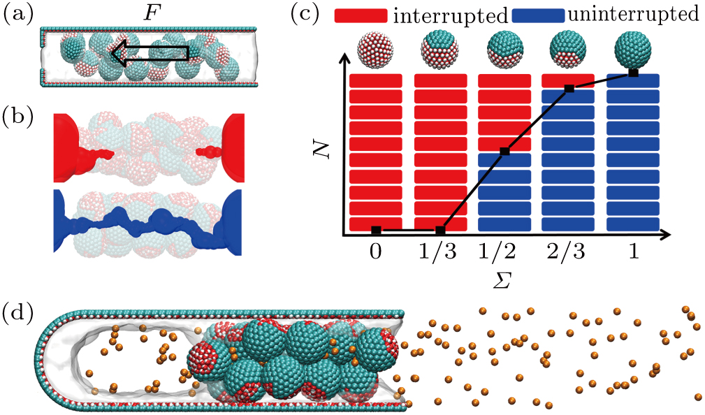
We first study the aggregated configurations of those particles in a nano-size space,[45] which determine the methane permeability since the capillary effect is significant in the micro-pores and water can completely block the hydrophilic fractures. The simulation system is composed of 16 particles soaked in water (Fig. 
For the patterned as well as the fully hydrophobic systems, the hydrophobic regimes of the particles are likely to associate together and generate the tortuous and water-repelling nano-crevice (namely, hydrophobic nanochannel). The typical configurations of the interrupted and uninterrupted hydrophobic nanochannels inside the particle assemblies are presented in Fig.
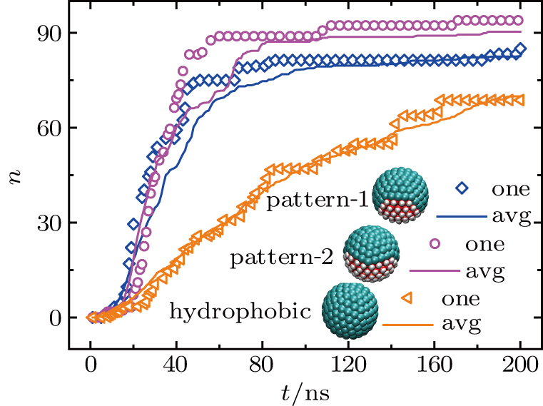
We now study the molecular details of methane permeation through these hydrophobic nanochannels. The aggregated particle configurations obtained from previous simulations are inserted into a tube-like fracture opened at one end. The space between the hydrophilic inner wall of nano-space and the particle assembly is filled with methane molecules, which are separated from the particle assembly by a cubical water body (Fig. S5). The geometry of a typical pattern-1 system at 200 ns is shown in Fig.
To explain the unexpected observations of permeability, we next examine the configuration of the water body in the tube.[46] Within ∼20 ns the initial cubical water bodies in all the systems gradually collapse and reach the converged shapes. This stable stage then lasts till the end of the simulations (see the Appending Movies).
For the typical system with the pattern-1 particles, the water blockage between the methane molecules and the nanoparticle assembly is broken after 20 ns (Fig.
In the complete hydrophobic system, on the other hand, no hydrophilic region exists. Water molecules are only absorbed onto the fracture surface. The water blockage remains intact during the whole simulation. A methane concentration gradient exists in the water body, which drives the permeation of methane gas across the water blockage.[47] After all, methane can still permeate through the complete hydrophobic system, but the permeation is much slower comparing to the patterned systems with uninterrupted hydrophobic nanochannels.
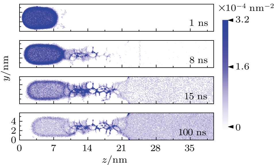
To study the methane diffusion in the confined fracture, we calculate the time dependent spatial density distribution of the methane at four different moments 1 ns, 8 ns, 15 ns, and 100 ns. The normalized density (average over 1 ns) of the methane gas is projected to the yz plane. The density plot for the pattern-1 system is presented in Fig.
At 1 ns, the density of the methane gas in the blocking region from 0 to 8 nm in the z direction is higher than 


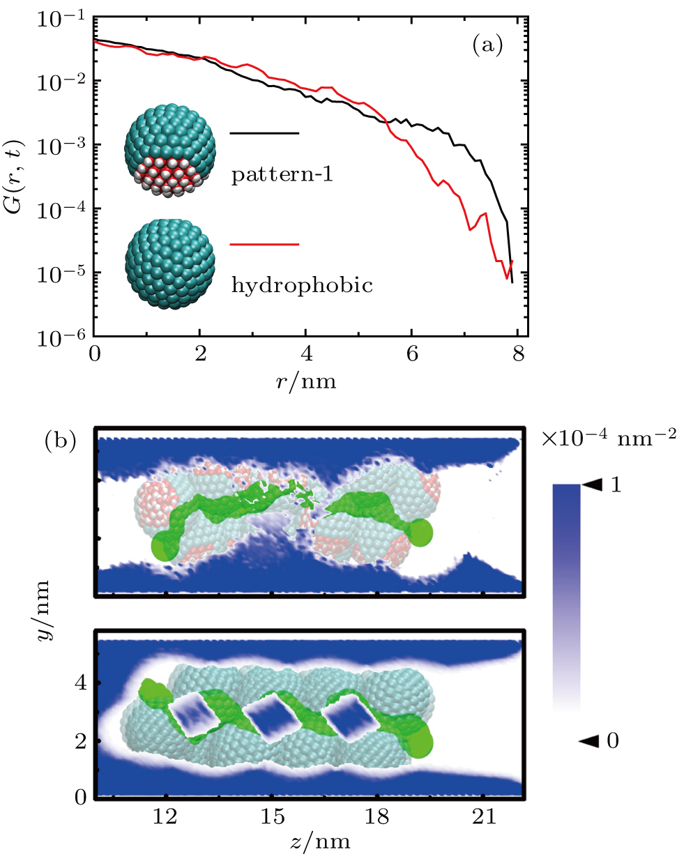
Discussions in the previous sections established that with the same amount of water, certain assemblies formed by amphipathic Janus particles can absorb water into their hydrophilic nano-crevices, which leads to the thinner water blockage and therefore faster methane permeation. In the section, we demonstrate that even after methane molecules pass through the water blockage and reach the hydrophobic nanochannels in the particle assemblies, their permeation is still faster for some of the patterned systems with an uninterrupted nanochannel than the completely hydrophobic one.
The self-diffusion behavior of methane within the particle assemblies is described using van Hove distribution G(r, t).[48,49] This function is defined as the average probability to find a particle at the position r at the time t, given that the particle is located at the origin point at t = 0. G(r, t) of the methane inside the hydrophobic nanochannels along the diffusion direction are calculated for the typical pattern-1 and hydrophobic systems at the time interval of 2 ns (Fig. 
We note that the amphipathic Janus particle is easy to be carried with the fracturing fluid because of the sufficient friction between the particle and water. The moving ability of the particles with the water has a positive relationship with the hydrophilic proportions on each particle surface (Fig. S4).
Based on the theoretical modelling, we show that amphipathic Janus particles have a large probability to self-assemble into an uninterrupted hydrophobic nanochannel inside aqueous nano-space, and the probability has the positive relation with the hydrophobic proportion on each particle surface. Although the amphipathic Janus particles possess some hydrophilic regimes on the surface, the hydrophobic regimes on neighboring amphipathic Janus particles attract each other through hydrophobic interaction, and therein the uninterrupted hydrophobic channel spontaneously emerges. Surprisingly, the permeation efficiency of hydrophobic molecules through the uninterrupted hydrophobic channel of aggregated Janus particles is even higher than the permeation efficiency through the hydrophobic channel of aggregated hydrophobic particles. This is because the aggregated hydrophobic particles only repel and can hardly break the residual water layer in the nano-space, while the Janus particles can tear the residual water layer by adsorbing them on the hydrophilic parts. We note that the hydrophilic regimes on the Janus particles still have a strong interaction with water flow so that the particles can be transported to the appropriate positions by the water. Our work provides a detailed molecule level understanding in the formation of underground strata due to the amphipathic property of most natural subsurface rock, as well as providing new thinking and practical guidance to construct artificial hydrophobic channels for various applications, including the design of proppants to enhance the recovery of unconventional oil/gas.
Detailed structures of five types of model particles, the geometry of the self-assembly simulation system, detailed information of using the Molcal package to draw the hydrophobic pathway in the particle configurations and the results, ability of different particles moving with the water fluid, geometry of methane permeating the simulation system, escaping numbers of the methane in all these 10 sets of simulations with different types of particles and the average results of them, distribution of the methane with the simulation time in pattern-2, pattern-3, hydrophilic, and hydrophobic systems, the van Hove distribution of the methane inside the hydrophobic assemblies in the pattern-1 and hydrophobic systems, comparison of van Hove distributions of the methane inside the hydrophobic pathway with and without water cluster, reason for the water trapped inside the particle assemblies in the hydrophobic system, and self-assemblies of the simple mixture of completely hydrophilic and hydrophobic particles are contained in the Supplementary material.
Supplementary movies are also provided.
| [1] | |
| [2] | |
| [3] | |
| [4] | |
| [5] | |
| [6] | |
| [7] | |
| [8] | |
| [9] | |
| [10] | |
| [11] | |
| [12] | |
| [13] | |
| [14] | |
| [15] | |
| [16] | |
| [17] | |
| [18] | |
| [19] | |
| [20] | |
| [21] | |
| [22] | |
| [23] | |
| [24] | |
| [25] | |
| [26] | |
| [27] | |
| [28] | |
| [29] | |
| [30] | |
| [31] | |
| [32] | |
| [33] | |
| [34] | |
| [35] | |
| [36] | |
| [37] | |
| [38] | |
| [39] | |
| [40] | |
| [41] | |
| [42] | |
| [43] | |
| [44] | |
| [45] | |
| [46] | |
| [47] | |
| [48] | |
| [49] | |
| [50] |


