† Corresponding author. E-mail:
A driver-pickup probe possesses better sensitivity and flexibility due to individual optimization of a coil. It is frequently observed in an eddy current (EC) array probe. In this work, a tilted non-coaxial driver-pickup probe above a multilayered conducting plate is analytically modeled with spatial transformation for eddy current nondestructive evaluation. Basically, the core of the formulation is to obtain the projection of magnetic vector potential (MVP) from the driver coil onto the vector along the tilted pickup coil, which is divided into two key steps. The first step is to make a projection of MVP along the pickup coil onto a horizontal plane, and the second one is to build the relationship between the projected MVP and the MVP along the driver coil. Afterwards, an analytical model for the case of a layered plate is established with the reflection and transmission theory of electromagnetic fields. The calculated values from the resulting model indicate good agreement with those from the finite element model (FEM) and experiments, which validates the developed analytical model.
Eddy current testing (ECT) is extensively used in industries to gauge thickness and conductivity or identify defects for nondestructive evaluation of a part.[1,2] In the simplest case, an ECT probe basically is a coil that receives a magnetic field and generates an alternating excitation field. Nowadays, a driver-pickup probe, consisting of two coils that respectively act as the transmitter and the receiver, has received increasing attention. Such examples can be frequently observed in eddy current array probes.[3,4] Driver-pickup probes have an advantage over one-coil probes in that they have higher gain, wider frequency range, and immunity to thermal drift, because the driver and pickup coil can be individually designed for a specific application.[5] However, a probe sometimes tilts due to surface deformation[3] or poor surface treatment.[6] Basically, eddy current signals are fairly sensitive to probe inclination. The unwanted signal change due to probe tilt is reported to be one of the major obstacles for effective ECT.[6,7] To reduce it, there is a strong demand for powerful, accurate, efficient, and cost-effective tools to investigate the physics.
An analytical model is preferred, because it could establish a mathematical relationship between the signals and the tilt angle of a probe. The signals of a driver-pickup probe are basically the mutual impedance between the driver and pickup coil. Up to date, analytical models of coaxial coils above a layered conductor have been well developed since Dodd and Deeds published their pioneering research results in the late 1960s and the early 1970s.[8] For non-coaxial coils, there are two methods available to deal with the modelling, to the authors’ knowledge. One is to use the Lorentz reciprocity relations,[5,9,10] and the other is to integrate over a receiver according to the definition of mutual impedance, which is easier to implement.[11–13] However, for a tilted driver-pickup probe, the latter method is confronted with difficulties in integrating over the pickup coil. Therefore, the analytical modelling of a tilted driver-pickup probe with the second method is still an open problem.
The main contribution of this paper lies in that spatial transformation is employed to derive the mapped vector of the MVP from the driver coil onto the vector along the tilted pickup coil, thus developing an analytical model of a con-coaxial driver-pickup probe above a layered planar conductor. The remainder of this paper is organized as follows. In Section
In the following analysis, a driver is assumed to carry a sinusoidal signal with the frequency ω, and phasor notation is employed.[10]
We consider two circular filaments as shown in Fig. 
The formulation of MVP for the driver loop has been developed.[14] In the cylindrical coordinate system, there is only the circumferential component 


 |
From Eq. (


 |


According to the triangle exterior angle theorem, α is
 |

 |
 |
 |
The geometry of the tilted loops in free space is shown in Fig. 
According to Eq. (


The projection of 
 |


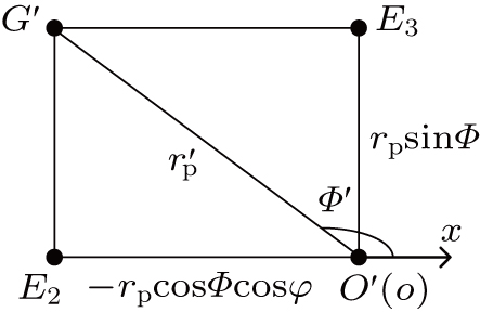
From Figs.
 |
Figure 


 |
 |
The θ is the angle between the vector 

 |
The η is the angle between 

 |
The scalar projection 


 |


We follow the method in SubSection 


 |
 |
Using Eq. (
 |
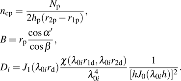
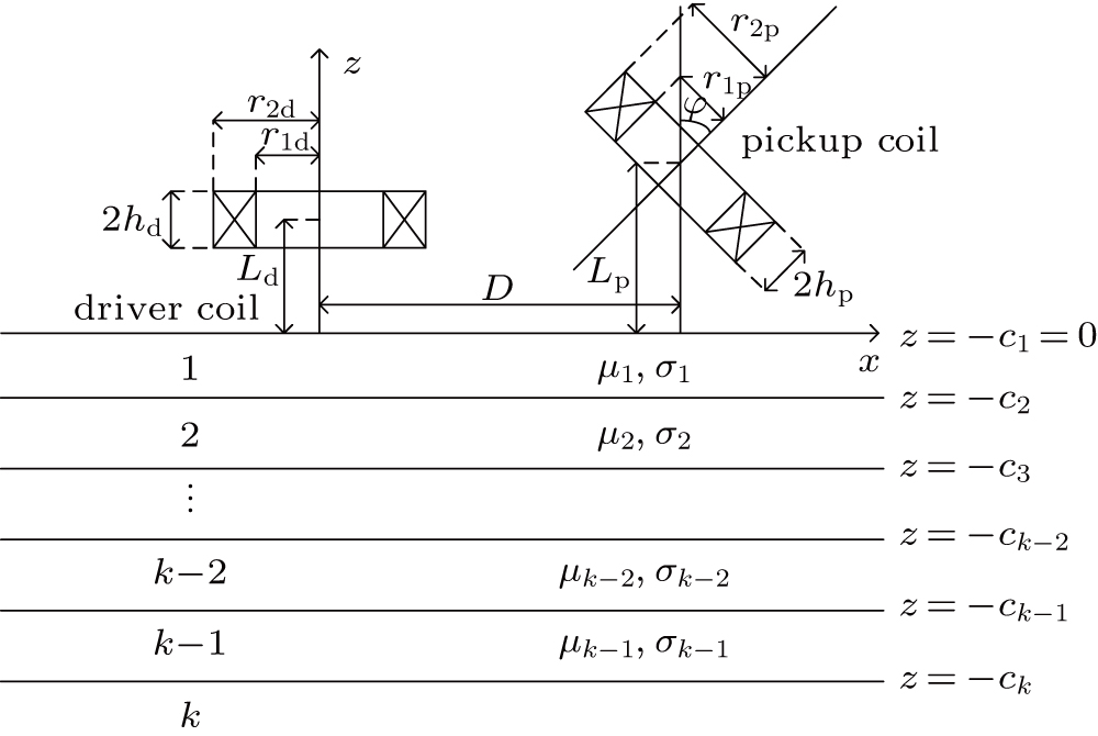
For the eddy current nondestructive evaluation, a coil is of typically multilayer and multi-turn as shown in Fig. 


The total magnetic field above the conductor could be considered as the superposition of the excitation 

 |


 |
 |
 |

 |


 |
 |
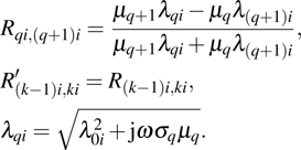
Using the approach of Dodd and Deeds, the discrete nature of the windings is neglected, and the change in mutual impedance can be deduced from Eq. (
 |
Substituting Eq. (
 |
 |
Generally, it is required that the numerical integration should predict the change of mutual impedance. Now we adopt the Gauss–Legendre algorithm to compute the integral in Eq. (
Step 1: Divide equally the intervals 

Step 2: For each subinterval of 

Step 3: Sum the integration results over the subintervals of [0, 2π].
Step 4: Repeat steps 2 and 3 until the integration over the subintervals of [

Finite element model (FEM) is a popular and powerful tool to investigate EC phenomena.[20–22] In this paper, a three-dimensional (3D) FEM for layered structures was developed by using ANSYS Maxwell to implement the simulations. It is noted that the computational burden and accuracy of an FEM are mesh-dependent. Considering the balance between efficiency and accuracy, the maximum length of the elements in the coils was set to be 0.5 mm. For the layered sample, the number of the meshed layers was set to be 5, and the maximum length of the surface triangle elements was set to be 4 mm. The meshed elements would increase by 30% after each iteration. The maximum number of iterations was set to be 20 in order to derive the converged solution of the developed FEM.
The theoretical results presented in Section
| Table 1.
Coil parameters. . |
| Table 2.
Sample parameters. . |
The schematic experimental setup for ECT is shown in Fig.
In experiment, a two-layer case was investigated to validate the developed analytical model. In the case an aluminum plate (P1) and air layer are combined; the frequency of the signal fed into the driver coil increases from 10 Hz to 100 kHz.
Figure
| Table 3.
Circuit parameters. . |
The change in mutual inductance is defined as
 |
Equation (
 |
When the input resistance R1 is on the order of a megaohm, the real and imaginary parts of mutual inductance are given in terms of the magnitude 
 |
In experiment, the driver coil is arranged to be parallel to the sample. Then, the changes in mutual impedances are observed and recorded when the driver coil is titled by angles of 0°, 45°, 60°, and 90° in sequence. Subsequently, simulations are carried out with the formulated analytical model and developed FEM. The experimental and calculated results are shown in Fig.
 | Fig. 14. (color online) Variations of mutual inductance with frequency for (a) φ = 0°, (b) 45°, (c) 60°, and (d) 90°. |
On the whole, the results from the formulated analytical model match well with those from the FEM and experiments. The differences fall within 5%. The good agreement indicates the validation of the presented analytical model. Further analysis suggests that the observed deviations in a low frequency range are less than those in a high frequency range. It is also found that the imaginary parts are superior to the real parts in accuracy.
In the formulated analytical model and FEM, a coil is assumed to be a pure inductor. However, it is reported that an experimental coil has parasitic stray capacitance.[24] Therefore, a disparity basically exists between the calculations and measurements. In addition, the measurement errors also result from coil parameters and tilt angle.
The model is independent of the mesh and offers series-form expression.[25] It presents an efficient and accurate tool to calculate mutual impedance due to a specimen. The developed analytical model can be beneficial to physics-based signal explanation[26] and inverse process to characterize the defects.[10]
In this paper, an analytical model for the change in mutual impedance of a non-coaxial driver-pickup probe due to multilayered conductors is established by using spatial transformation, TREE method and reflection and transmission theory of electromagnetic fields. Instead of utilizing the Lorentz reciprocity relations, this work formulates the induced voltage by integrating over a pickup coil. Such an approach is easy to follow, and the resulting analytical model is simple for numerical implementation.
The presented model enables us to have an in-depth insight into the signal variations due to probe tilt, thus facilitating to find a feature immune to probe tilt. In addition, the developed model could also be used to compute the incident field to improve the efficiency of a forward solver from the volume integral method.
| [1] | |
| [2] | |
| [3] | |
| [4] | |
| [5] | |
| [6] | |
| [7] | |
| [8] | |
| [9] | |
| [10] | |
| [11] | |
| [12] | |
| [13] | |
| [14] | |
| [15] | |
| [16] | |
| [17] | |
| [18] | |
| [19] | |
| [20] | |
| [21] | |
| [22] | |
| [23] | |
| [24] | |
| [25] | |
| [26] |


