Recent progress of colloidal quantum dot based solar cells
Wei Huiyun1, Li Dongmei2, 3, †, Zheng Xinhe1, ‡, Meng Qingbo2, 3
School of Mathematics and Physics, Beijing Key Laboratory for Magneto-Photoelectrical Composite and Interface Science, University of Science and Technology Beijing, Beijing 100083, China
Key Laboratory for Renewable Energy (CAS), Beijing Key Laboratory for New Energy Materials and Devices, Beijing National Laboratory for Condense Matter Physics, Institute of Physics, Chinese Academy of Sciences, Beijing 100190, China
School of Physical Sciences, University of Chinese Academy of Sciences, Beijing 100049, China


† Corresponding author. E-mail: dmli@iphy.ac.cn xinhezheng@ustb.edu.cn

Abstract

Colloidal quantum dot (CQD) solar cells have attracted great interest due to their low cost and superior photo-electric properties. Remarkable improvements in cell performances of both quantum dot sensitized solar cells (QDSCs) and PbX (X = S, Se) based CQD solar cells have been achieved in recent years, and the power conversion efficiencies (PCEs) exceeding 12% were reported so far. In this review, we will focus on the recent progress in CQD solar cells. We firstly summarize the advance of CQD sensitizer materials and the strategies for enhancing carrier collection efficiency in QDSCs, including developing multi-component alloyed CQDs and core-shell structured CQDs, as well as various methods to suppress interfacial carrier recombination. Then, we discuss the device architecture development of PbX CQD based solar cells and surface/interface passivation methods to increase light absorption and carrier extraction efficiencies. Finally, a short summary, challenge, and perspective are given.

1. Introduction

Solar energy as renewable energy has drawn increasing attention, developing high efficiency and low-cost photovoltaic techniques has been regarded as a direct and effective way to solve energy-shortage and environmental pollution problems. Although traditional silicon-based solar cells and Cu(In,Ga)Se2, CdTe thin-film solar cells possess high efficiency and mature manufacturing technologies,[13] it is still tough to further reduce the cost for wide application. Therefore, efforts toward seeking new materials and developing new technologies for low-cost solar cells are ongoing. Currently, some new thin film solar cells are developing rapidly, such as perovskite solar cells (PSCs),[4,5] dye-sensitized solar cells (DSCs),[6,7] organic photovoltaics (OPVs),[8] quantum dot solar cells (QSCs),[911] inorganic–organic hybrid solar cells,[12,13] etc., which are found to be promising for next generation solar cells.

Colloidal quantum dots (CQDs) as potential absorbing materials have been explored for more than 20 years duo to their specific optoelectronic and optical properties. They feature size- and composition-dependent absorption onset, high extinction coefficient, and multiple exciton generation (MEG) effect, especially the MEG effect would lead to incident-photon-to-current efficiencies of over 100%.[1417] Besides, the CQDs allow energy level matching between desired donor and acceptor materials, which is crucial to efficient photovoltaic devices. Therefore, CQD-based solar cells offer the possibility of boosting the PCE beyond the traditional Schockley-Queisser limit of 33%.[18,19] Various device structures have been developed for CQDs based solar cells, including Schottky solar cells, depleted heterojunction solar cells, extremely thin absorber (ETA) solar cells, quantum dot sensitized solar cells (QDSCs), and inorganic–organic heterojunction solar cells. A remarkable progress has been achieved just in the last couple of years by developing more efficient CQDs synthesis techniques, optimizing device architectures, and improving charge transportation. Amongst, QDSCs and PbX (X = S, Se) CQD-based thin film solar cells exhibit better cell performance, and a PCE of 12.34% for QDSCs and a certified PCE of 13.4% for PbS CQD based solar cells have been achieved.[20,21]

Several review articles have been published on quantum dot solar cells. Emin et al. summarized the working principle and the architecture of various CQDs-based solar cells.[22] Yamaguchi et al. focused on various dynamic processes including photo-generation, spatial separation, transfer, and recombination for CQD-sensitized solar cells and CQD heterojunction solar cells.[23] Zhong et al. discussed the QD deposition methods and charge recombination control in QDSCs.[24,25] Sargent et al. summarized the architecture and charge-extraction strategies of CQD solar cells. In this review, advances in QDSCs and PbX based CQD solar cells in the last couple of years will be focused on, including CQD materials and approaches of suppression charge recombination for QDSCs, the progress in device architecture and surface passivation methods of PbX CQD based solar cells.[26,27] Finally, a brief summary, challenge, and prospect will be given.

2. Quantum dot sensitized solar cells

Figure 1(a) shows the schematics of configuration and principle of QDSCs, similar to DSCs. QDSCs usually consist of wide bandgap metal oxide (TiO2, ZnO, and SnO2; the most widely used is TiO2) as photoanode, inorganic semiconductor QD deposited on photoanode as light sensitizer, liquid polysulfide electrolyte and counter electrode (Cu2S, CuS, C, etc.). Briefly, the working principle of QDSCs is as follows: upon light illumination, electron–hole pairs are generated in the QD sensitizer, the photo-excited electrons are injected into the conduction band of the metal oxide, then transport through the metal oxide matrix, the conductive glass, and the external load to arrive at the counter electrode (CE), in the meantime, the oxidized QDs are regenerated by the reduced species (Red) of the electrolyte, finally the oxidized species (Ox) of the redox couple are reduced at the counter electrode to finish one cycle. The device performance is dependent on the charge excitation from QDs, electron injection into TiO2, carrier transport and transfer, which signifies a concerted effort to develop photoanodes, QD sensitizer, electrolytes, and CEs. A remarkable progress for QDSCs has been achieved by the efforts of the researchers in the past few years, especially focused on developing narrower bandgap CQD materials to increase light-harvesting capability, as well as improving charge transportation. Figure 1(b) shows main electron transfer processes occurred at TiO2/QD/electrolyte interfaces, including electron injection and recombination. The interfacial charge recombination will reduce the electron injection efficiency and charge collection efficiency, which may result in low short circuit current ( , low open circuit voltage ( , low fill factor (FF), and poor photoelectric conversion efficiency (PCE). Many strategies have been carried out to suppress the recombination and improve the electron collection efficiency.

Fig. 1. (color online) (a) Architecture and working mechanism of QDSC (FTO: fluorinated tin oxide; VB: valence band; CB: conduction band; Ox: oxidized species; Red: reduced species.[28] (b) Main charge transfer processes occurred at TiO2/QD/electrolyte interfaces including six major recombination paths: (i) recombination between photo-generated electrons in TiO2 and sub-bands (or traps ) in QDs; (ii) recombination between photo-generated electrons in TiO2 and holes in QDs; (iii) recombination between photo-generated electrons in QDs and oxidized species in the electrolyte; (iv) irradiative recombination between electrons and holes in QDs; (v) photo-generated electrons captured by traps; (vi) recombination between photo-generated electrons and oxidized species in the electrolyte.
2.1. CQD materials for QDSCs

There are two ways to sensitize TiO2 photoanode by in-situ and ex-situ methods. In-situ deposition of QDs (CdS, CdSe, PbS, PbSe, etc.) on mesoporous TiO2 film surface mainly can be realized by chemical bath deposition (CBD) or successive ionic layer adsorption and reaction (SILAR) method. This deposition method will lead to high QDs loading, but it is difficult to precisely control the QDs size distribution, therefore, the surface trap state density of the QDs is generally high, which hinders the further development of QDSCs.[2931] In the ex-situ method, the CQDs are synthesized first, then adsorbed on the TiO2 photoanode in the aid of surface linker. For this method, the QDs are size-controlled and high-quality with low surface trap states, but the low QDs surface coverage and low electron collection efficiency caused by organic long chain ligands on the CQD surface will lead to unsatisfactory performance, thus the and PCE are lower than those of QDSCs based on in-situ method. In the last five years, the pre-synthesized QDs deposition method has been significantly improved. Zhong et al. developed a capping ligand-induced self-assembly approach, that is, the pre-synthesized high quality CQDs underwent an ex-situ ligand exchange process to obtain bi-functional molecule linker-capped water-soluble CQDs onto mesoporous TiO2 electrodes. It fact, this approach is a fast and efficient way to obtain 34% QD coverage on the surface of mesoporous TiO2 film, and a series of PCE records of QDSCs were reported, very recently, the highest record PCE of QDSCs of 12.34% was achieved.[21]

Ideal QD sensitizers for QDSCs need to have narrow band gaps, high conduction band edge to ensure enough light absorption, and smooth electron injection from QDs to TiO2. In QDSCs, CdS, CdSe, and CdS/CdSe co-sensitizers are the most studied QDs via in-situ method,[32,33] but their relatively narrow light absorption range limits the and PCE. Meng et al. fabricated various photoanode architectures, and the influences of the structural properties of TiO2 photoanodes on QDSCs have been systematically studied, and high PCEs of 4.61% and 4.92% for CdS/CdSe QDSCs have been reported.[34,35] Tianet al. designed a QDSC with a high efficiency of 6.33% ( , , FF = 0.57) based on Cd0.8Mn0.2Se QDs, and it was demonstrated that the Mn2+ ions doped into QDs can increase the light harvesting, accelerate the electron injection kinetics, and reduce the charge recombination.[36] Wang et al. introduced porous TiO2 nanohybrids as the scattering layer to improve light scattering and QD-loading, and a high of 21.39 mA/cm2 and an efficiency of 7.11% of CdS/CdSe QDSCs were achieved.[37] Cao et al. inserted two ZnSe layers at the interface of TiO2/QD and QD/electrolyte, and the ZnSe buffer layer located at the TiO2/QD interface served as a seed layer to enhance the deposition of CdS/CdSe QDs, while the outer ZnSe layer located at the QD/electrolyte interface behaved as an efficient passivation layer, the resultant device obtained a PCE of 7.24%, which is the highest efficiency for CdS/CdSe QDSCs so far.[38]

PbS or PbSe CQDs have a high absorption coefficient of 1×10⁵–5×105 cm−1 and a wide range of tunable band gaps owning to their large Bohr exciton radius, which is in favor of high ,[3942] and Park et al. have reported an ultrahigh of 38 mA/cm2 by doping Hg2+ into PbS.[43] However, the PCEs of PbS or PbSe based QDSCs are still limited since the slow electron transfer kinetics will lead to inefficient charge separation and collection. In addition, PbS or PbSe QDs may serve as critical recombination centers, thus leading to low . For efficient PbS QDSCs, injection and recombination kinetics of PbS QD have to be adjusted, however, little attempt has been made to date. Therefore, most of the binary QDs based QDSCs present low efficiency due to the limited light harvesting or ineffective photo-excited electron injection.

Developing new CQDs materials with wider photo-response range is one of the most effective ways to further improve QDSCs performance. Ternary or multi-component alloyed CQDs are good choice, which are strongly dependent on the synthetic techniques, such as CuInS2, CdSeTe, CuInSe2, CuInSe1−xSx, Zn–Cu–In–Se, CuInTe2−xSex, etc,[45,4852] as shown in Fig. 2. In comparison to binary QDs, the light absorption edge of multi-component alloyed CQDs can tuned by controlling their composition and sizes, however, their bandgap may be narrower than their binary constituents due to an optical bowing effect, the absorption edge of almost all above mentioned alloyed QDs can extend to the near-infrared (NIR) region, which are more attractive sensitizers for QDSCs.[53,54] Meng et al. have successful prepared CuInS2 and CdSeTe alloyed CQDs by solvothermal synthetic method and aqueous synthesis,[5558] the as-prepared mercaptoacetic acid (TGA) capped CuInS2 CQDs can be uniformly dispersed for a long time, and CdSeTe based QDSCs with a certified PCE of 11.3% have also been assembled, which achieve one of the highest efficiency at the moment.[59] Very recently, Zhong et al. reported Zn–Cu–In–Se CQDs based QDSCs with a high PCE over 12%.[10]

Fig. 2. (color online) Highly efficient QDSCs based on alloyed CQDs. (a) Schematic energy level diagram and corresponding device performances of CdSe, CdS, and CdSeTe CQDs.[44] (b) Schematic of CuInTe2−xSex CQD and EQE curve of the corresponding CuInTe2−xSex based QDSCs.[45] (c) JV curves of CuInS2-Zn and CuInS2-based champion cells.[46] (d) The champion device based on Zn–Cu–In–Se alloyed CQDs with a certified PCE of 11.61%.[47]

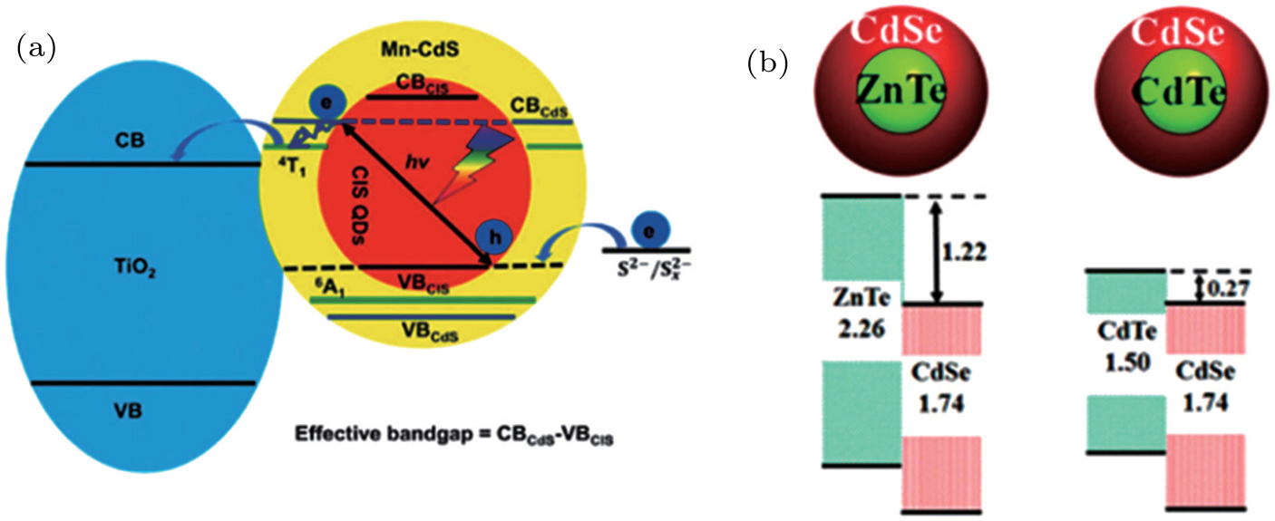
Besides, type-II core-shell CQDs can also extend the spectral response range due to narrower effective band gap; meanwhile, the type-II level structure is beneficial to spatial separation of electrons and holes, thus prolonging excited-state lifetimes. This is crucial to multi-excition generation and efficient QDSCs.[61] Type-II core-shell CQDs can be obtained in either aqueous or organic systems. Much recent research efforts have been devoted to preparation of various type-II core-shell CQD structures, like CdSe/ZnSe, CdTe/CdSe,[62] ZnTe/CdSe, ZnSe/CdS, CuInS2/CdS,[63] etc. As shown in Fig. 3(a), Meng et al. developed a simple preparation in an aqueous system for CuInS2 CQDs and Mn-CdS shell via SILAR method in sequence, the CuInS2/Mn-CdS core-shell CQDs formed type-II alignment and the absorption edge has been extended up to 800 nm, much longer than that of single CuInS2 or Mn-CdS QDs, and the corresponding cell presented a of 19.29 mA/cm2 and a PCE of 5.38%.[56] Zhong et al. synthesized CdTe/CdSe and ZnTe/CdSe core-shell CQDs with absorption onset wavelength of 850 nm in an organic system successively (Fig. 2(b)),[60,64] the resultant ZnTe/CdSe QDSCs exhibited a certified efficiency of 6.82% due to a faster electron injection rate.

Fig. 3. (color online) (a) Core-shell CuInS2/Mn-CdS CQD based QDSCs.[56] (b) Highly efficient ZnTe/CdSe and CdTe/CdSe type-II core-shell CQD based QDSCs.[60]
2.2. CQDs based QDSCs

Recently, QDSCs have experienced rapid development, and the cell efficiency has been significantly improved from 5% in 2012 to current 12%. In fact, the preparation of high quality CQDs and development of a capping ligand-induced self-assembly approach have made a tremendous contribution, which gradually show great advantages over the in-situ deposition method (SILAR and CBD). Sharp excitonic absorption peak and relatively high photoluminescence (PL) intensity are usually observed in high-quality CQDs, indicating its low non-radiative recombination rate, high crystallinity, and low trap state density. However, such a distinct feature cannot be achieved by SILAR or CBD deposition methods. Moreover, for highly efficient QDSCs, effective suppression toward charge recombination and selection of superb counter electrode materials are also important.

Currently, the PCEs of QDSCs are still unsatisfied in comparison to those of PSCs and the theoretical efficiency of 44%, which are often attributed to QD surface states or back electron transfer at the solid–liquid interface. The surface traps sometimes called trap states may interfere with electrons injected from QDs to TiO2. Passivation of surface states is often adopted by molecular modification or deposition of another semiconductor material, which is usually realized by a solution process. ZnS as the passivation layer by SILAR method has already been a routine procedure to prepare QDSCs. It is demonstrated that ZnS passivation can enhance the charge injection efficiency largely by reducing carrier trapping and recombination in QDs, and play an important role in the stability and the cell efficiency: (i) to prevent the QDs photocorrosion in the electrolyte and improve the device stability; (ii) to prevent reverse electron transfer from TiO2 to electrolyte and increase charge efficiency; (iii) to reduce surface trap states of QDs and thus increasing electron injection efficiency. Furthermore, ZnSe is found to be another efficient passivation material to replace ZnS. Wang et al. suggested that ZnSe may be a more efficient passivation layer than ZnS, which was attributed to a type II energy band alignment between CdS/CdSe QDs (core) and ZnSe layer (shell), leading to more efficient electron–hole separation and slower electron recombination.[65] Besides, wide bandgap metal oxide materials, such as MgO, ZrO2, SiO2, and Al2O3 deposited on TiO2/QDs surface can also be used as energy barriers to prevent the recombination between photogenerated electrons in TiO2 and holes in the electrolyte. Atomic layer deposition (ALD) technology is one of the most reliable ways to prepare passivation layer due to its conformal coating, high purity, and molecular-level control in thickness and composition.[6668]

Furthermore, the post-treatment method is adopted to passivate defects and suppress the recombination. Zhong et al. employed a ZnS/SiO2 double layer onto TiO2/QDs surface through SILAR (ZnS) and hydrolysis (SiO2) processes in sequence, interfacial recombination was remarkably inhibited with higher , and a certified PCE of 8.21% for QDSCs, and the device stability was also improved.[70] An amorphous TiO2 buffer layer was further inserted between TiO2/QDs and ZnS/SiO2 layer via a TiCl4 hydrolysis, exhibiting a certified PCE of 9.01%.[69] Very recently, the same method was applied to Zn–Cu–In–Se based QDSCs with a record PCE of 11.6%.[45] Passivation toward interfacial recombination is viable by introducing some additives in polysulfide electrolyte. Meng et al. introduced fumed SiO2 nanoparticles (NPs) into polysulfide electrolyte to improve TiO2/CdSeTe/electrolyte interfaces for the first time.[58] The and FF were significantly enhanced with a certified PCE of 11.3% achieved, which is one of the highest PCEs among current QDSCs. In addition, a gel electrolyte was also obtained after adding SiO2NPs, thus leading to better device stability. Recently, Zhong et al. reported various electrolyte additives to suppress charge recombination, including tetraethyl orthosilicate (TEO),[21] poly(vinyl pyrrolidone) (PVP),[71] and polyethylene glycol (PEG),[72] thus the and PCE of QDSCs were improved, and a PCE over 12% was achieved based on the TEO modified electrolyte. Obviously, the modified electrolyte turns out to be a simple and effective approach to improve the cell performance, thus it is still necessary to explore more potential additives.

Fig. 4. (color online) (a) A modified passivation method toward the photoanode by using an amorphous TiO2 (am-TiO2)/ZnS/SiO2 barrier layer, and (b) CdSeTe QDSCs based on this passivation method exhibit a PCE of 9.28%.[69]
Fig. 5. (color online) CdSeTe QDSCs based on fumed silica (SiO2) modified polysulfide electrolyte achieved a certified PCE of 11.3% and better stability. PEG: polyethylene glycol.[58]

As we know, the of QDSCs is generally below 0.65 V, which greatly limits the cell efficiency. Therefore, further improvement on the is critical to promote the development of QDSCs. Except for using passivation layer, developing more efficient counter electrode (CE) has been proved as an important path. As an important component in QDSCs, CE collects electrons from external circuit and transfers them to electrolyte through catalytic reduction of oxidized species in the electrolyte.[73] An ideal CE needs to possess high electrical conductivity and good catalytic activity. Currently, Cu2S based CE is one of the most effective CEs, however, it is usually based on brass sheet, which is unstable in the polysulfide electrolyte. In the past five years, developing new CE materials has brought enormous improvement in . Meng et al. have made lots of efforts on CEs, and the highly electro-catalytic and stable PbS/carbon and Cu2S/carbon composite CEs have been prepared using a low cost, low-temperature method, which show low charge transfer resistance.[74,75] They firstly employed CuInS2 as the CE for CdS/CdSe QDSCs, and modified electron transfer activity and device stability were achieved by further combining carbon/CB mixture, leading to a PCE of 4.32% in 2013.[76] Besides, they developed a new in-situ method to prepare CuS CE, and this kind of CuS CE exhibited good interfacial electron transfer property and electro-catalytic activity, up to 4.59% of PCE was achieved for CdS/CdSe QDSCs.[77] Kamaja et al. synthesized a MoS2-CuS composite CE, and the MoS2 sheets increased electron-transfer ability and catalytic activity, leading to low charge-transfer resistance.[78] Ghosh et al. synthesized a composite CE consisting of Cu1.8S nanoplates and graphene oxide nanoribbons, which led to a high PCE of 6.81% for CdTe/CdS/CdS QDSCs.[79] Zhong et al. reported a series of efficient carbon based CEs. For example, they developed graphene hydrogel (GH) based CEs for CdSeTe QDSCs which exhibited a PCE of 9.85% and a of 0.756 V, as shown in Fig. 6(a), further introducing CuS NPs to GH CEs, the values of PCE and were further improved to 10.71% and 0.786 V, respectively (Fig. 6(b)), which could be attributed to the good conductivity of GH and high catalytic activity of CuS.[80] In addition, Ti mesh supported mesoporous carbons (MCs) as CEs for QDSCs showed high catalytic capacity, good conductivity, and also lowered the redox potential of the polysulfide electrolyte for higher , which gave a certified PCE of 11.16% with an ultrahigh of 0.798 V. Nitrogen-doped mesoporous carbons (N-MCs) supported on Ti mesh were further employed as CEs for Zn–Cu–In–Se QDSCs, exhibiting a certified PCE up to 12.07% with of 0.765 V. Therefore, exploiting new CE structure and materials suggests a path forward for improving QDSCs performance.

Fig. 6. (color online) (a) FESEM image of graphene hydrogels (GHs)-CuS hybrid. (b) Fabrication of GH-CuS CE and the cell performance of CdSeTe QDSCs with various CEs.[80]
Table 1.

Some advances in highly efficient QDSCs in the past few years.

.
Table 2.

Some advances of PbX CQDs based solar cells in the past five years.

.
3. PbX (X = S, Se) based colloidal quantum dot solar cells

PbX (X = S, Se) CQDs possess tunable near-infrared absorption, multiple exciton generation effect, and solution-processed ability, which have emerged as attractive candidates for thin film photovoltaics.[88] PbS and PbSe CQDs are the most common types of CQD materials used in quantum dot thin film solar cells, which possess narrow bulk bandgaps of 0.41 eV and 0.27 eV, respectively, making them ideal candidates for tuning the absorption spectra in the near-IR range of the sun’s spectrum.[89] Hot-injection method has been employed to prepare PbS or PbSe CQDs, that is, S or Se precursor solution is injected into Pb precursor solution, and precursor decomposition and rapid nucleation processes are typically involved. The most common precursors for PbS and PbSe syntheses are lead oxide (PbO), oleic acid, and bis(trimethylsilyl)sulfide ((TMS)2S) or bis(trimethylsilyl)selenide ((TMS)2Se).[90,91] CQD sizes can be controlled by varying the injection temperature, precursor concentration, conversion rate, and saturation degree, the excitonic peaks are in the range of 880–1600 nm, corresponding to CQD diameters of 3–6.5 nm.[92]

However, the benefits of the tunability and processability of CQDs are counter-balanced by the challenge of achieving superior device performance. In the meantime, high light absorption and charge collection efficiencies are two major requirements to increase the solar cell efficiency. Progress in device architecture as well as advances in managing CQDs surface chemistry have recently led to significant improvement on PbX CQDs based solar cells and the best certified PCE of 13.4% has been achieved.[20] Here, recent progress of PbX CQDs solar cell performance mainly on device architecture engineering, surface chemistry programming, and structured electrodes to improve carrier collection, especially the significant advances in CQD surface passivation, will be reviewed.

3.1. Device architecture engineering for PbX CQDs based solar cells

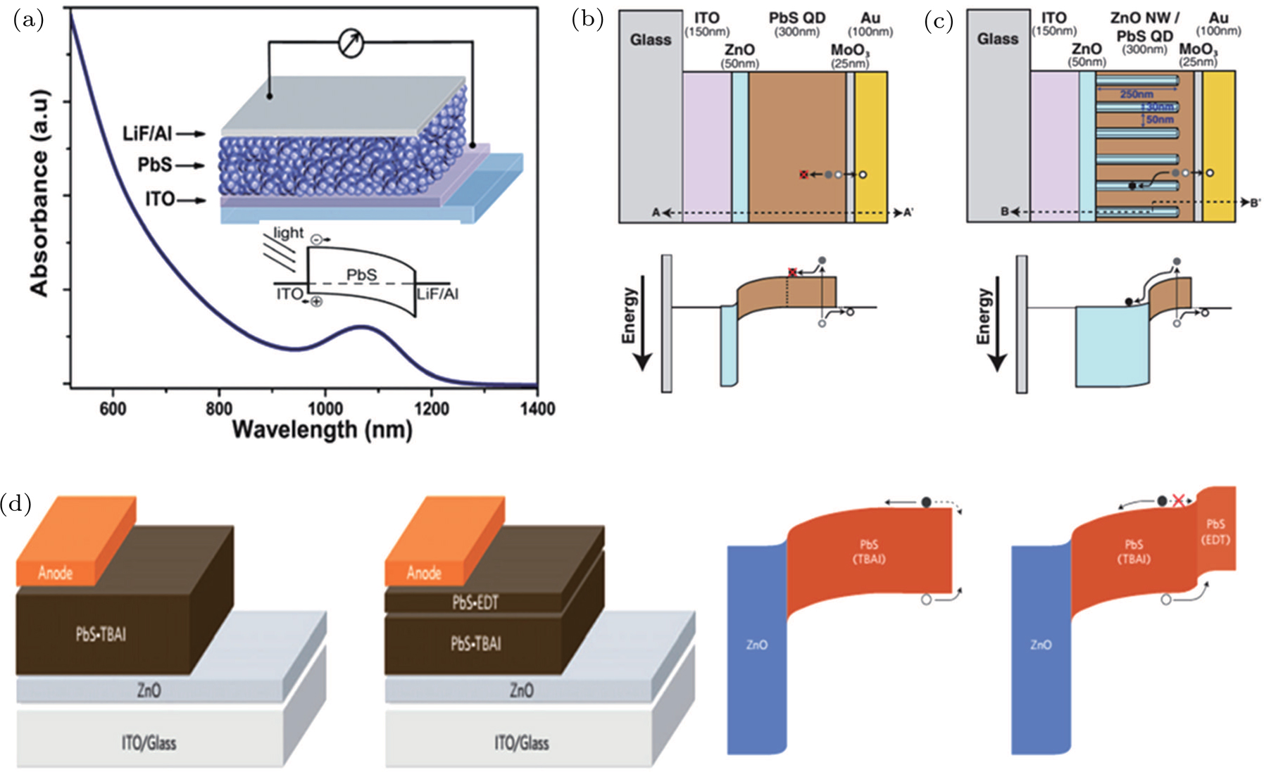
As shown in Fig. 7, the device architecture progresses from Schottky junction to depleted heterojunction, bulk heterojunction, and quantum junction, and in this process, significant improvement on charge extraction has also been achieved.

Fig. 7. (color online) The evolution progress of CQD solar cell architectures. (a) The schematic of Schottky CQD solar cell structure and diagram of energy levels.[93] The schematics and energy band diagrams of (b) planar depleted heterojunction solar cell and (c) bulk heterojunction solar cell.[94] (d) Device architectures and energy bending in ZnO/PbS-TBAI and ZnO/PbS-TBAI/PbS-EDT devices at short-circuit conditions.[95]
3.1.1. Schottky solar cells

In early research stage of CQD based solar cells, a Schottky structure was employed, as shown in Fig. 7(a), wherein a p-type CQDs absorber was sandwiched between a transparent conductive oxide and a shallow-work-function electrode (Al, Ca, Mg). A Schottky barrier is formed at the junction between the PbS CQD film and the metal electrode, where the photon-generated carrier separation and transport occur.[96,97] This Schottky architecture shows several advantages, including less interfaces and ease of fabrication. Efforts on the performance improvement of Schottky solar cells mainly focus on optimizing metal species, developing ligand strategies, and extending the response into the infrared range.[98102] Ternary PbSxSe1−x CQDs were used in Schottky solar cells and showed better and than PbS or PbSe CQDs.[100] Choi et al. tailored the PbS CQD/metal interface by introducing an ultrathin oxidized interfacial layer to improve the quality of the Schottky barrier and the device performance.[103] Besides, an inverted Schottky CQD solar cell was also constructed, wherein a PbS CQD film was sandwiched by a low work function transparent conducting oxide and a high-work-function metal anode, and the champion device was obtained with a PCE of 3.8% and a record of 0.75 V.[104] Despite of these advantages, the Schottky architecture suffers some limitations. Firstly, some minority carriers have to travel the entire film before reaching the destination electrode, thus leading to strong recombination. Secondly, the is generally limited by the Fermi level pinned at the metal/CQD interface. The introduction of buffer layers and other methods to reduce the density of electronic trap states at the interface can diminish this problem slightly. Moreover, the Schottky structure also requires the light illumination from the non-rectifying side of the junction, which is a problem for transport-limited CQD films.

3.1.2. Heterojunction CQD solar cells

In 2010, planar depleted heterojunction CQD solar cells were developed to overcome the limitation of Schottky solar cells by permitting somewhat thicker active layers and moving the depletion layer to the front contact to suppress recombination losses.[105] Figure 7(b) shows a typical device architecture, consisting of a CQDs layer sandwiched between an n-type wide-band-gap semiconductor (usually TiO2) and the metal electrode. In this device, electrons flow toward the TiO2 rather than the metal electrode, thus creating an inverted polarity, in the meantime, the hole transfer from TiO2 to CQDs is prohibited which can promote efficient carrier separation. In comparison with Schottky solar cells, this heterojunction architecture has following advantages: firstly, more efficient carrier separation benefits from the built-in field of the depletion region; secondly, relatively high open-circuit voltages can be obtained due to better carrier separation at the CQDs/TiO2 interface.[106] An optimized device structure must balance the competing demands between light absorption and charge carrier collection, and an active layer thickness of is normally required to absorb 90% of incident photons at the band gap of CQDs.[107] However, only photo-generated carriers within one diffusion length of the depletion region are efficiently collected, thus the thickness of the CQD film is limited. The carrier diffusion length in the CQD film is reported to be in the range of 10–100 nm.[108,109] In order to retain efficient charge extraction, the thickness of the active CQD film cannot exceed the sum of carrier diffusion length and depletion length. The optimal thickness of the PbS CQD layer is about ∼300 nm, which is insufficient for light absorbance, thus leading to a low . Ligand strategy has been demonstrated as a promising approach to passivate the CQD surfaces and increase the diffusion length of charge carriers so that charges can be collected from thicker active layers. 3-mercaptopropionic acid (MPA) has been used to passivate PbS CQD surfaces, leading to reduced defect density and greater mobility,[105] and an enhanced PCE of 5.1% for depleted heterojunction solar cells has been achieved in 2010.[110]

Bulk depleted heterojunction architectures suggest a path forward for further improving the cell performance. As shown in Fig. 7(c), ordered or random nanostructured metal oxide electrodes are interpenetrated with CQDs, which thus allows the extension of the depletion region and improves the optical absorption, charge separation, and collection efficiency, resulting in remarkably enhanced . However, the above architectures also introduce more interfaces and more interfacial recombination, thus leading to lower than that of planar depleted heterojunction CQD solar cells. Tailoring the CQD/metal oxide interface by inserting an additional window layer or passivating the junction with doped polymers has been demonstrated to be the key to reduce carrier recombination and improve electron extraction.[112,113] Zhao et al. introduced a CdI2-treated CdSe QD buffer layer between ZnO and PbS CQDs to optimize the band alignment and passivate the interface traps, leading to an improved PCE of 7.5%.[114] Wu et al. found that the PbS CQD film morphology and the device performance were highly dependent on the solvent, and a mixed n-octane/isooctane solvent was suggested to promote the cell performance with a PCE of 7.64%.[115] Yuan et al. employed an ultrathin n-doped [6, 6]-phenyl-61-butyric acid methyl ester (PCBM) as the buffer layer between TiO2 electrode and PbS-TBAI CQDs layer, as shown in Fig. 8. It was demonstrated that apart from passivating the interface traps, this n-doped PCBM widened the depletion region in the CQD layer, resulting in enhanced electron injection from PbS to TiO2 electrode, and a high PCE of 8.9% was achieved with improved and FF.[111]

Fig. 8. (color online) The introduction of n-PCBM buffer layer leads to enhanced device performance. The black lines represent the control device, and the red lines represent the n-PCBM modified device.[111]
3.1.3. Quantum junction CQD solar cell

From Schottky to heterojunction solar cells, the device performance has experienced a rapid improvement, and the remarkable improvement of PCE has been achieved in less than a decade. Notably, prior solar cells employed p-type CQDs absorber and n-type electrode (such as TiO2) to form a rectifying junction and efficient photovoltaic devices.[110] Current depleted-heterojunction solar cells rely on careful tailoring toward the band offset between p-type CQDs and TiO2 electrode. In contrast, quantum homo-junction can overcome this drawback wherein p-type CQDs and n-type CQDs are employed, as shown in Fig. 9,[117] which enable both sides of the junction being quantum-tuned.[118] The difficulty in quantum junction lies in preparing air-stable n-type CQDs (electron-rich) since they are prone to be oxidized within minutes of air exposure. Careful engineering toward the CQD surface and developing complete ligand shell have been demonstrated as an efficient path to solve this problem. It is found that n-type PbS CQDs can be achieved by using atomic passivation, wherein inorganic halide anions exhibit n-type doping character in CQD solids, and small steric hindrance to a complete coverage of CQD surfaces, thus can protect against oxidative attack. From Fig. 10, it can be seen that both carrier density and carrier mobility strongly depend on the species of halogen. Iodide passivated films possess the highest carrier mobility and the lowest doping density, which allows better carrier collection and greater depletion of active absorbing layer, thus iodide can be considered as the most advantageous halide treatment for photovoltaics.[119,120]

Fig. 9. (color online) (a) The structure and energy band alignment diagrams of quantum junction and depleted heterojunction. (b) The simulated device performance ( , , PCE) of quantum junction CQD solar cell and depleted heterojunction CQD solar cell.[116]
Fig. 10. (color online) Comparison of iodide-, chloride-, and bromide-treated CQD solids and corresponding devices. (a) Three devices performance tested in air; EQE of iodide (b) and bromide (c) solid-state ligand-exchanged devices observed before and after air exposure; (d) Fermi level ( , valence band ( , and conduction band level ( of CQD films with different halide treatments; (e) the amounts of oxidized species in CQD films with different halide treatments.[123]

It is demonstrated that increasing doping concentration in PbS-EDT layer can shift the distribution of the depletion region towards the PbS-TBAI layer, allowing for higher carrier mobility and more efficient charge extraction. For example, NaHS was used to treat PbS-EDT layer, leading to threefold increase and thus enhanced and FF.[121] Kim et al. firstly reported the modification to ZnO/CQDs interface with self-assembled monolayers (SAMs), which can help withstand the damaging effects of the CQD film during ligand exchange processing and tailor the band alignment at the ZnO/PbS CQD interface, leading to a record PCE of 10.7% due to enhanced and FF.[122]

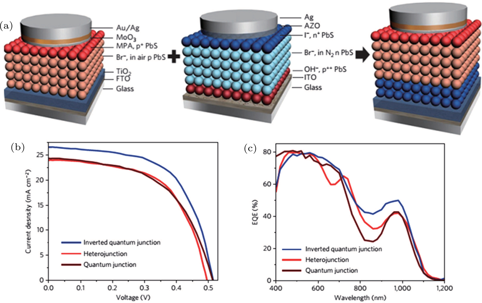
The halide treatment has promoted the CQD photovoltaics development in the past few years. Ning et al. successfully obtained air-stable n-type PbS CQDs based on iodide ligands, whose electronic properties can be controlled by the halide doping density.[124] A graded-doping structure was further constructed, which presented a higher due to enhanced built-in voltage and carrier collection.[124] They further built an air-processed inverted quantum junction device (Fig. 11), and this device showed a record of 26.6 mA/cm2 and a PCE of 8%.[123] Jin et al. employed graphdiyne as anode buffer in quantum junction CQD solar cells, which prolonged carrier lifetime and reduced surface recombination, and the PCE was notably enhanced to 10.64%.[125]

Fig. 11. (color online) (a) The inverted quantum junction device is fabricated by combing the best p-type film in the heterojunction device and the best n-type film in the quantum junction device. (b) Current–voltage character and (c) EQE of heterojunction, quantum junction, and inverted quantum junction devices.[123]
3.2. Surface chemistry in PbX CQDs based solar cells

While notable advances in performance have been accomplished through the aforementioned efforts, further progress relies on improving the quality of the light-absorbing film itself. The inherent large surface-to-volume ratio of CQD results in high electronic trap states due to unsaturated dangling bonds on the CQDs surface, which increase the carrier recombination and thus reduce the charge extraction efficiency.[126] For this reason, a series of strategies have been developed to passivate the trap states at each step in processing, and ligand strategies are proven to be efficient paths to decrease recombination losses, such as organic–inorganic hybrid passivation, atomic passivation, and perovskite-matrix passivation. Generally, the as-prepared CQDs are passivated by long chain ligands (such as oleic acid (OA)) to control the CQD size and prevent their aggregation, but meanwhile these ligands produce insulating barriers between CQDs that militate against efficient carrier transport. Hence, much attention has been paid to the development of new ligand strategies that minimize the interparticle spacing to promote carrier transport and lower the defect density to reduce recombination loss.[17,95,123,127129] The ligand exchange that replaces long chain ligands with shorter chain ones is an essential process to enhance charge transport via solution ligand exchange or solid-state ligand.

In earlier research, CQD solar cells mainly relied on organic ligands, such as 1,2-ethanedithiol (EDT) and mercaptopropionic acids (MPA), to passivate CQD surfaces and the corresponding device efficiencies have already reached over 5% by 2011. However, in consideration of the limited absorber thickness of MPA or EDT passivated CQD solar cells as well as their drawbacks of oxidation and thermal degradation, inorganic ligand-passivated CQD solar cells have been developed. Atomic halide ligands were one of ideal choices among various passivation schemes due to their strong passivation and good air-stability of the resulting CQD solids as well as a lower density of trapped carriers than that of CQD with organic ligands.

Tang et al. reported an atomic-ligand strategy which utilized monovalent halide anions including cetyltrimethylammonium bromide (CTAB), hexadecyltrimethylammonium chloride (HTAC), and tetrabutylammonium (TBAI) to enhance electronic transport and successfully passivated surface defects in PbS CQDs films, resulting in the device with FTO/n-TiO2/p-PbS/Au architecture with 6% PCE.[129] Recently, TBAI has already been used as an air stable exchange ligand to produce high efficiency photovoltaic devices. Chuang et al. demonstrated high-performance CQD solar cells through engineering the band alignment, in which TBAI and 1, 2-ethanedithiol (EDT) were used as the inorganic and organic ligands for solid-state ligand exchange.[95] In Fig. 12, the band alignment demonstrates that the TBAI-passivated CQDs can serve as the main light-absorbing layer while the EDT-passivated CQDs serve as an electron-blocking/hole-extraction layer, which lead to an improved carrier collection efficiency and a certified PCE of 8.55%.[95] Specially, this work afforded current optimal architecture of CQD solar cells.[95]

Fig. 12. (color online) (a) Surface-bound molecules shift quantum dot energy levels (leading to p- or n-type behavior) by inducing variable surface dipoles. (b) At the interface between quantum dot layers with different surface binding groups, another dipolar shift modifies the energy-level alignment crucial to device performance.[130]

Lan et al. demonstrated that molecular iodine can improve trap passivation in PbS CQDs and decrease the trap density, thus leading to an increased diffusion length and allowing the thickness of the CQDs active layer increased without compromising charge extraction, finally presenting a certified PCE of 9.9%.[132] Unfortunately, the highly reactive nature of molecular iodine can lead to uncontrolled fusion of PbS CQDs. In order to solve this problem, they further employed a co-solvent system to enable methylammonium iodide (MAI) to access the PbS CQDs to realize improved passivation, and the resulting device achieved a recorded PCE of 10.6%, the highest certified PCE published in the literature so far.[133]

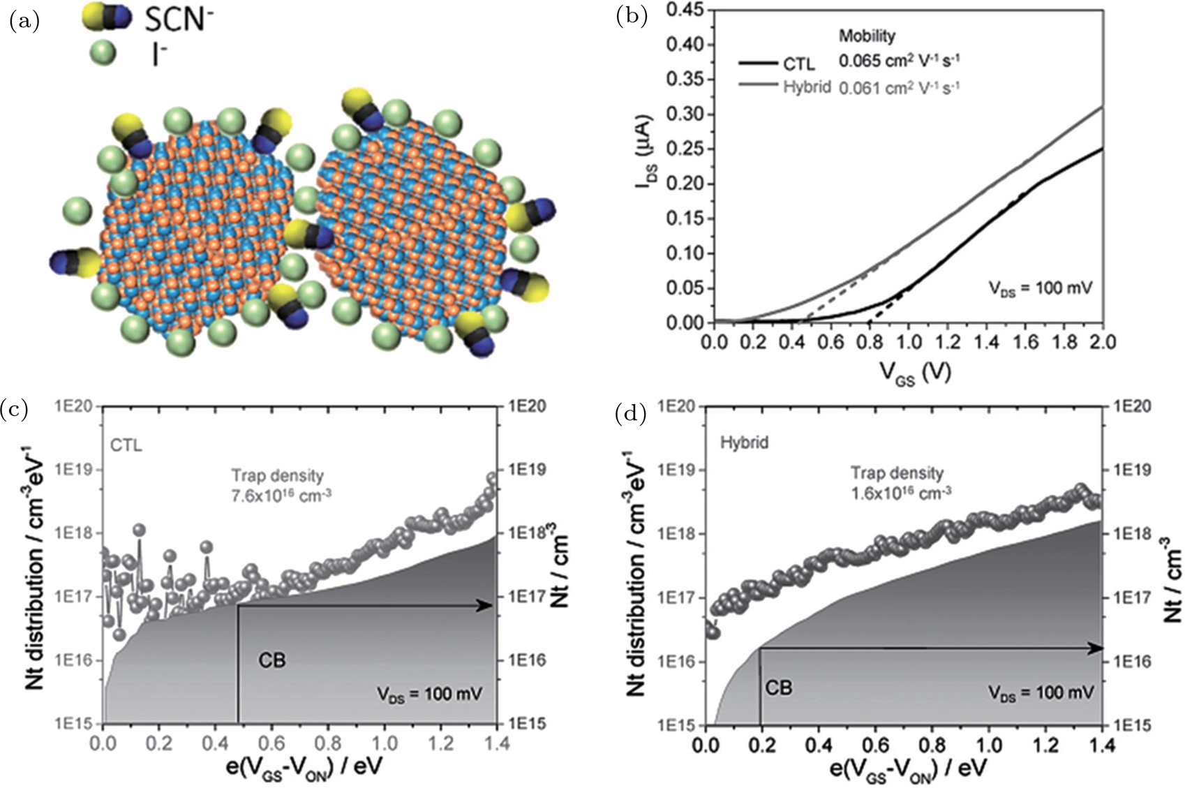
CQD films are generally fabricated by lay-by-layer spin coating, spray coating, inkjet printing, and dip coating, all of which involve repeated quantum dot deposition, solid-state ligand exchanges, and rinse steps, resulting in low quantum dot utilization and high solvent consumption. In contrast, fabricating CQD films based on pre-exchanged CQD inks, namely, the solution-based ligand-exchange method, the CQD film can be coated in a single deposition step, which was developed by Fischer.[135,136] Ning et al. reported the first photovoltaic device based on solution-phase inorganic-ligand-exchanged n-type CQD ink, wherein methylammonium iodide (MAI) was used as ligand.[124] Recently, organohalide perovskites (CH3NH3PbX3, X = I, Br, Cl) have been used to passivate CQDs by both solid-state ligand exchange and solution ligand exchange in view of their long hole and electron diffusion lengths, broad visible absorption range, and high charge mobility, more importantly, CH3NH3PbX3 shows perfect lattice matching with PbS CQDs. Most recently, methylammonium lead triiodide perovskite (MAPbI3)-ligand passivated PbS CQD films have been prepared, followed by annealing to form perovskite thin shells on the PbS CQD surfaces, then combined with PbS-EDT CQDs to fabricate hybrid quantum junction solar cells, presenting a high PCE of 8.95%.[137] A device with the structure of ITO/ZnO/[PbX3]/[PbX]+-PbS/EDT-PbS/Au (X = I, Cl, Br) was also fabricated, as shown in Fig. 13, wherein the [PbX3]/[PbX]+-passivated PbS CQD films were prepared by single-step spin-coating the [PbX3]/[PbX]+-capped CQD ink, while the PbS-EDT layers were fabricated via a layer-by-layer method. Unlike the MAI and MAPbI3 exchange, in which organic cations cannot be removed from the CQD surface unless annealing, clean [PbX3]/[PbX]+-capped CQDs was obtained, which can improve carrier transport, increase the active layer thickness up to 350 nm, and reduce the absorber bandgap to gain higher , thus leading to a certified PCE of 11.28% and good air-stability. Moreover, iodide passivated PbS CQDs were also obtained by doping in situ other than by ligand-exchange processes, in which iodide can substitute S and thus decrease the density of deep trap states of CQDs, Stavrinad et al. used 1-ethyl-3-methylimidazolium iodide (EMII) as iodide precursor to dope PbS CQDs, and the fabricated devices with structure of ITO/ZnO/PbS-I/PbS-EDT/Au have achieved a PCE of 10.47%.[138] Very recently, as shown in Fig. 14, a hybrid passivation approach by incorporation of I and SCN ions has been applied during the solution-exchange, which can remarkably reduce the trap density and enable the active layer thickness to reach the record-thickness of 500 nm, thus leading to the highest external quantum efficiency (EQE) of 80% at the excitonic peak and an impressive PCE of 11.2% with a high of 31.50 mA/cm2.[134]

Fig. 13. (color online) (a) Suggested formation dynamics of [PbX3]/[PbX]+ capped CQD solids. (b) HDR EQE measurement. (c) and (d) of three types of devices with different sizes of CQD. (e) Device performance with different active layer thicknesses.[131]
Fig. 14. (color online) (a) Schematic diagram of PbS CQD capped by I and SCN and separated by SCN. (b) Transfer characteristics of CTL (I capped CQDs) and hybrid CQD FETs. (c) and (d) Trap state densities (Nt) of CTL and hybrid CQD FETs.[134]
4. Conclusion and prospective

We review the recent advance in QDSCs and PbX CQD based solar cells, including high-quality CQD materials with good photoelectric properties and efficient strategies in suppressing carrier recombination, which made main contribution to the impressive enhancement of the device performance. For QDSCs, developing new QD sensitizer materials with relatively high conduction band and narrower bandgap is still crucial for enhancing . Besides, the current limitation for cell efficiency is mainly attributed to the low , further research is needed to exploit lower potential electrolyte species or hole-transport materials and design efficient counter electrode materials with better catalytic activity and conductivity, which enables reduced recombination loss and higher electron collection efficiency. For PbX CQD based solar cells, the quantum junction presents an attractive approach through careful engineering electrode materials and tuning the CQD properties, which is supposed to give better device performance. In addition, more passivation approaches are needed to further increase carrier diffusion length and thus allow for increasing thickness of CQDs active layer without compromising charge extraction.

Reference
[1] Burst J M Duenow J N Albin D S Colegrove E Reese M O Aguiar J A Jiang C S Patel M K Al-Jassim M M Kuciauskas D Swain S Ablekim T Lynn K G Metzger W K 2016 Nat. Energ. 1 16055
[2] Chirila A Reinhard P Pianezzi F Bloesch P Uhl A R Fella C Kranz L Keller D Gretener C Hagendorfer H Jaeger D Erni R Nishiwaki S Buecheler S Tiwari A N 2013 Nat. Mater. 12 1107
[3] Yoshikawa K Kawasaki H Yoshida W Irie T Konishi K Nakano K Uto T Adachi D Kanematsu M Uzu H Yamamoto K 2017 Nat. Energ. 2 17032
[4] Park N G Gratzel M Miyasaka T Emery K 2016 Nature Energ. 1 8
[5] Zuo C T Bolink H J Han H W Huang J S Cahen D Ding L M 2016 Adv. Sci. 3 1500324
[6] Gong J Sumathy K Qiao Q Zhou Z 2017 Renew. Sust. Energ. Rev. 68 13
[7] Hagfeldt A Boschloo G Sun L Kloo L Pettersson H 2010 Chem. Rev. 110 9
[8] Dai S X Zhao F W Zhang Q Q Lau T K Li T F Liu K Ling Q D Wang C R Lu X H You W Zhan X W 2017 J. Am. Chem. Soc. 139 1336
[9] Jiao S Du J Du Z L Long D H Jiang W Y Pan Z X Li Y Zhong X H 2017 J. Phys. Chem. Lett. 8 559
[10] Kagan C R Lifshitz E Sargent E H Talapin D V 2016 Science 353 aac5523
[11] hi J Huang Q Wan Q Xu X 2016 Acta Phys.-Chim. Sin. 32 822
[12] Huynh W U Dittmer J J Alivisatos A P 2002 Science 295 2425
[13] Lei Y Jia H He W Zhang Y Mi L Hou H Zhu G Zheng Z 2012 J. Am. Chem. Soc. 134 17392
[14] Beard M C Luther J M Semonin O E Nozik A J 2013 Accounts Chem. Res. 46 1252
[15] Semonin O E Luther J M Choi S Chen H Y Gao J B Nozik A J Beard M C 2011 Science 334 1530
[16] Shabaev A Hellberg C S Efros A L 2013 Accounts Chem. Res. 46 1242
[17] Zhang J B Gao J B Church C P Miller E M Luther J M Klimov V I Beard M C 2014 Nano Lett. 14 6010
[18] Ji M Park S Connor S T Mokari T Cui Y Gaffney K J 2009 Nano Lett. 9 1217
[19] Hanna M C Beard M C Nozik A J 2012 J. Phys. Chem. Lett. 3 2857
[20] https://www.nrel.gov/pv/assets/images/efficiency-chart.png.
[21] Yu J Wang W R Pan Z X Du J Ren Z W Xue W N Zhong X H 2017 J. Mater. Chem. 5 14124
[22] Emin S Singh S P Han L Y Satoh N Islam A 2011 Sol. Energy 85 1264
[23] Sogabe T Shen Q Yamaguchi K 2016 J. Photon. Energy 6 040901
[24] Li W Zhong X H 2015 J. Phys. Chem. Lett. 6 11
[25] Zhao K Pan Z X Zhong X H 2016 J. Phys. Chem. Lett. 7 406
[26] Kramer I J Sargent E H 2014 Chem. Rev. 114 863
[27] Lan X Masala S Sargent E H 2014 Nat. Mater. 13 8
[28] Wei H Y Wang G S Wu H J Luo Y H Li D M Meng Q B 2016 Acta Phys. Chim. Sin. 32 201
[29] Albero J Clifford J N Palomares E 2014 Coordin. Chem. Rev. 263–264 12
[30] Chuang C H Lee Y L 2007 Appl. Phys. Lett. 91 053503
[31] Lee H Wang M Chen P Gamelin D R Zakeeruddin S M Gratzel M Nazeeruddin M K 2009 Nano Lett. 9 7
[32] Zhang Q X Guo X Z Huang X M Huang S Q Li D M Luo Y H Shen Q Toyoda T Meng Q B 2012 Phys. Chem. Chem. Phys. 13 9
[33] Badawi A 2015 Chin. Phys. 24 047205
[34] Zhang Q X Chen G P Yang Y Y Shen X Zhang Y D Li C H Yu R C Luo Y H Li D M Meng Q B 2012 Phys. Chem. Chem. Phys. 14 6479
[35] Zhang Q X Guo X Z Huang X M Huang S Q Li D M Luo Y H Shen Q Toyoda T Meng Q B 2011 Phys. Chem. Chem. Phys. 13 4659
[36] Tian J J Lv L L Fei C B Wang Y Liu X G Cao G Z 2014 J. Mater. Chem. A 2 7
[37] Bai Y Han C Chen X Q Yu H Zong X Li Z Wang L Z 2015 Nano Energy 13 609
[38] Huang F Zhang L S Zhang Q F Hou J Wang H G Wang H L Peng S L Liu J S Cao G Z 2016 ACS Appl. Mater. Inter. 8 34482
[39] Jiao S Wang J Shen Q Li Y Zhong X H 2016 J. Mater. Chem. 4 7214
[40] Koleilat G I Levina L Shukla H Myrskog S H Hinds S Pattantyus-Abraham A G Sargent E H 2008 ACS Nano 2 833
[41] Scholes G D Rumbles G 2006 Nat. Mater. 5 920
[42] Schoolar R B Dixon J R 1965 Phys. Rev. 137 4
[43] Lee J W Son D Y Ahn T K Shin H W Kim I Y Hwang S J Ko M J Sul S Han H Park N G 2013 Sci. Rep. 3 1050
[44] Pan Z X Zhao K Wang J Zhang H Feng Y Y Zhong X H 2013 ACS Nano 7 5215
[45] Kim S Kang M Kim S Heo J H Noh J H Im S H Seok S I Kim S W 2013 ACS Nano 7 4756
[46] Pan Z X Mora-Sero I Shen Q Zhang H Li Y Zhao K Wang J Zhong X H Bisquert J 2014 J. Am. Chem. Soc. 136 9203
[47] Du J Du Z L Hu J S Pan Z X Shen Q Sung J K Long D H Dong H Sun L T Zhong X H Wan L J 2016 J. Am. Chem. Soc. 138 4201
[48] Bai B Kou D X Zhou W H Zhou Z J Wu S X 2015 Green Chem. 17 4377
[49] Li T L Lee Y L Teng H 2012 Energ. Environ. Sci. 5 5315
[50] McDaniel H Fuke N Makarov N S Pietryga J M Klimov V I 2013 Nature Commun. 4 2887
[51] McDaniel H Fuke N Pietryga J M Klimov V I 2013 J. Phys. Chem. Lett. 245 355
[52] Zarei H Malekfar R 2016 Chin. Phys. 25 027103
[53] Lopez N Reichertz L A Yu K M Campman K Walukiewicz W 2011 Phys. Rev. Lett. 106 028701
[54] Okada Y Ekins-Daukes N J Kita T Tamaki R Yoshida M Pusch A Hess O Phillips C C Farrell D J Yoshida K Ahsan N Shoji Y Sogabe T Guillemoles J F 2015 Appl. Phys. Rev. 2 021302
[55] Hu X Zhang Q X Huang X M Li D M Luo Y H Meng Q B 2011 J. Mater. Chem. 21 15903
[56] Luo J H Wei H Y Huang Q L Hu X Zhao H F Yu R C Li D M Luo Y H Meng Q B 2013 Chem. Commun. 49 3881
[57] Luo J H Wei H Y Li F Huang Q L Li D M Luo Y H Meng Q B 2014 Chem. Commun. 50 3464
[58] Wei H Y Wang G S Luo Y H Li D M Meng Q B 2015 Electrochim. Acta 173 156
[59] Wei H Y Wang G S Shi J J Wu H J Luo Y H Li D M Meng Q B 2016 J. Mater. Chem. 4 14194
[60] Jiao S Shen Q Mora-Sero I Wang J Pan Z X Zhao K Kuga Y Zhong X H Bisquert J 2015 ACS Nano 9 908
[61] Itzhakov S Shen H Buhbut S Lin H Oron D 2012 J. Phys. Chem. C 117 8
[62] Wang J Han H 2010 J. Colloid Interf. Sci. 351 5
[63] Wu K Liang G Kong D Chen J Chen Z Shan X McBride J R Lian T 2016 Chem. Sci. 7 7
[64] Wang J Mora-Sero I Pan Z X Zhao K Zhang H Feng Y Y Yang G Zhong X H Bisquert J 2013 J. Am. Chem. Soc. 135 15913
[65] Ahmed R Zhao L Mozer A J Will G Bell J Wang H X 2015 J. Phys. Chem. C 119 2297
[66] Brennan T P Trejo O Roelofs K E Xu J Prinz F B Bent S F 2013 J. Phys. Chem. A 1 7566
[67] Kim D H Losego M D Peng Q Parsons G N 2016 Adv. Mater. Interf. 3 1600354
[68] Shen T Tian J J Li B Cao G Z 2016 Sci. Chin. Mater. 59 833
[69] Ren Z W Wang J Pan Z X Zhao K Zhang H Li Y Zhao Y X Mora-Sero I Bisquert J Zhong X H 2015 Chem. Mater. 27 8398
[70] Zhao K Pan Z X Mora-Sero I Canovas E Wang H Song Y Gong X Q Wang J Bonn M Bisquert J Zhong X H 2015 J. Am. Chem. Soc. 137 5602
[71] Jiang G Pan Z Ren Z Du J Yang C Wang W Zhong X 2016 J. Phys. Chem. A 29 6
[72] Du J Meng X X Zhao K Li Y Zhong X H 2015 J. Phys. Chem. A 3 17091
[73] Xia R Wang S Dong W Fang X 2017 Acta Phys. -Chin. Sin. 33 670
[74] Deng M H Huang S Q Zhang Q X Li D M Luo Y H Shen Q Toyoda T Meng Q B 2010 Chem. Lett. 39 1168
[75] Yang Y Zhu L Sun H Huang X M Luo Y H Li D M Meng Q B 2012 ACS Appl. Mater. Inter. 4 7
[76] Zhang X L Huang X M Yang Y Y Wang S Gong Y Luo Y H Li D M Meng Q B 2013 ACS Appl. Mater. Inter. 5 5954
[77] Xu J Xiao J Don J Luo Y H Li D M Meng Q B 2014 Electrochim. Acta 127 6
[78] Kamaja C K Devarapalli R R Shelke M V 2017 ChemElectroChem 4 6
[79] Ghosh D Halder G Sahasrabudhe A Bhattacharyya S 2016 Nanoscale 8 10632
[80] Zhang H Yang C Du Z L Pan D Y Zhong X H 2017 J. Mater. Chem. 5 1614
[81] Pan Z X Zhang H Cheng K Hou Y M Hua J L Zhong X H 2012 ACS Nano 6 3982
[82] Yang J W Wang J Zhao K Izuishi T Li Y Shen Q Zhong X H 2015 J. Phys. Chem. 119 28800
[83] Wang G S Wei H Y Luo Y H Wu H J Li D M Zhong X H Meng Q B 2016 J. Power Sources 302 266
[84] Wang G S Wei H Y Shi J J Xu Y Z Wu H J Luo Y H Li D M Meng Q B 2017 Nano Energy 35 17
[85] Wang J Li Y Shen Q Izuishi T Pan Z X Zhao K Zhong X H 2016 J. Mater. Chem. 4 877
[86] Yang J W Zhong X H 2016 J. Mater. Chem. 4 16553
[87] Peng W X Du J Pan Z X Nakazawa N Sun J K Du. Z.L. 2017 ACS Appl. Mater. Inter. 9 5328
[88] BSambur J Novet T Parkinson B A 2010 Science 330 4
[89] Cheng Y Arinze E S Palmquist N Thon S M 2016 Nanophotonics 5 31
[90] Hines M A Scholes G D 2003 Adv. Mater 15 1844
[91] Ma W Swisher S L Ewers T Engel J Ferry V E Atwater H A Alivisatos P 2011 ACS Nano 5 8140
[92] Moreels I Justo Y De Geyter B Haustraete K Martins J C Hens Z 2011 ACS Nano 5 2004
[93] Piliego C Protesescu L Bisri S Z Kovalenko M V Loi M A 2013 Energ. Environ. Sci. 6 3054
[94] Jean J Chang S Brown P R Cheng J J Rekemeyer P H Bawendi M G Gradecak S Bulovic V 2013 Adv. Mater 25 2790
[95] Chuang C H M Brown P R Bulovic V Bawendi M G 2014 Nat. Mater. 13 796
[96] Clifford J P Konstantatos G Johnston K W Hoogland S Levina L Sargent E H 2009 Nat. Nanotech. 4 5
[97] Luther J M Gao J B Lloyd M T Semonin O E Beard M C Nozik A J 2010 Adv. Mater 22 3704
[98] Choi H Kim J K Song J H Kim Y 2013 Appl. Phys. Lett. 102 193902
[99] Luther J M Law M Song Q Perkins C L Beard M C Nozik A J 2008 ACS Nano 2 271
[100] Ma W Luther J M Zheng H M Wu Y Alivisatos A P 2009 Nano Lett. 9 1699
[101] Szendrei K Gomulya W Yarema M Heiss W Loi M A 2010 Appl. Phys. Lett. 97 203501
[102] Tang J Wang X H Brzozowski L Barkhouse D A R Debnath R Levina L Sargent E H 2010 Adv. Mater 22 1398
[103] Choi M J Oh J Yoo J K Choi J Sim D M Jung Y S 2014 Energ. Environ. Sci. 7 3052
[104] Mai X D An H J Song J H Jang J Kim S Jeong S 2014 J. Materials Chem. A 2 7
[105] Jeong K S Tang J Liu H Kim J Schaefer A W Kemp K Levina L Wang X H Hoogland S Debnath R Brzozowski L Sargent E H Asbury J B 2012 ACS Nano 6 89
[106] Pal B N Robel I Mohite A Laocharoensuk R Werder D J Klimov V I 2012 Adv. Funct. Mater. 22 1741
[107] Tang J A Sargent E H 2011 Adv. Mater. 23 12
[108] Johnston K W Pattantyus-Abraham A G Clifford J P Myrskog S H Hoogland S Shukla H Klem E J D Levina L Sargent E H 2008 Appl. Phys. Lett. 92 122111
[109] Luther J M Law M Beard M C Reese M O Ellingson R J Nozik A J 2008 Nano Lett. 8 5
[110] Pattantyus-Abraham A G Kramer I J Barkhouse A R Wang X H Konstantatos G Debnath R Levina L Raabe I Nazeeruddin M K Gratzel M Sargent E H 2010 ACS Nano 4 3374
[111] Yuan M J Voznyy O Zhitomirsky D Kanjanaboos P Sargent E H 2015 Adv. Mater. 27 917
[112] Kemp K W Labelle A J Thon S M Ip A H Kramer I J Hoogl S Sargent E H 2013 Adv. Energ. Mater. 9 6
[113] Tan F Wang Z Qu S Cao D Liu K Jiang Q Yang Y Pang S Zhang W Lei Y Wang Z 2016 Nanoscale 8 7
[114] Zhao T S Goodwin E D Guo J Wang H Diroll B T Murray C B Kagan C R 2016 ACS Nano 10 9267
[115] Wu R F Yang Y H Li M Z Qin D H Zhang Y D Hou L T 2017 Nanomater 7 201
[116] Tang J Liu H Zhitomirsky D Hoogland S Wang X H Furukawa M Levina L Sargent E H 2012 Nano Lett. 12 6
[117] Liu H Tang J Kramer I J Debnath R Koleilat G I Wang X H Fisher A Li R Brzozowski L Levina L Sargent E H 2011 Adv. Mater. 23 3832
[118] Liu H Zhitomirsky D Hoogland S Tang J Kramer I J Ning Z J Sargent E H 2012 Appl. Phys. Lett. 101 151112
[119] Peng H W Song J H Kanatzidis M G Freeman A J 2011 Phys. Rev. 84 125207
[120] Speirs M J Dirin D N Abdu-Aguye M Balazs D M Kovalenko M V Loi M A 2016 Energ. Environ. Sci. 9 2916
[121] Speirs M J Balazs D M Dirin D N Kovalenko M V Loi M A 2017 Appl. Phys. Lett. 110 103904
[122] Kim G-H Arquer F P G Yoon Y J Lan X Liu M Voznyy O Yang Z Fan F Ip A H Kanjanaboos P Hoogland S Kim J Y Sargent E H 2015 Nano Lett. 15 6
[123] Ning Z J Voznyy O Pan J Hoogland S Adinolfi V Xu J X Li M Kirmani A R Sun J P Minor J Kemp K W Dong H P Rollny L Labelle A Carey G Sutherland B Hill I G Amassian A Liu H Tang J Bakr O M Sargent E H 2014 Nat. Mater. 13 822
[124] Ning Z J Zhitomirsky D Adinolfi V Sutherland B Xu J X Voznyy O Maraghechi P Lan X Z Hoogland S Ren Y Sargent E H 2013 Adv. Mater. 25 1719
[125] Jin Z W Yuan M J Li H Yang H Zhou Q Liu H B Lan X Z Liu M X Wang J Z Sargent E H Li Y L 2016 Adv. Funct. Mater. 26 5284
[126] Remacle F 2000 J. Phys. Chem. 104 4739
[127] Ip A H Thon S M Hoogland S Voznyy O Zhitomirsky D Debnath R Levina L Rollny L R Carey G H Fischer A Kemp K W Kramer I J Ning Z J Labelle A J Chou K W Amassian A Sargent E H 2012 Nat. Nanotech. 7 577
[128] Ning Z J Ren Y Hoogland S Voznyy O Levina L Stadler P Lan X Z Zhitomirsky D Sargent E H 2012 Adv. Mater. 24 6295
[129] Tang J Kemp K W Hoogland S Jeong K S Liu H Levina L Furukawa M Wang X H Debnath R Cha D K Chou K W Fischer A Amassian A Asbury J B Sargent E H 2011 Nat. Mater. 10 765
[130] Milliron D J 2014 Nat. Mater. 13 772
[131] Liu M X Voznyy O Sabatini R de Arquer F P G Munir R Balawi A H Lan X Z Fan F J Walters G Kirmani A R Hoogland S Laquai F Amassian A Sargent E H 2017 Nat. Mater. 16 258
[132] Lan X Z Voznyy O Kiani A de Arquer F P G Abbas A S Kim G H Liu M X Yang Z Y Walters G Xu J X Yuan M J Ning Z J Fan F J Kanjanaboos P Kramer I Zhitomirsky D Lee P Perelgut A Hoogland S Sargent E H 2016 Adv. Mater. 28 299
[133] Lan X Z Voznyy O de Arquer F P G Liu M X Xu J X Proppe A H Walters G Fan F J Tan H R Liu M Yang Z Y Hoogland S Sargent E H 2016 Nano Lett. 16 4630
[134] Sun B Voznyy O Tan H R Stadler P Liu M X Walters G Proppe A H Liu M Fan J Zhuang T T Li J Wei M Y Xu J X Kim Y Hoogland S Sargent E H 2017 Adv. Mater. 29 1700749
[135] Fischer A Rollny L Pan J Carey G H Thon S M Hoogland S Voznyy O Zhitomirsky D Kim J Y Bakr O M Sargent E H 2013 Adv. Mater. 25 5742
[136] Kiani A Sutherland B R Kim Y Ouellette O Levina L Walters G Dinh C T Liu M X Voznyy O Lan X Z Labelle A J Ip A H Proppe A Ahmed G H Mohammed O F Hoogland S Sargent E H 2016 Appl. Phys. Lett. 109 183105
[137] Yang Z Y Janmohamed A Lan X Z de Arquer F P G Voznyy O Yassitepe E Kim G H Ning Z J Gong X W Comin R Sargent E H 2015 Nano Lett. 15 7539
[138] Stavrinadis A Pradhan S Papagiorgis P Itskos G Konstantatos G 2017 ACS Energ. Lett. 2 739
[139] Peng J J Chen Y N Zhang X F Dong A G Liang Z Q 2016 Adv. Sci. 3 1500432
[140] Kim B S Neo D C J Hou B Park J B Cho Y Zhang N L Hong J Pak S Lee S Sohn J I Assender H E Watt A A R Cha S Kim J M 2016 ACS Appl. Mater. Inter. 8 13902
[141] Liu M X de Arquer F P G Li Y Y Lan X Z Kim G H Voznyy O Jagadamma L K Abbas A S Hoogland S Lu Z H Kim J Y Amassian A Sargent E H 2016 Adv. Mater. 28 4142
[142] Zhang J B Gao J B Miller E M Luther J M Beard M C 2014 ACS Nano 8 614
[143] Baek S W Song J H Choi W Song H Jeong S Lee J Y 2015 Adv. Mater. 27 8102