A combined system for generating a uniform magnetic field and its application in the investigation of Efimov physics
Yao Rui1, 2, Sun Zhen-Dong1, 2, Zhou Shu-Yu1, †, Wang Ying3, ‡, Wang Yu-Zhu1
Key Laboratory for Quantum Optics, Shanghai Institute of Optics andFine Mechanics, Chinese Academy of Sciences, Shanghai 201800, China
Department of Physics, University of Science and Technology of China, Hefei 230026, China
School of Science, Jiangsu University of Science and Technology, Zhenjiang 212003, China


† Corresponding author. E-mail: syz@siom.ac.cn wangying@just.edu.cn

Abstract

We propose a scheme to produce a uniform magnetic field with a system comprising a pair of coils and an atom chip. After optimizing the parameters of the chip wires, we improve the homogeneity of the magnetic field by two orders of magnitude. We exhibit that this method can be applied in the investigation of Efimov physics in 87Rb–40K mixture.

1. Introduction

As a powerful tool to control interactions between atoms, magnetic Feshbach resonances have been widely applied to explore a vast array of phenomena in ultracold atomic and molecular quantum gases.[1,2] This has led to a number of intriguing physical phenomena such as the observation of a “Bosenova” from a controlled collapse in a Bose–Einstein condensate (BEC),[3] the sonic analog of a gravitational black hole in a BEC,[4,5] the creation of ultracold molecules,[6] and the investigation of Efimov physics in three-body systems.[79] In many experiments, a large scattering length is necessary, so the magnetic field must be tuned very close to the resonance point. Even slight fluctuations or inhomogeneity of the magnetic field will change the scattering length dramatically and lead to failure. The stability can be enhanced significantly by applying a feedback control to the current in the coils and shielding the external magnetic fields. However, the homogeneity of the magnetic field depends on the configuration of the coils. The nonuniformity of the magnetic field also hinders the atoms from reaching ultralow temperatures, which could cause serious problems in some experiments.

Several kinds of coils have been applied to generate uniform magnetic fields, of which the most commonly used is a Helmholtz coil.[10] A Helmholtz coil consists of two identical coaxial circular coils separated by a distance h which equals to the radius R of the coil, and each one carries an equal electric current in the same direction. Another important coil, the saddle-shaped coil,[11] can produce a magnetic field with higher uniformity than a Helmholtz coil of the same scale. However, both cannot be used in some experiments owing to their geometry or dissipation power. For example, there are tens of windows in the vacuum chamber of the multipurpose cold atomic experimental device, in which we utilize the design. The coils should not block any light path around the chamber. For some experiments involving Feshbach resonance between 87Rb–40K mixture, a uniform magnetic field as high as 550 G with power dissipation less than 1000 W is required. In the evaporative cooling phase, the coils are also utilized to generate a quadrupole magnetic field for trapping atoms.[12] Therefore, neither a Helmholtz coil nor a saddle-shaped coil satisfies all these demands. In our preliminary design, we set a pair of coils at the exterior regions of the top and bottom windows of the chamber, which can produce 550 G with power dissipation of approximately 800 W, but it does not meet the requirement for the uniformity of the magnetic field.

In this paper, we propose an alternative way to improve the homogeneity, which combines magnetic fields created by currents in both macroscopic coils and wires on a chip. Our calculation shows that the magnetic field produced by the chip wires cancels most of the inhomogeneity of the magnetic field created by the macroscopic coils. As an example of an application, we demonstrate that this system can be used to explore the Efimov effect in 87Rb–40K mixture with a scattering length up to , which has not been achieved before.

2. Scheme for the generation of a magnetic field
2.1. Generating a magnetic field by the current in a pair of coils

The magnetic field generated by the current in a single coil is[13]
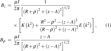
Here, R is the radius of the coil, and A is the position of the coil in the z axis. The argument of the complete elliptic integrals K and E is In the Cartesian coordinate system,

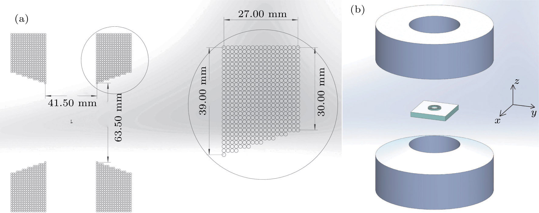
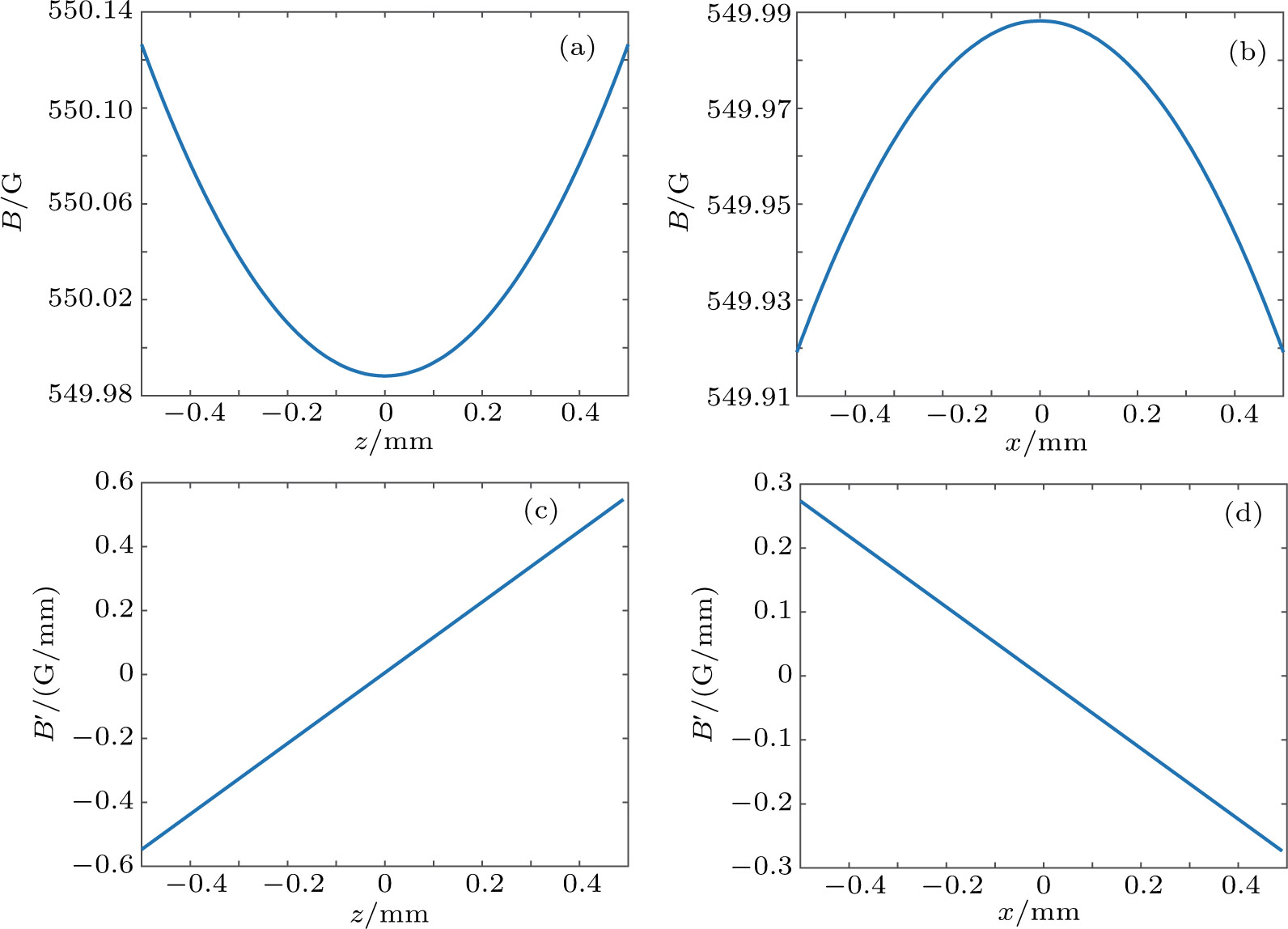
The configuration of the coil assembly is shown in Fig. 1(a). We apply Eqs. (1)–(5) to calculate the magnetic field generated by each coil and then accumulate all of them. The clockwise current in the coil assembly is set to 20.411 A, which produces a magnetic field of 550 G in the central region. Figure 2(a) presents the variation of B along the x and z axes. The variation is approximately 140 mG in the cubic space of 1 mm3 at the central area and 5.6 mG in region around the center. The distribution of the field strength along each axis is quadratic and the center is a saddle point. The quadratic feature of the magnetic field is confirmed because the magnetic field gradients along the z and x axes are well behaved and linear, as shown in Figs. 2(c) and 2(d).

Fig. 1. (color online) (a) Structure and winding details of coils. (b) A sketch of the coils atom chip combined system.
Fig. 2. (color online) The magnetic field generated by a pair of coils. (a) The magnetic field strength along the z axis. (b) The magnetic field strength along the x axis. (c) The magnetic field gradient along the z axis. (d) The magnetic field gradient along the x axis.
2.2. Improving the homogeneity of the magnetic field by adding an atom chip

The foregoing calculation indicates that the magnetic field along the z axis can be expressed as where is the magnetic field at the center, and the factor C is obtained by fitting the curve. In principle, we can cancel the nonuniformity of the magnetic field by adding a magnetic field with the opposite linear gradient. We implement the scheme with current-carrying wires on an atom chip.[14,15] Considering the current limit of the chip wires and the symmetry, we use several concentric circular wires on the chip. The coordinate of the chip surface in the z axis is z1. At point z, the distance from the chip surface is .

The magnetic field around the height h0 in the symmetry axis, which is produced by the current in a single circular coil on the chip, can be expanded as

where h0 is the height from the chip surface to the center of the atomic cloud. Because we are only concern about the magnetic field in a small region, the fourth- and higher-order terms can be ignored. Therefore, the magnetic field produced by a single circular current is where all coefficients are given by the derivatives of each order. We now put n concentric circular currents on the chip, the total magnetic field along the symmetry axis is We then rewrite the expression of the magnetic field produced by the macroscopic pairs at the coordinate h as The combined magnetic field is To improve the uniformity, all terms of h, h2, and h3 should be eliminated. This leads to the following adjustments.

1) A3 equates to zero. This can be achieved by adjusting the radius of the ring after is set. For a single circular current, the third-order derivative is where R is the radius of the ring. When , the third-order derivative is zero.

For several rings, we set their radius around and make the third-order derivatives cancel each other.

2) To eliminate the terms of h2, the coefficients should satisfy . This can be realized by adjusting the current in the chip coils.

3) To eliminate the terms of h, we adjust the position of the chip surface z1. It is easy to find that the condition is

4) To generate the required magnetic field, we change the current in the pairs and chip wires with the same factor.

Owing to the zero-divergence of the magnetic fields and the axial symmetry of the system, once we reduce the space variation of the magnetic field along the z axis, the space variation of the magnetic field along the x and y axes is also canceled within a limited region.

We then perform a numerical simulation with the above steps. First, we set and apply five circle currents. The central radii of the rings are , , R, R+d, and R+2d, respectively. The width of all circle wires is 0.2 mm, and the gap between adjacent wires is 0.01 mm, so d = 0.21 mm. The thickness of all these wires is . When we estimate the parameters with the aforementioned processes, we ignore the width of the wires. However, when we calculate the magnetic field, we consider the effect of the finite wires widths by assuming uniform current density.

We now estimate the parameters following steps 1 to 3 when the current in the coils is 20.082 A. We obtain R=3.4641 mm and . The current on the chip wires is , which can be calculated from A2. We then obtain and .

The first step of the parameter estimation process is based on a single ring with a thin wire that is slightly different from the real case. By slightly modifying z1 to −5.5809 mm, we can further improve the homogeneity of the magnetic field. With the above parameters, the magnetic field strength at the central area is approximately 538.203 G. To compare with the case of the coil assembly, we adjust the value to 550 G by multiplying a factor of approximately 1.022 to all currents.

Figure 3 shows the final calculation result. The homogeneity of the magnetic field has been improved remarkably, especially in the small region near the minims. The magnetic field varies by only 0.04 mG in the region of around the minims field point . Compared with 5.6 mG in the case of the coil pair only, the homogeneity of the magnetic field has been improved by approximately two orders of magnitude.

Fig. 3. (color online) The magnetic field generated by a coils_atom chip combined system. (a) The pseudo-color image of the magnetic field strength in the plane. (b) Field strength along the axis. (c) Field strength along the (0,0,z) axis.
2.3. Other technical points of the atom chip

To avoid the extra magnetic field generated by currents in wires that connect the rings on the chip and the current feed through, each pair of wires carrying the input and output currents is set closely parallel on the other side of the chip. They connect the corresponding rings by using through-wafer interconnect technology.[16] The distance between each pair of parallel wires is only tens of microns, so the magnetic fields in our area of concern cancel each other. The chip can be glued on a copper support, which is fixed to the vacuum chamber. To avoid the possible conduction between the chip wires on the rear side with the metal mount, an insulating layer of silicon dioxide is coated on the rear side of the chip. The typical resistance of all the chip wires is approximately 10 Ω, so the system adds only approximately 30 W of power. The power is still in the permissible range.

Because the atomic cloud is 3 mm from the chip surface, there is enough space to put another layer of chip covering on it. The added top layer can be fabricated by other wires for different experimental purposes. It is also beneficial that the top layer is a mirror with high optical quality, which is a benefit to some experiments involving a reflection image or optical lattices.[17,18]

3. Application of this scheme in the investigation of Efimov physics
3.1. Efimov physics in heteronuclear mixture of 40K–87Rb

We now turn our attention to Efimov physics, which is a universal phenomenon in quantum three-body systems. Efimov predicted a universal set of bound trimer states appearing for three identical bosons with a resonant two-body interaction.[7] These states even exist in the absence of a corresponding two-body bound state. Efimov-related loss resonances as a function of a have been observed in ultracold homonuclear and heteronuclear atomic systems.[8,9] However, these resonances in the rates of inelastic collisions between three atoms of 87Rb–40K mixture have not been observed.[19,20] Further work is needed to resolve this contradiction. In 87Rb–40K mixture, the dominant three-body recombination process is 87Rb+87Rb +40K, and the 87Rb+40K+40K loss is suppressed by Fermi statistics. 87Rb and 40K atoms are prepared in the and states, respectively, which are the lowest energy hyperfine states in a magnetic field. The atom loss rate is given by where and are the densities of 87Rb and 40K, respectively, and α is the loss rate coefficient. We apply the magnetic Feshbach resonance to control the interactions between 87Rb and 40K atoms. In a magnetically tunable Feshbach resonance, the s-wave scattering length a is a function of the magnetic field B where is the background scattering length, and B0 denotes the resonance position. For 87Rb–40K mixture which we discuss in this paper, the parameters are (a0 is the Bohr radius), , and .

At negative a, whereas for positive a, where the coefficients , , , and is the mass of 40K.

3.2. Application of the combined magnetic field scheme in the research of Efimov physics
3.2.1. Resonance peaks broadened in inhomogeneous magnetic fields

In real experiments, owing to the inhomogeneity of the magnetic fields, the loss rate coefficient α has spatial variation. Thus, the atom loss rate should be rewritten as We will then calculate the initial atom loss rate versus the magnetic field in the center of the atomic cloud based on Eq. (18).

The Efimov effect is a few-body physical effect, so the temperature of 87Rb atoms should be higher than the Bose–Einstein condensation transition temperature to avoid many-body effects. Therefore, can be approximated as a Gaussian distribution where , and ωx is the trap frequency along the x direction, and σy and σz are defined in the same way. is the mass of the 87Rb atom. The atom number is . The temperature of 40K is slightly lower than Fermi temperature . However, it is still valid to approximate its density distribution as a Gaussian distribution when we perform a semiquantitative analysis.

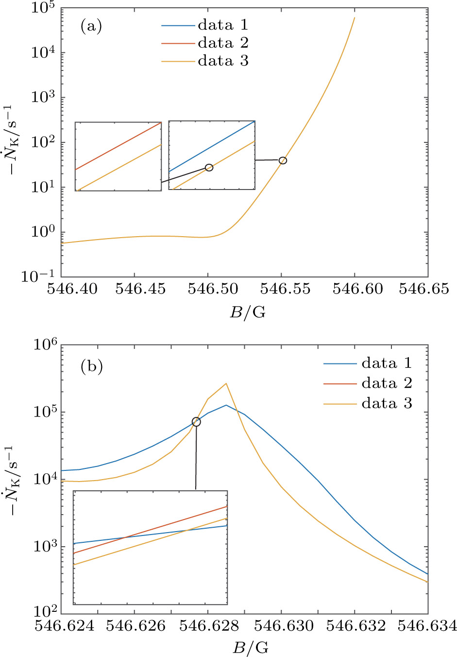
Our calculation is based on two sets of parameters. The parameters of the first group are , T = 3 nK, , , , ; the parameters of the second group are , T = 600 pK, , , , . Figure 4 shows the calculation results. For the parameters in the first group, the atom loss rates are almost the same regardless of whether the magnetic field is generated by coils only or a combined system or in the uniform case. Meanwhile, for the parameters in the second group, the peak atomic loss rate is broadened when we use the magnetic field generated by the coils only, but the peak is almost not broadened with the magnetic field produced by the combined system.

Fig. 4. (color online) The atom loss rate versus the magnetic field strength in the central region. Data 1, data 2, and data 3 show the magnetic fields generated by coils only, a combined system, and a uniform magnetic field, respectively. (a) The results with the parameters of the first group. (b) The results with the parameters of the second group.
3.2.2. Temperature limit in inhomogeneous stray magnetic fields

Another undesirable effect of inhomogeneous stray magnetic fields is that they limit the lowest atom temperature. This effect is more critical than the broadened resonance peaks. The atoms are trapped in an optical trap so the optical potential is at the same order of temperature as the atomic cloud. If the potential induced by inhomogeneous stray magnetic fields is comparable with the optical potential, the atomic cloud will escape from the trap. In the experiment we discussed above, the observation range of is limited to , where is the thermal wave number, is the Boltzmann constant, and μ is the reduced mass for 40K and 87Rb.[21] Previous experiments measured the loss rate coefficient α versus a within , which was limited by the temperature T = 300 nK. If we want to check Efimov resonances with higher , a lower temperature of the atomic sample is necessary. For example, to check the resonance peak at approximately , the temperature should be lowered to 600 pK, along with the parameters of the second group. The ultralow temperature can be reached by adiabatic decompression of the trap after evaporative cooling and sympathetic cooling. In the process of an adiabatic decompression, the temperature of atoms is proportional to the average trap frequency. With a reasonable estimation, we assume that the initial temperature of 87Rb atoms is 600 nK with the trap frequency of . Therefore, when we adiabatically reduce the trap frequency to or , the corresponding temperature of 87Rb atoms can be lowered to 3 nK or 600 pK. When the trap frequency and temperature , the size of the 87Rb atomic cloud in the trap is . The magnetic field variation in the concerned region of from the center is approximately 1.4 mG or 0.01 mG for the magnetic field produced by the macroscopic coil pairs only or the combined magnetic field. For the latter case, the potential variation for the state of 87Rb is equivalent to approximately 0.35 nK, which is much smaller than the trap potential. For the macroscopic coil pairs only, the spatial potential variation of the same state is up to 49 nK. Therefore, the nonuniformity of the combined magnetic field only slightly changes the density distribution of the atomic cloud. However, in the case of the macroscopic coil pairs, the potential variation is larger than the trap potential, so we must add some kind of potential compensation, which can be implemented by spatially modulated far detuned laser beams.

We then check another group of experimental parameters. When the trap frequency and temperature , the scale of the atomic cloud in the trap is . We are concerned with the variation of magnetic fields in the region of from the center. In the case of macroscopic pairs only, the variation of the magnetic field in this region is approximately 5.6 mG and the potential variation for the state of 87Rb is near 200 nK. Meanwhile, in the case of the combined magnetic field, the potential variation is approximately 1.4 nK. Both are higher than the trap potential, but for the combined magnetic field, it is easy to be compensated because the potential variation is only several times of the trap potential strength. For the coil assembly only, the compensation optical field becomes very difficult to realize because it should match the spatial potential variation of the magnetic field with the precision of 10−3.

3.2.3. Other benefits of the combined system

Our method also has the benefits of fast and precise control of the magnetic fields. It is difficult to implement precise and fast control of the current in regular coils owing to their considerable inductance. The inductance of the chip wires is lower by several orders, so the response time can be reduced remarkably. This is crucial for the kind of experiment where the magnetic field is set to the value near the resonance position. For instance, in the preceding section, we discussed the experiment with the scattering length : the fluctuation of the magnetic field on the order of 10 mG is sufficiently large to wipe off the resonance peak. We reduce the fluctuation of the magnetic field by applying both a slow feedback to the macroscopic coils and a fast feedback to the chip wires. The response time of the currents in the chip wires is on the order of microseconds, which is fast enough for manipulation of the magnetic field in most experiments.

4. Conclusion and perspectives

In conclusion, we have proposed a scheme to obtain a uniform magnetic field by combining the magnetic fields generated by currents in macroscopic coils and chip wires. The homogeneity of the magnetic field has been improved by two orders of magnitude compared with the method that uses only the coil assembly. This method can be applied in the experiment for investigating the Efimov effect in 87Rb–40K mixture. The test range of the scattering length is extended to more than 55000a0, which is sufficient to compare with the theoretical prediction. Recent experimental and theoretical work already revealed the Efimov resonance departure from the universal prediction.[22] Our scheme provides an experimental approach for further investigation.

Reference
[1] Chin C Grimm R Julienne P Tiesinga E 2010 Rev. Mod. Phys. 82 1225
[2] Wang P J Fu Z K Chai S J Zhang J 2011 Chin. Phys. 20 103401
[3] Donley E A Claussen N R Cornish S L Roberts J L Cornell E A Wieman C E 2001 Nature 412 295
[4] Kurita Y Morinari T 2007 Phys. Rev. 76 053603
[5] Wang Y Zhou Y Zhou S Y 2016 Sci. Rep. 6 38512
[6] Regal C A Ticknor C Bohn J L Jin D S 2003 Nature 424 47
[7] Efimov V 1970 Phys. Lett. 33 563
[8] Kraemer T Mark M Waldburger P Danzl J G Chin C Engeser B Lange A D Pilch K Jaakkola A Näger H C Grimm R 2006 Nature 440 315
[9] Barontini G Weber C Rabatti F Catani J Thalhammer G Inguscio M Minardi F 2009 Phys. Rev. Lett. 103 043201
[10] Crosser M S Scott S Clark A Wilt P M 2010 Rev. Sci. Instr. 81 084701
[11] Ginsberg D M Melchner M J 1970 Rev. Sci. Instr. 41 122
[12] Zhou S Y Qian J Zhang S C Wang Y Z 2016 Chin. Opt. Lett. 14 070202
[13] Bergeman T Erez G Metcalf H J 1987 Phys. Rev. 35 1535
[14] Folman R Krueger P Schmiedmayer J Denschlag J Henkel C 2002 Adv. At. Mol. Opt. 48 263
[15] Yan B Cheng F Ke M Li X L Tang J Y Wang Y Z 2009 Chin. Phys. 18 4259
[16] Salim E A DeNatale J Farkas D M Hudek K M McBride S E Michalchuk J Mihailovich R Anderson D Z 2011 Quantum Inf. Process 10 975
[17] Xu Q F Liu H Lu B Q Wang Y B Yin M J Kong D H Ren J Tian X Chang H 2015 Chin. Opt. Lett. 13 100201
[18] Zhu S B Qian J Wang Y Z 2017 Chin. Opt. Lett. 15 060202
[19] Bloom R S Hu M G Cumby T D Jin D S 2013 Phys. Rev. Lett. 111 106301
[20] Hu M G Bloom R S Jin D S Goldwin J M 2014 Phys. Rev. 90 013619
[21] D’Incao J P Suno H Esry B D 2004 Phys. Rev. Lett. 93 123201
[22] Johansen J DeSalvo B J Patel K Chin C 2017 Nat. Phys. 13 731