Surface plasmon resonance-induced tunable polarization filters based on nanoscale gold film-coated photonic crystal fibers
Liu Yingchao, Chen Hailiang, Li Shuguang, Liu Qiang, Li Jianshe
Hebei Key Laboratory of Microstructure Materials Physics, College of Science, Yanshan University, Qinhuangdao 066004, China


† Corresponding author. E-mail: hlchen@ysu.edu.cn

Project supported by the National Natural Science Foundation of China (Grant Nos. 61505175 and 61475134) and the Natural Science Foundation of Hebei Province, China (Grant Nos. F2017203110 and F2017203193).

Abstract

Surface plasmon resonance induced tunable polarization filters based on nanoscale gold film-coated photonic crystal fibers were proposed and analyzed. The characteristics of the polarization filter were calculated by finite element method (FEM). The gold film was selectively coated on the inner wall of one cladding air hole which was located near the fiber core along the y-axis direction. When the phase of core fundamental mode and surface plasmon polaritons (SPPs) mode matches,the two modes couple with each other intensely. Numerical results show that the resonance wavelength and strength vary with fiber structural parameters and the index of the infilling liquid. The fiber parameters were optimized to achieve specific functions. Under the optimal structure, we realized a dual channel filter at the communication wavelength of 1.31 µm and 1.55 µm for y polarization direction and x polarization direction. Then a single channel polarized filter at the communication wavelength of 1.55 µm is also achieved by adjusting the refractive index of the infilling liquid. The proposed polarization filters realized dual channel filtering and single channel filtering simultaneously under the same structure for the first time to the best of our knowledge.

1. Introduction

Photonic crystal fiber (PCF),[1,2] also known as the microstructure fiber, wraps light within microstructure of air holes that are arranged in a certain order in the transmission. In recent years, it has attracted widespread attention owing to some novel properties. The characteristics of high birefringence are good for the design of polarization components and can be generated by arranging the air holes asymmetrically. With the development of simulation and fabrication technology, the PCF of different structures being selectively infiltrated with functional materials provides a promising platform for novel photonic functional devices with the advantages of tunability, flexibility in design, all-in-fiber structure and integration, such as optical switches, filters, polarization splitter, modulators, dispersion compensators, and optical fiber sensors.[35]

Surface plasmon polaritons (SPPs)[6,7] are infrared or visible-frequency electromagnetic waves that propagate along a metal–dielectric interface. When the SPPs are stimulated by the incident light, the energy of the incident light can transfer to the surface of the gold film in the case of phase matching. This phenomenon is called surface plasmon resonance (SPR).[8] The transmission spectrum of the incident light appears as a dip when SPR happens.

Optical fiber polarizing devices[911] are essential components for optical sensors and communication systems. The traditional polarizers including sheet polarizer, prism polarizer, and brewster-angle polarizer have shortcomings such as high cost, high loss, mechanical instability and difficulties integrating with the optical communication networks or optical sensors,[12] while the surface plasmon resonance induced polarization filters can overcome the above disadvantages. In metal film coated PCFs, the light transmitted in the fiber-core can couple to SPPs as phase matching happens. So at the phase matching points, the fundamental modes appear as loss peaks which makes the PCFs have the potential to be in-fiber polarization filters. Zhang et al.[13] have shown selective coating in air holes of PCF via precipitation from a reduction reaction. Liu et al.[14] reported a tunable fiber polarization filter by filling different index liquids and gold wire into photonic crystal fiber. As for the selective filling, there are many techniques to achieve such as collapsing air-holes, injection-cleave techniques[15,16] and direct manual gluing.[1720] Xue et al.[21] proposed an infiltrate PCF polarization filter based on SPR. The results exhibit that the resonance loss can reach 508 dB/cm for y polarization mode at the wavelength of 1311 nm and the full width half maximum (FWHM) is 20 nm. Hameed et al.[22] designed a tunable gold wire filled PCF polarization filter. The design has a central hole filled with a nematic liquid crystal to produce good adjustability with external electric field or temperature. Liu et al.[23] reported a nanoscale gold film coated PCF polarization filter for the range of 1.31, 1.48, and 1.55 μm. The shortcoming of it is that the authors have to change the size of the air hole coated with gold film to gain the polarization filtering at the three wavelengths.

In this paper, we designed a tunable liquid-filled PCF polarization filter based on SPR with nanoscale gold film. It can realize dual channel polarization filtering at the communication wavelength of 1.31 μm and 1.55 μm in y and x polarization directions. We can also obtain a single channel filtering at the wavelength of 1.55 μm in the y polarization direction by adjusting the index of liquid without changing the structural parameters. The values of extinction ratio at the above wavelengths are 104, −92, and 171 dB respectively, which are better than those obtained in Ref. [23].

2. Geometry and simulation method

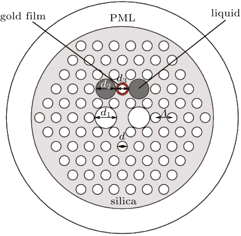
The structure of the designed PCF polarization filter is shown in Fig. 1. The air holes are arranged in the hexagonal structure. Two large air holes of diameter d1 are introduced in the solid core region of the PCF to achieve high birefringence. The diameter of the air hole coated with gold film is d3. The two big gray air holes on both sides of it are filled with liquid of diameter d2. The diameter of other holes is set as d. The thickness of the gold film is t and the lattice pitch of the air holes is Λ.

Fig. 1. (color online) Cross section of the proposed PCF polarization filter. The background material is pure silica glass. The air hole with the diameter of d3 is coated with gold film and the two air holes with the diameter of d2 are filled with liquid. The diameter of the microstructure area of the designed fiber is 22 μm.

The mode birefringence of the PCFs can be expressed as

where and are the real part of the effective refractive indices in y and x polarization modes, respectively. We can form the asymmetric structure by increasing d1 and d2 to achieve high birefringence of the PCF. Based on prior analysis, the polarization splitting SPR in the gold film-coated HB-PCFs is caused by the high birefringence. In this way, the resonance wavelengths of X-polarized mode and Y-polarized mode could be separated obviously.

The background material is pure silica and the dispersion relation is calculated using the Sellmeier equation[24]

where A = 0.691663, B = 0.407943, C = 0.897479, D = 0.004679, E = 0.013512, F = 97.934003. We have used the Drude–Lorentz model for calculation of the permittivity of the gold film:[25]
The characteristics of the filter have been calculated through Comsol Multiphysics software packages based on the finite element method. The calculation area is divided into 19238 triangular subdomains under d1 = 2.6 μm, d2 = 2.4 μm, d3 = 1.2 μm, d = 1.2 μm, t = 30 nm, and Λ = 2 μm.

3. Result and discussion
3.1. Dispersion relations

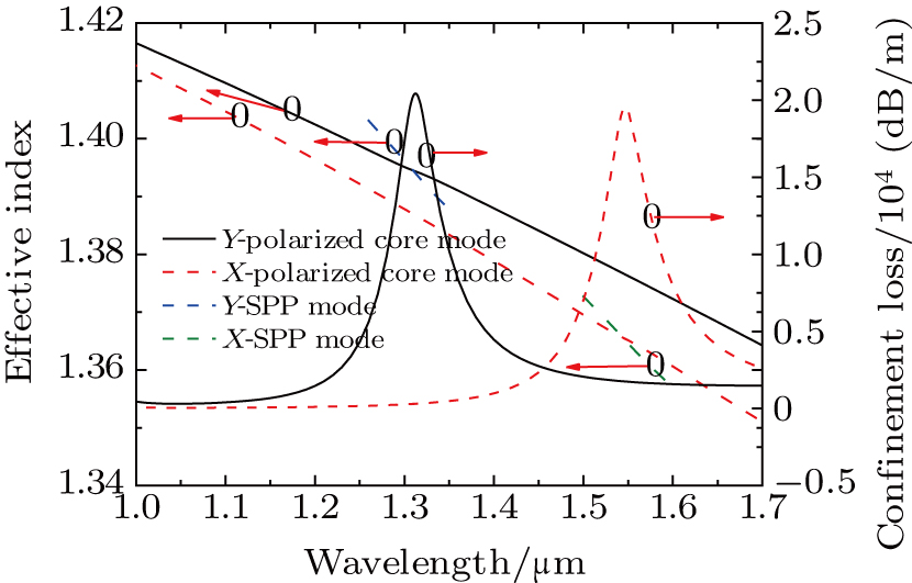
The electric field distributions of core fundamental modes in (a) the Y polarization direction, (b) the X polarization direction, and 2-nd SPP modes in (c) the Y polarization direction, and (d) the X polarization direction are shown in Fig. 2, respectively. When the phase of core fundamental mode and SPP mode matches, the core fundamental mode in the Y polarization direction couples to the 2-nd SPP mode in the Y polarization direction and the core fundamental mode in the X polarization direction couples to the 2-nd SPP mode in the X polarization direction as shown in Fig. 3 and Fig. 4, correspondingly. The couplings between core fundamental modes and higher order SPP modes are discussed in Ref. [23]. The modal loss can be defined as

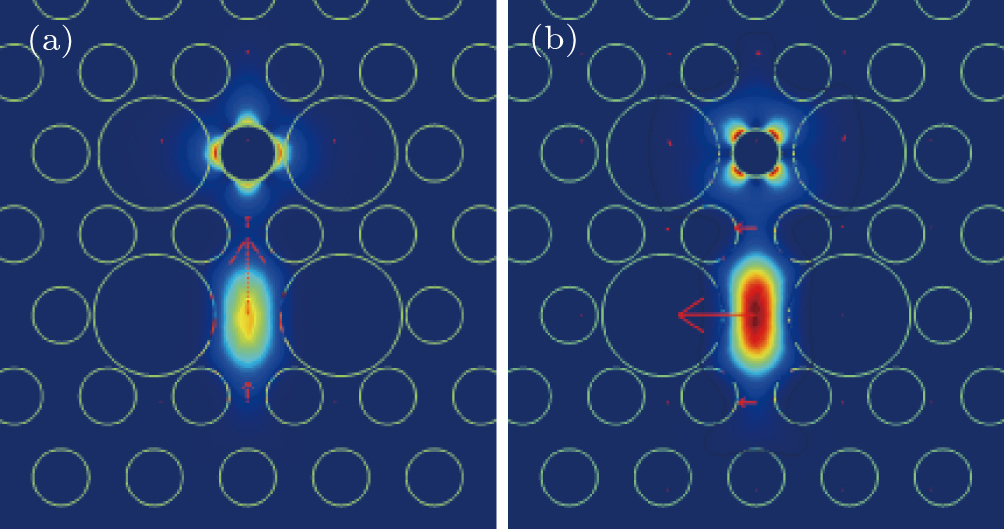
where λ is the wave-length of the incident light, Im[neff] represents the imaginary part of the effective refractive index, the unit of loss is dB/m. The dispersion relation of core guided modes and SPP modes and loss spectra of core guided modes are shown in Fig. 3. The structure parameters are taken as: d1 = 2.6 μm, d2 = 2.4 μm, d3 = 1.2 μm, d = 1.2 μm, t = 30 nm, and Λ = 2 μm. When the phase matching condition is satisfied, the core mode couples to the corresponding SPP mode, and as a result the loss spectrum appears as a peak or peaks, which could be used for a polarization filter. The coupling style is divided into complete coupling and incomplete coupling, which is described in Ref. [21] in detail. The resonance wavelength in the Y-polarized direction is 1.31 μm and that in the X-polarized direction is 1.55 μm. The corresponding mode field distribution of the Y-polarized mode and the X-polarized mode are shown in Fig. 4. It can be seen that a part of the energy of core modes transfers to the surface of the gold film.

Fig. 2. (color online) Electric field distributions of core fundamental modes in (a) Y-polarized direction, (b) X-polarized direction, and 2-nd SPP modes in (c) Y-polarized direction, (d) X-polarized direction. The Y-polarized core mode couples to Y-SPP mode and X-polarized core mode couples to X-SPP mode when their phase matching condition is satisfied.
Fig. 3. (color online) Dispersion relation of core guided modes and SPP modes and confinement loss spectra of core modes. The structural parameters are d1 = 2.6 μm, d2 = 2.4 μm, d3 = 1.2 μm, d = 1.2 μm, t = 30 nm, and Λ = 2 μm. The resonance wavelength in the Y-polarized direction is 1.31 μm and that in the X-polarized direction is 1.55 μm. The confinement loss of the Y-polarized and X-polarized core modes are 20305 dB/m and 19358 dB/m respectively.
Fig. 4. (color online) The electric field distribution of (a) Y-polarization mode at the wavelength of 1.31 μm and (b) X-polarization mode at the wavelength of 1.55 μm. A part of the energy of core modes transfers to the surface of the gold film.
3.2. The simulation results

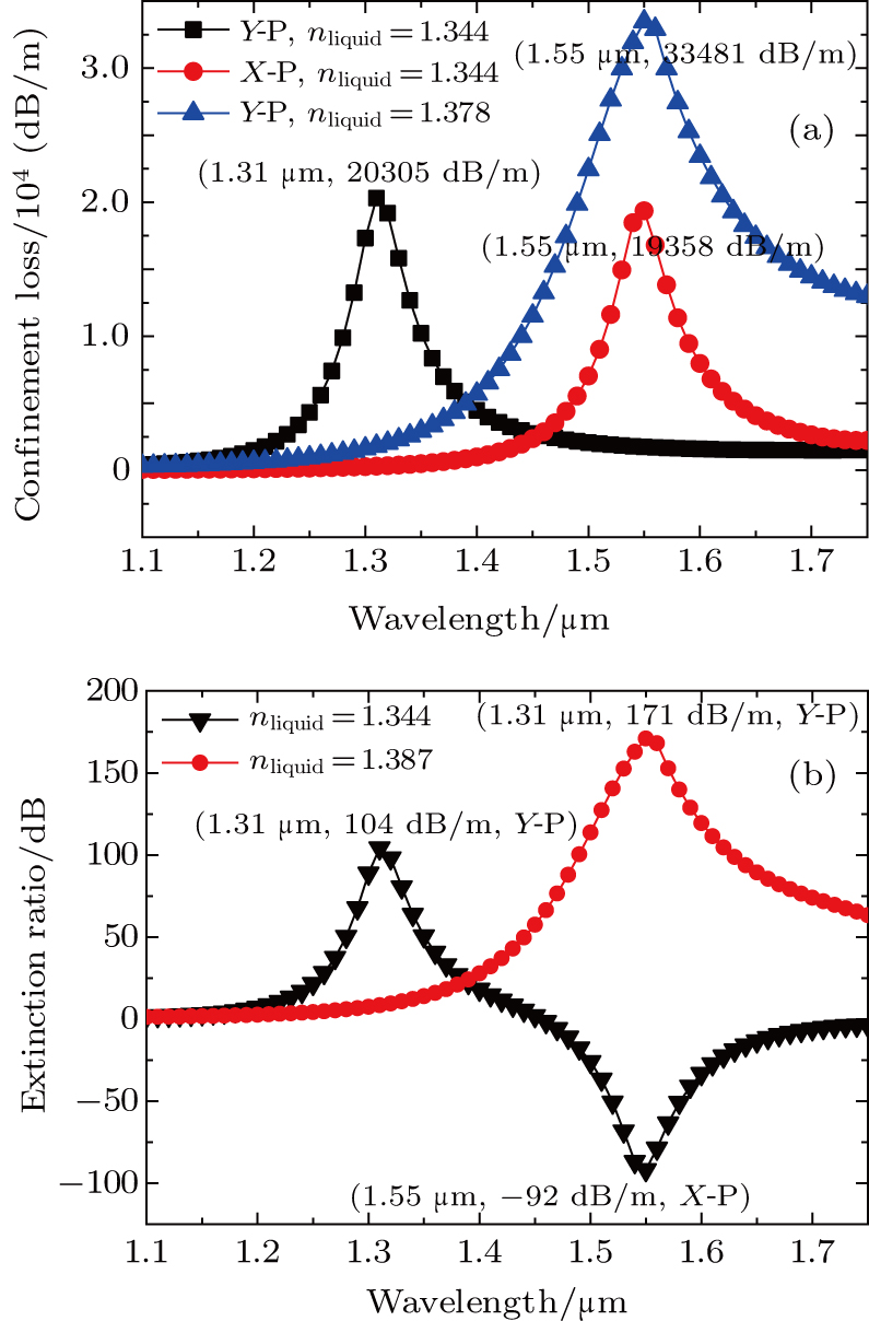
In Fig. 5, when the liquid index is 1.344, under the optimal structure parameters that d1 = 2.6 μm, d2 = 2.4 μm, d3 = 1.2 μm, d = 1.2 μm, t = 30 nm, and Λ = 2 μm, we get a dual channel polarization filter at the communication wavelength of 1.31 μm and 1.55 μm for y polarization and x polarization. The corresponding extinction ratios are 104 dB and −92 dB, respectively. When we adjust the liquid index to 1.387, we get a single channel filter at the communication wavelength of 1.55 μm for y polarization, and its ER is 171 dB. ER is one of the most important parameters to measure the performance of a polarization filter. When the ER is better than 20 dB or −20 dB, the two polarized modes could be separated obviously. The variation of ER with fiber length is described in Ref. [21] in detail. The ER increases as fiber length increases. The length of our proposed filter is only 0.6 mm, so the tiny fiber filter can be easily integrated into a compact instrument, which is useful in the miniaturization of an integrated system.

Fig. 5. (color online) (a) Confinement loss dependence on the wavelength when the liquid index is 1.344, 1.387, respectively, (b) when liquid index is 1.344 and 1.387 the corresponding ER dependence on the operable wavelength λ. The structural parameters are d1 = 2.6 μm, d2 = 2.4 μm, d3 = 1.2 μm, d = 1.2 μm, t = 30 nm, and Λ = 2 μm. We realize the tunable polarization filter simply by adjusting the liquid index.
3.3. The optimization process of the structure

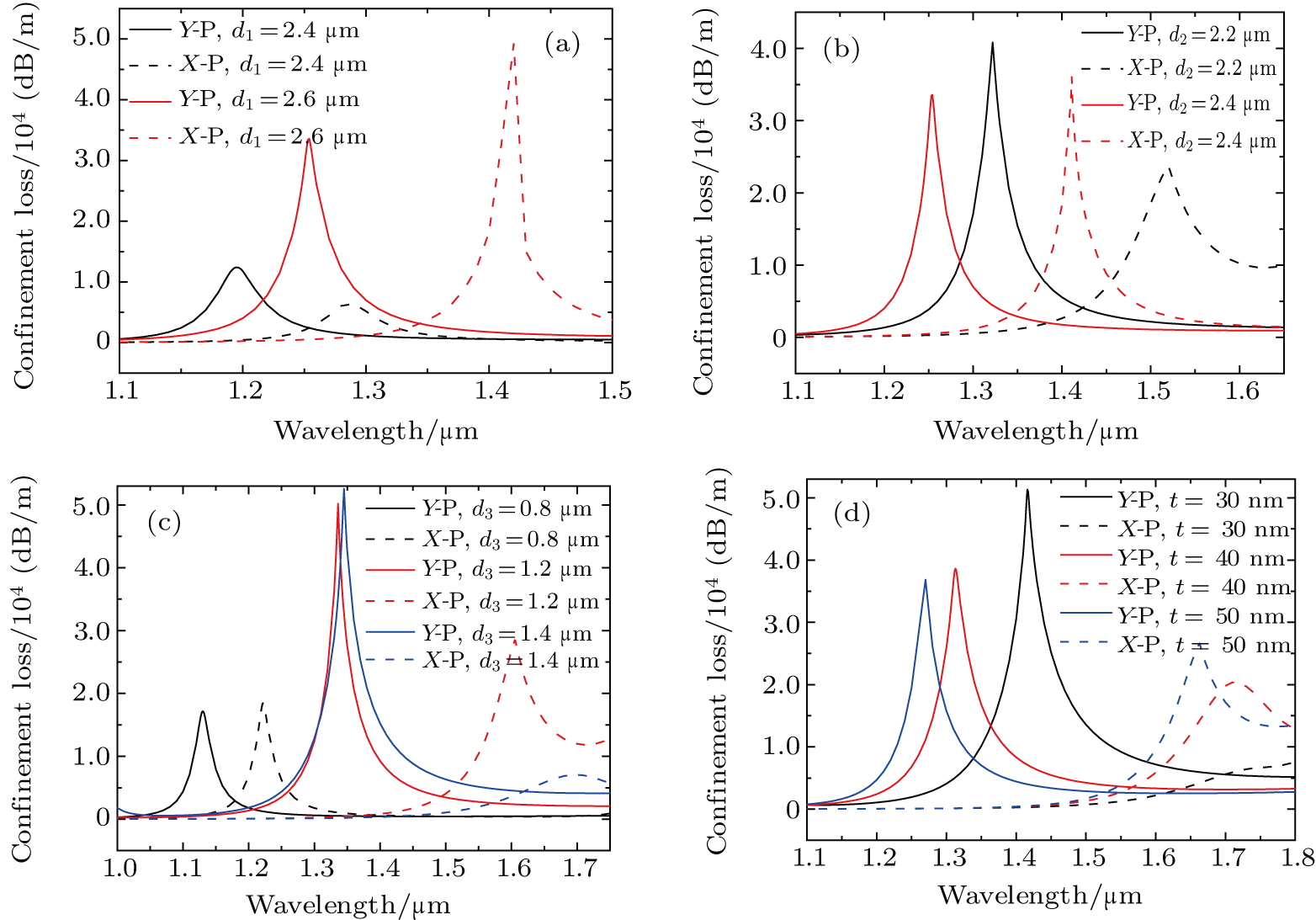
The effects of geometrical parameters of d1, d2, d3, and t on the filtering characteristics of the polarization filter are discussed below to acquire the optimal structure. The other structural parameters are set as d = 1.2 μm, Λ = 2 μm. The resonance loss dependence on the wavelength of λ in X-polarization direction and Y-polarization direction is shown in Fig. 6. In Fig. 6(a), d1 is set as 2.4, 2.6 μm, respectively, while the other parameters are set as d2 = 2.4 μm, d3 = 1 μm, t = 40 nm, nliquid = 1.37. It can be seen from Fig. 6(a) that the resonance wavelengths of Y-polarized (Y-P) and X-polarized (X-P) mode experience a red shift when d1 increases. Because the refractive index of core mode decreases and that of the SPP mode does not change obviously, the phase matching point experiences a red shift which can be inferred from Fig. 3. The resonance loss of Y-polarized and X-polarized modes increase obviously with the increase of d1, especially for the X-polarized mode. So we can increase d1 to gain stronger resonance strength and longer resonance wavelength of Y-polarized and X-polarized modes, in the same way. In addition, when d1 = 2.4 μm the spacing between the resonance wavelength of Y-polarized and X-polarized modes is 0.09 μm and the spacing becomes 0.17 μm as d1 = 2.6 μm, which means the birefringence of the filter becomes higher with d1 increasing. Because high birefringence is helpful to separate the resonance wavelength positions of the two orthogonal polarized modes, so we can increase d1 to acquire higher birefringence. In Fig. 6(b), d2 is set as 2.2, 2.4 μm, respectively, and the other parameters are set as d1 = 2.6 μm, d3 = 1 μm, nliquid = 1.37. It is found that the resonance wavelengths of Y-polarized and X-polarized modes experience a blue shift with d2 increasing. Because the refractive index of SPP mode decreases and that of the core mode does not change obviously which results in the blue shift of the resonance wavelengths. So we can adjust d2 to obtain the appropriate resonance wavelength of Y-polarized and X-polarized modes. In Fig. 6(c), d3 is set as 0.8, 1.2, and 1.4 μm, respectively, while the other parameters are set as d1 = 2.6 μm, d2 = 2.4 μm, nliquid = 1.37. The resonance wavelengths of X-polarized mode and Y-polarized mode experience a red shift. When d3 = 1.2 μm the above structure is appropriate to be a Y-polarization filter. Because the resonance wavelength and intensity of Y-polarized mode is 1.34 μm and 52580 dB/m and the FWHM is 30 nm, which are all conductive to the good performance of a Y-polarization filter. So we can set d3 as 1.2 μm, when we want to design a Y-polarization filter. In Fig. 6(d), t is set as 30, 40, 50 nm, respectively, while the other parameters are set as d1 = 2.6 μm, d2 = 2.4 μm, d3 = 1.2 μm, nliquid = 1.366. The resonance wavelengths of Y-polarized and X-polarized modes blue shift as t increases. When t = 30 nm the intensity of resonance in the Y-polarization direction is the strongest. As a result, under the above structural parameters the thickness of gold film can be set as 30nm to be a Y-polarized filter. According to the above numerous simulations and analysis, the optimal structure parameters are set as d1 = 2.6 μm, d2 = 2.4 μm, d3 = 1.2 μm, t = 30 nm, d = 1.2 μm, and Λ = 2 μm. On the basis of this structure, we can adjust the refractive index of liquid to acquire a certain filter of good performance.

Fig. 6. (color online) The Confinement loss of the core mode dependence on the operable wavelength λ at different structural parameters (a) d1 = 2.4, 2.6 μm, (b) d2 = 2.2, 2.4 μm, (c) d3 = 0.8, 1.2, 1.4 μm, (d) t = 30, 40, 50 nm. The other structural parameters are d = 1.2 μm, Λ = 2 μm. The analysis helps us to alter the structural parameters or liquid index to realize the polarization filter at certain wavelength.
4. Conclusion

The tunable liquid-filled PCF polarization filters based on SPR were designed. The gold film was coated on the wall of the cladding air hole near the fiber core along the y-axis direction. The two air holes on both sides of it are filled with liquid. We can change the index of the liquid to adjust the phase matching point. The FV-FEM with PMLs was introduced. The effects of structural parameters on the polarization characteristics of the polarization filter were analyzed. When the structural parameters were d1 = 2.6 μm, d2 = 2.4 μm, d3 = 1.2 μm, t = 30 nm, d = 1.2 μm and liquid index nliquid = 1.344, we obtained a dual channel filter at the communication wavelength of 1.31 and 1.55 μm for y polarization and x polarization. When the liquid index was 1.387, it filtered out the communication wavelength 1.55 μm in the y polarized direction. The structure can be further optimized for better performance, and all the analyses were beneficial to further studies on other fiber-based plasmon devices. Moreover, the fiber length is only 0.6 mm and it can be easily integrated into a compact instrument, which is useful for the miniaturization of an optical integrated communication system.

Reference
[1] Russell P S J 2006 J. Lightw. Technol. 24 4729
[2] Knight J C Birks T A Russell P S J Atkin D M 1996 Opt. Lett. 21 1547
[3] Yao J Wang R Miao Y Lu Y Zhao X Jing L 2013 Chin. J. Lasers 1 003
[4] Liu Q Li S Wang X Shi M 2016 Chin. Phys. B 25 124210
[5] Wang X Li S Chen H Wang G Liu Q Zhao Y 2016 Plasmonics 11 1265
[6] Barnes W L Dereux A Ebbesen T W 2003 Nature 424 6950
[7] Johnstone W Stewart G Hart T 1990 J. Lightwave Technol. 8 538
[8] Homola J Yee S S Gauglitz G 1999 Sensor Actuat. B-Chem. 54 3
[9] Dyott R B Bello J Handerek V A 1987 Opt. Lett. 12 3
[10] Wei L Alkeskjold T T Bjarklev A 2009 IEEE Photon. Technol. Lett. 21 1633
[11] Qian W Zhao C L Wang Y Chan C C Liu S Jin W 2011 Opt. Lett. 16 3296
[12] Bao Q Zhang H Wang B Ni Z Lim C H Y X Wang Y Loh K P 2011 Nat. Photon. 5 411
[13] Zhang X Wang R Cox F M Kuhlmey B T Large M C J 2007 Opt. Express 15 16270
[14] Liu Q Li S Li J Dou C Wang X Wang G Shi M 2016 J. Lightwave Technol. 34 2484
[15] Nielsen K Noordegraaf D Sorensen T Bjarklev A Hansen T 2005 J. Opt. 7 8
[16] Huang Y Xu Y Yariv A 2004 Appl. Phys. Lett. 85 5182
[17] Schmidt M A Sempere L N P Tyagi K H Poulton G C Russell P S J 2008 Phys. Rev. 77 033417
[18] Kerbage C Steinvurzel P Reyes P Westbrook P Windeler R Hale A Eggleton B 2002 Opt. Lett. 27 842
[19] Zhang X Wang R Cox F M Kuhlmey B T Large M C 2007 Opt. Express 15 16270
[20] Wu D K Kuhlmey B T Eggleton B J 2008 Opt. Lett. 34 322
[21] Xue J R Li S G Xiao Y Qin W Xin X Zhu X 2013 Opt. Express 21 13733
[22] Hameed M F O Heikal A M Younis B M Abdelrazzak M Obayya S S A 2015 Opt. Express 23 7007
[23] Liu Q Li S G Chen H L 2015 IEEE Photon J. 7 2700210
[24] Agrawal G P 2000 Nonlinear Science at the Dawn of the 21st Century Berlin Springer-Verlag 195
[25] Vial A Grimault A S Macías D Barchiesi D 2005 Phys. Rev. B 71 085416
[26] Liu Q Li S G Li H Zi J C Zhang W Fan Z An G W Bao Y J 2015 Plasmonics 10 931