1. IntroductionTHz pulse based on its high-field transport and ultrafast characteristics has been applied to semiconductor modulation technology which has seen rapid development in recent years.[1–12] Especially, it is possible to study the nonlinear modulation of the carriers by THz pulse precision delay in semiconductors. For example, scholars have observed nonlinear ultrafast modulations of intense terahertz pulses in Ge, Si, GaAs, and InGaAs.[5,6] Su et al. studied the ultrafast dynamics of GaAs photoexcited carriers in THz field.[7] The nonlinear phenomenon about impact ionization and intervalley scattering are observed in InSb and InAs with intense terahertz pulses.[8–10]
As a way of reflecting the interaction between THz pulse and electrons, photoluminescence (PL) has attracted wide attention.[13–19] For instance, the THz-induced photoluminescence quenching phenomenon is observed by using the terahertz wave as a quenching source and the femtosecond laser with a wavelength of 800 nm as an excitation source.[14,19] Liu et al. in 2010 observed the PLQ phenomenon of CdTe and GaAs from single-cycle THz pulse by using the time-integrated PL spectra measurement.[15] In 2011, Bhattacharyya et al. reported that the free electron laser is used to study the time-resolved PLQ effect of semiconductor quantum wells,[16] and the magnetoexcitonic photoluminescences from GaAs/AlGaAs quantum wells were realized by time-resolved terahertz quenching in 2014.[17]
From the previous studies, we learn THz coherent detection based on time-resolved PL[19] in bulk semiconductor, and the PL intensity  shows some nonlinear characteristics with the change of THz field
  . However, from the view of THz field-modulation PL and measurement, it is hoped that
  changes with
  linearly, whose range needs expanding as much as possible. To solve the problems, further research has been performed. We select bulk material GaAs with lower n-doping density (
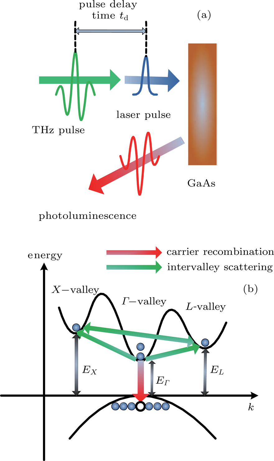
 ) for numerically analyzing the influence of THz wave on semiconductor carriers by using the ensemble Monte Carlo method.[19–23] Furthermore, in this work, the relationship between time-resolved PL intensity and THz pulse is studied (see Fig. 1). With the understanding of nonlinear characteristics, we study how to control PL sampling time and direct current (DC) field to realize the linear change, whose range can be determined and expanded. This study can provide the theoretical basis of THz field linear modulation in a larger range for new light emitting devices.
2. Physical modelIn the process of optical excitation-THz modulation, Boltzmann equations are used to describe the carrier–phonon system as follows:[19–22]
fk and
Nq are the distribution functions of electrons and phonons, respectively;

is the optical excitation probability;

and

are the probabilities of carrier–phonon and carrier–impurity scattering, respectively;

and

carrier–phonon and phonon–phonon interaction rates, respectively;

describes the process of THz-field-drive carriers,
e is the elementary charge,

the Planck constant, and
Et the THz field transmitted through the semiconductor.
[7] We use the ensemble Monte Carlo method to simulate the dynamics of carriers in the study.
[23] A three-alley model (

–
L–
X) is used to describe the nonparabolic conduction band structure. The carrier–phonon scattering rate mainly includes acoustic phonon scattering, intervalley scattering, intravalley scattering, polar optical phonon scattering, etc.
The parameters[19,24,25] used for calculation are as follows: laser wavelength λ = 800 nm; laser photon energy E = 1.54 eV; laser pulse width  ; bulk GaAs size: 1 mm × 1 mm; GaAs band gap
  ; intervalley energy
  ,
,  ; effective mass
  ,
,  ,
,  ,
,  ; lattice temperature:
  ; phonon energy (eV):
  ,
,  ,
,  ,
,  ,
,  ,
,  ; sound velocity
  ; lattice density ρ = 5.36 g/cm3; lattice constant
  Å; static dielectric function
  ; and high-frequency dielectric function
  .
.
3. Results and discussionThe laser pulse with a wavelength of 800 nm can effectively excite electrons from the valence band to the bottom of the conduction band. As the photon energy and GaAs band gap are close, the excited free carrier energy is very low. In the absence of THz pulse, the matching conditions of the wave vector are satisfied with the recombination of the electrons at the bottom of the conduction band  valley and the holes in the valence band. It has fast recombination luminescence without the participation of the phonons, thus forming PL. Under the intense THz field, free carriers will be accelerated thus transferred to a high-energy satellite valley outside the
  valley (the intervalley scattering). Those electrons cannot be directly recombined with holes in the valence band, resulting in weakening PL and forming PLQ (See Fig. 1).
In the time domain, the time-resolved PL intensity  is proportional to the electron density of the
  valley,[26,27] the variation of electron distribution in each valley can be obtained through solving the distribution Eqs. (1) and (2) by the EMC method. The electron density change in the
  valley can be defined as
where

and

are the electron density of the

valley in the presence and absence of a THz field, respectively. So the PL intensity

, the decrease proportion of electron concentration in the

valley is

, and then, the PLQ intensity

.
Therefore, we can investigate the changes of time-resolved PL by studying the P value. The linear and nonlinear variation characteristics of PL can be studied through the changes of P value with pulse delay time  , sampling time t, THz field
  , and DC field
  . Here,
  is the relative delay time between THz pluse and pump laser pulse, and
  means that the THz pulse precedes the peak of the laser pulse; t is the PL sampling time. The dynamic evolutions of carriers can be described by changing
  and t.
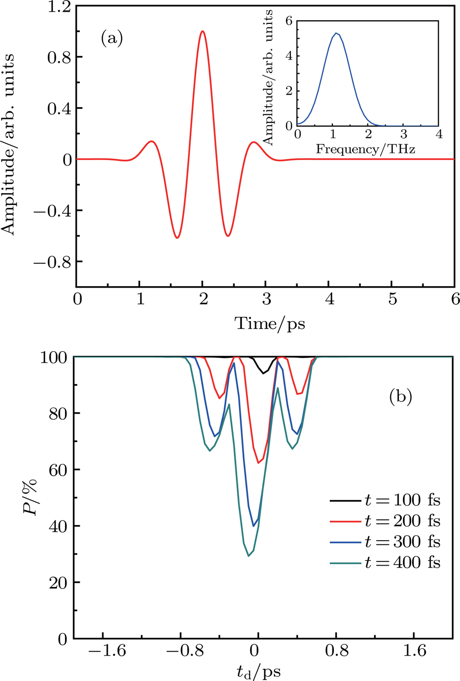
3.1. PL modulation by THz pulse without DC fieldFirst of all, we analyze the results of PL by directly modulating the THz field without a DC field. Figure 2(a) shows the incident THz field, with a center frequency of 1.1 THz. Figure 2(b) shows that the THz peak intensity is fixed to 100 kV/cm without the DC field. It can be found at different sampling time t, P value of electron density in  valley changes with pulse delay time
  . When the THz pulse peak coincides with the laser pulse peak (
 ), P is minimum, namely Q reaches a maximum value.
We can observe two phenomena. Firstly, the reduction of electron density corresponds to the intervalley scattering and PLQ. The P value is sensitive to the THz field intensity: the stronger strength of the THz field means that the P value is weakened more greatly, namely the intervalley scattering and PLQ rate are greater. Thus, the information about THz intensity can be well understood through the P value. However, there is no response for THz transient polarization direction, and the P value can only provide amplitude information no matter whether the drive pulse is positive or negative.
Secondly, the P value is different at different sampling time t. When t = 100 fs, P is relatively large, indicating that at the beginning of time, there are a small number of electrons involved in intervalley scattering. When t = 200 fs, the minimum of P is about 62%, with good linear effect. At 400 fs, the P value can reach 30%, but with the strengthened nonlinear characteristics. There is a certain distortion of P-value shape, as it is unable to respond well to THz intensity changes. In general, when t is relatively small, the PL shows a linear change with the THz intensity; when t is relatively large, the PL shows a nonlinear change.
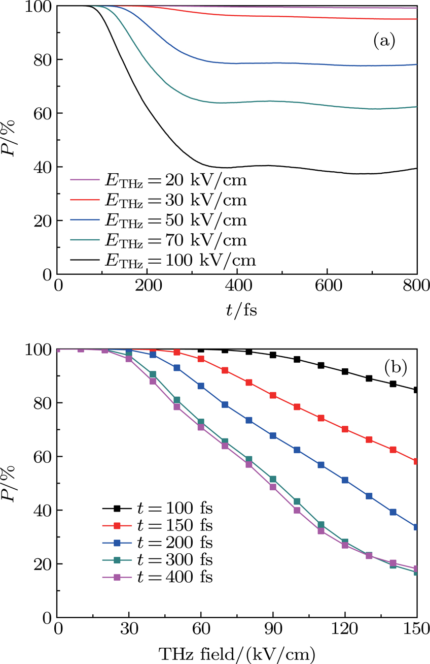
In order to understand the variation regulation of the P value at different values of sampling time t,  is fixed to be 0. Figure 3(a) shows that the peaks of Q (the lowest point of P) change with t under the different THz fields. At the beginning, the energy of electrons is not sufficient to cause the intervally scattering. With the unchanged number of electrons in the
  valley, the P value is 100%. After the time threshold, the P value decreases almost linearly, tending to be saturated after reaching the lowest point. The smaller THz field intensity results in the longer time to reach the threshold as well as the smaller linear range. When
  , it has a better linear relationship between 100 fs and 300 fs. If more than 300 fs, the electronic energy is gradually accumulated over time, in addition to the
  –L valley scattering, the
  –X valley scattering and the L–X scattering also occur. It leads to nonuniform energy absorption, gradually-saturated scattering and a little-changed P value. Comparing with Fig. 2(b) shows that the shape of P changes largely when
  , no longer with a significant linear relationship with THz waveform.
Figure 3(b) shows that the Q peak changes with THz field without DC field. We select and study the THz fields at 0 kV/cm–150 kV/cm (peak value). Firstly, THz intensity should exceed a certain threshold to effectively accelerate electrons, thus forming intervally scattering and photoluminescence quenching. Secondly, at different values of sampling time t, the thresholds to be exceeded are different. For instance, when t = 150 fs, intervally scattering occurs after 40 kV/cm, showing a good linear relationship after 50 kV/cm. That is, the Q value increases linearly with THz field intensity. However, with time going by, the intervally scattering is gradually saturated, with the reduced linear quality and the narrowed linear range, e.g., when t = 300 fs, it has a relatively good linear relationship only at 30 kV/cm–120 kV/cm.
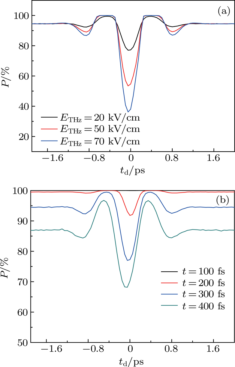
3.2. PL modulation by THz pulse with DC fieldBased on the above analysis, we find that the sampling time and the THz field should exceed their certain thresholds to effectively excite PLQ. Adopting a DC field can make the sampling time threshold shortened and the linear range of THz field-modulation PL expanded. Here we analyze the changes of P value with pulse delay time  under the DC and THz fields. It is supposed that DC field
  , and t = 300 fs (See Fig. 4(a)). Firstly, with the increase of THz peak value, Q peak position declines. While when THz field approaches 0, the equilibrium position of P is 95%, only with the function of DC field. It indicates that the DC field can provide electrons with stable and enduring energy to keep them in the active scattering states, thus overcoming the influence of the threshold effect on the PL response. Secondly, the introduction of the DC field causes the carriers to form directional transport, and the change of external THz field direction leads to the change of carrier transport velocity. In this way, the P value can provide the vibration direction of THz pulse.
Figure 4(b) shows the result from changing t by DC field  and THz field (peak value)
  . It indicates that the shape of P is modulated by the THz field, and the equilibrium position of P in the figure is controlled by the DC field. The degree of quenching by DC field has a direct relationship with time t. As t passes, overall, the P value moves downward. Therefore, it can improve the linear quality of THz field response by controlling t, and search for a larger linear THz field modulation range.
In the above example, we select the smaller outfield ( (see Fig. 4(b)) and backward sampling time t (see Fig. 4(a)). Specific reasons can be analyzed from Fig. 5.
When  , the P value is minimum and the Q value is maximum. Figure 5 shows the changes of Q peak value with sampling time t in different DC fields and THz fields. These changes are different for the linear range, generally, in the time range of 50 fs–400 fs. Unlike figure 3(a), with the increased DC field and relatively small THz field, the time for exceeding the threshold is shortened, and the linear time range is expanded; when the THz field is relatively large, the P value speeds up the decrease with increasing DC field, the PLQ accelerates formation and the linear time range is narrowed down.
In addition, when the time is relatively forward, it needs a larger outfield to overcome the threshold of intervally scattering for good linear modulation; when the time is backward, the carriers accumulate enough energy, thus being prone to causing a nonlinear effect. Then, the smaller outfield can obtain good linear modulation. According to the above results and their analyses, we can select the appropriate sampling time t and outfield.
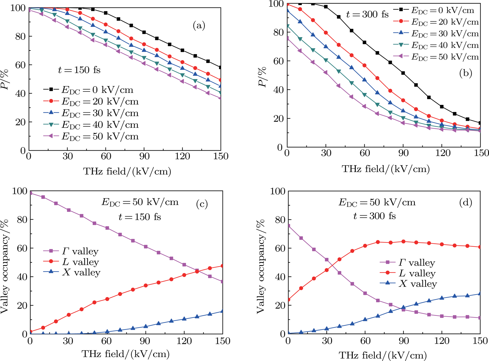
According to Figs. 5(a) and 5(b), we select two time points for comparison. Figures 6(a) and 6(b) show the peaks of Q change with THz fields in different DC fields at t = 150 fs and t = 300 fs, respectively. In these figures the horizontal axes are both THz field intensity. It can be found that the THz field linear range is 50 kV/cm–150 kV/cm at 150 fs without DC field. When DC field is 50 kV/cm, it can directly exceed threshold, so that THz field can be linearly modulated in the range of 0 kV/cm–150 kV/cm. As to the case without a DC field, the linear range is significantly expanded. When the DC electric field continues to increase, the P value decreases with PLQ deepening and starting position declining.
When  fs, the electrons accumulate enough energy, with obvious nonlinearity. When the outfield is high to a certain extent (
 ), the quenching tends to be saturated, no longer having a linear relationship with THz field. With the increase of DC field, the THz field linear modulation range is gradually reduced to the low field direction, and the best value is obtained with a DC field of about 30 kV/cm.
In order to further illustrate different linearities at different time points, we study the electron percentage occupancies in three valleys when  (the purple curve in Figs. 6(a) and 6(b)). Figure 6(c) shows that when the DC field is 50 kV/cm and t = 150 fs, the electrons in L and X valleys account for a certain proportion in a manner similar to linear growth. Then, the electron proportion of
  valley is linear. Compared with the scenario in Fig. 3(b), on the one hand, the DC field here exceeds the electric field threshold; on the other hand, high-energy electrons cause
  –X and L–X scatterings. Due to the forward sampling time, the energy absorptions are relatively uniform for these two scattering mechanisms, resulting in the expansion of the linear range of PLQ to THz intensity. Figure 6(d) shows that when DC field
  , and t = 300 fs, the linear regions of L and X valleys do not synchronize at this time point, exhibiting obvious nonlinear characteristics. Especially when the THz field exceeds 70 kV/cm, the electrons of L valley tend to be saturated, resulting in the electrons of
  valley varying with a nonlinear trend.


