


Comparison between AlN and Al2O3 ceramics applied to barrier dielectric of plasma actuator
Cite this Article
Bian Dong-Liang, Wu Yun, Jia Min, Long Chang-Bai, Jiao Sheng-Bo. Comparison between AlN and Al2O3 ceramics applied to barrier dielectric of plasma actuator. Chinese Physics B, 2017, 26(8): 084703 
Permissions
Comparison between AlN and Al2O3 ceramics applied to barrier dielectric of plasma actuator
† Corresponding author. E-mail:
Project supported by the National Natural Science Foundation of China (Grant Nos. 51522606, 91541120, 51502346, and No.51407194).
Abstract
This paper reports the material characterization and performance evaluation of an AlN ceramic based dielectric barrier discharge (DBD) plasma actuator. A conventional Al2O3 ceramic is also investigated as a control. The plasma images, thermal characteristics and electrical properties of the two actuators are compared and studied. Then, with the same electrical operating parameters (12-kV applied voltage and 11-kHz power frequency), variations of the surface morphologies, consumed power and induced velocities are recorded and analyzed. The experimental results show that the AlN actuator can produce a more uniform discharge while the discharge of the Al2O3 actuator is easier to become filamentary. The later condition leads to higher power consumption and earlier failure due to electrode oxidation. In the plasma process, the power increment of the AlN actuator is higher than that of the Al2O3 actuator. The induced velocity is also influenced by this process. Prior to aging, the maximum induced velocity of the AlN actuator is 4.2 m/s, which is about 40% higher than that of the Al2O3 actuator. After 120-min plasma aging, the maximum velocity of the aged AlN actuator decreases by 27.8% while the Al2O3 actuator registers a decrease of 25%.
1. Introduction
Surface dielectric barrier discharge (SDBD) has been investigated over the past decade in the field of plasma flow control.[1,2] These actuators usually consist of two flat electrodes mounted asymmetrically on either side of a dielectric barrier. When subjected to a high ac voltage applied across the exposed and encapsulated electrodes, the actuator produces an electrically-generated plasma on the surface, where charged species are propelled by the electric field lines colliding with the surrounding air. Comprehensive reviews of physics, experiments and applications of the plasma actuator have been published by Moreau,[3] Corke,[4] Benard and Moreau.[5]
In the past, many papers have studied the properties of various dielectric materials on the performance of DBD plasma actuator. Forte et al.[6] demonstrated that under the same consumed electric power, the induced velocity of a Polymethyl methacrylate (PMMA) plate was higher than that of a glass flat plate. Pons et al.[7] and Dong et al.[8] showed that a decrease of the dielectric thickness led to the increase of maximum induced velocity. However, as the dielectric thickness decreases, the electric discharge is more likely to become filamentary at low applied voltage. In this instance, the discharge filaments usually concentrate at several injection points on the edge of the exposed electrode, which may result in premature dielectric breakdown[6] and may also reduce the efficiency of the plasma actuator.[9] To ensure a more uniform discharge, Thomas et al.[10] and Abe et al.[11] found that a thicker layer of the dielectric resulted in lower dielectric coefficient and higher dielectric strength. Durscher et al.[12] demonstrated that surface temperature of the actuator played a crucial role in the transition from glow discharge to filamentary discharge and the saturation effect can be controlled by changing the local temperature of the dielectric. Furthermore, novel dielectric barrier material[13–15] or material modification[16–18] have also been studied to improve the performance of the DBD actuator. In the area of novel dielectrics, Park et al.[13] demonstrated a flexible DBD reactor, which was composed of copper electrodes and two dielectric layers including water and Teflon tubes. This device produced a stable plasma discharge over a long period of operation due to the cooling of the insulation surface. Durscher and Roy[14] evaluated the performances of two new materials (silica aerogels and ferroelectrics) with extreme permittivity as dielectrics of the actuators, they found that silica aerogels exhibited an order of magnitude in weight ratio of thrust to actuator higher than acrylics. Afterwards, Michael and David[15] used ferroelectric crystal with a large permittivity and small coercive field in an actuator. The applied voltage that was required to generate a discharge and was found to be reduced to 
Layers of Kapton tape, which was comprised of alternative layers of polyimide film and a silicone-based adhesive, are usually used as the dielectric of a plasma actuator.[19,20] Although this approach works, it presents issues relating to discrete thickness, handling difficulties, partial discharge between layers[21] and most significantly, material degradation.[22] Therefore, after long-time plasma process, the top layer of the polyimide film usually degrades then the underlying adhesive appears.[20] Compared with the widely used polymer dielectrics, ceramic offers the advantages of corrosion resistance, high and low temperature resistance, excellent dielectric properties and heat conduction, which make it a good dielectric barrier candidate for the future. For example, after discharge aging, Pons et al.[23] observed very few evidences of degradation on ceramic plates. However, the material properties and performance of the ceramic actuator in the plasma process are still unknown.
In this paper, two different ceramics based DBD plasma actuators are investigated. Firstly, before dielectric aging, plasma images, thermal characteristics and electrical properties of the AlN actuator and the Al2O3 actuator are compared and discussed. Afterwards, the evolutions of the surface morphologies, plasma images, power consumption are monitored and analyzed at various operating times. A Digital microscope imaging system is further used to characterize changes in the surface morphology. Then, the induced velocities of the actuators are measured using a Pitot tube before and after plasma discharge aging.
2. Actuator and experimental apparatus
2.1. Actuator construction
The dielectric barriers used in the plasma actuators are 0.5-mm-thick AlN ceramic and Al2O3 ceramic, which are obtained from Jia Rifeng Electronic Material Co., Ltd (Shenzhen, China). As illustrated in Fig. 
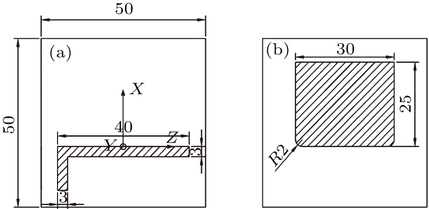 | Fig. 1. Geometry of the DBD plasma actuator: (a) exposed electrode and (b) encapsulated electrode. |
2.2. Experimental apparatus
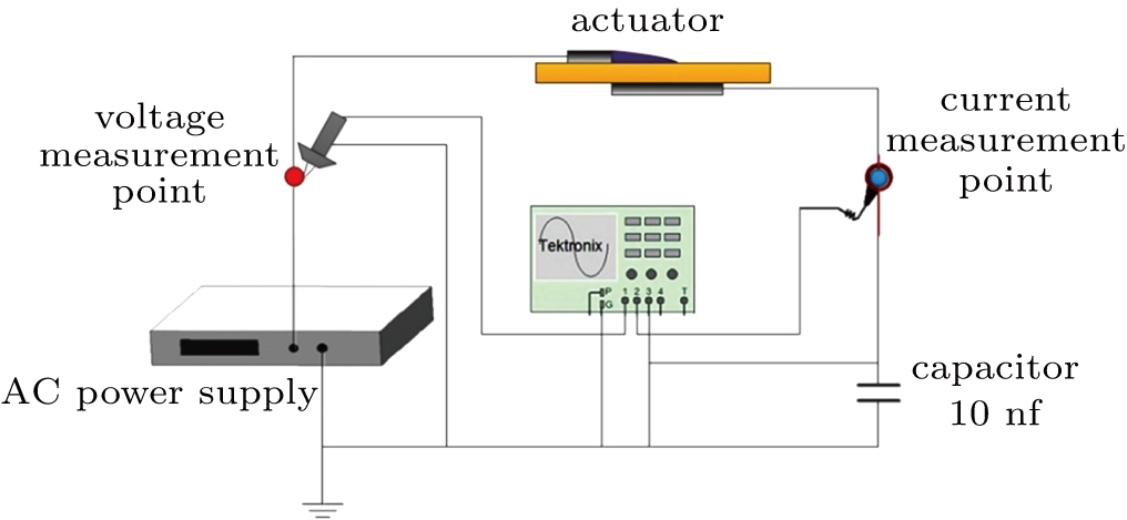
A schematic diagram of the experiment is shown in Fig.
 | Fig. 2. (color online) Schematic diagram of the experiment. |
Surface temperature measurement is conducted using a thermal camera FLIR System (SC7000) in the spectral range of 


A pressure probe made of glass tube (0.5-mm outer bore and 0.3-mm inner bore) is used to measure the induced gas flow. The actuators are mounted on a manual displacement system (Zolix PSA100-11-X) with an accuracy of ±0.1% that permits displacements along three directions. The pressure probe is placed at a distance of 0.05 mm from the dielectric wall. The pressure is measured using a micro differential pressure sensor (K0166), which permits ±10-Pa measurements with an accuracy of ±0.05%. An A/D converter (8 inputs, 10 kS/s, 12 bit) is used to sample the manometer output.
3. Results and analysis
3.1. Plasma images and thermal characteristics
The plasma images are captured using a camera (Nikon D7100), the applied voltage was modified from 6 kV to 15 kV, and the power supply frequency was set to be 11 kHz. As shown in Fig.
 | Fig. 3. (color online) Plasma generated by (a) AlN actuator and (b) Al2O3 actuator, applied voltage amplitude is listed above each image column in unit kV. |
Since the rise in temperature near the edge of the exposed electrode is highest, it can be used as a method to characterize discharge uniformity of the actuator.[24,25] Thus, the surface temperature along the Z direction is further measured by a thermal infrared imager. The actuators are run for a duration of 120 s and then switch off for 30 s. The applied voltages are 8 kV, 10 kV, and 12 kV at a fixed frequency of 11 kHz. The room temperature in this experiment is 17 °C. Figure 

 | Fig. 4. (color online) Spanwise temperature distributions of (a) the AlN actuator and (b) the Al2O3 actuator. |
3.2. Electrical properties
Figure
 | Fig. 5. (color online) Traces of discharge current and applied voltage of (a) AlN actuator and (b) Al2O3 actuator. |
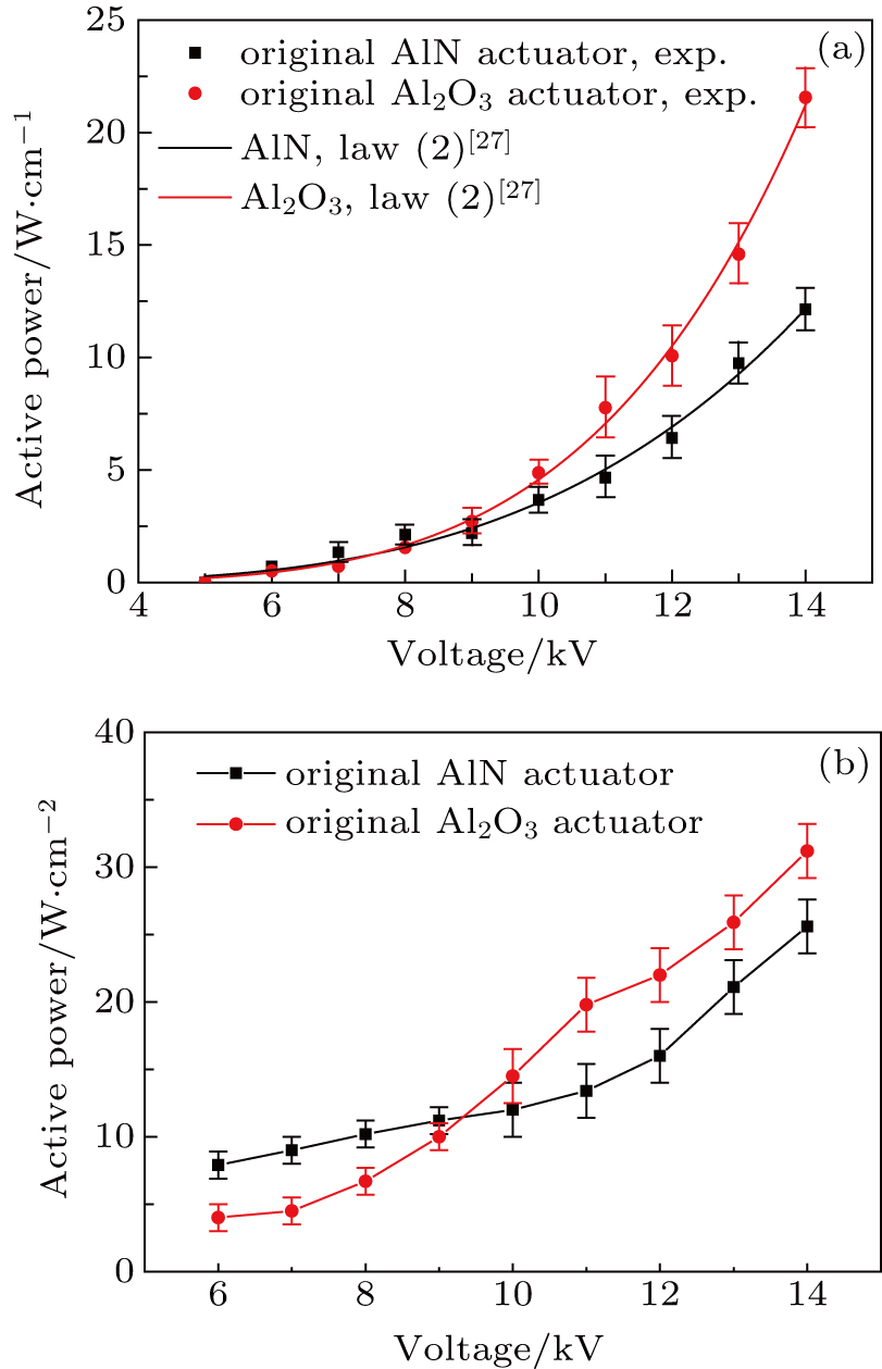
Figure 


 | Fig. 6. (color online) Comparison of plots of active power (a) per unit length and (b) per unit area versus applied voltage between the AlN actuator and the Al2O3 actuator. |
The values of 

| Table 1.
Parameters of the empirical power law ( |
The plots of power per unit area versus applied voltage are given in Fig.
3.3. Surface morphologies and corresponding plasma images
The surface morphologies and corresponding plasma images of the actuators obtained from aging experiments are shown in Fig.
 | Fig. 7. (color online) Surface morphologies and corresponding plasma images of (a) the AlN actuator and (b) the Al2O3 actuator. Operation time is listed above each image column in unit min. |
Figure
 | Fig. 8. (color online) Enlarged surface morphologies around the exposed electrode taken from the surfaces of (a) AlN actuator and (b) Al2O3 actuator. |
3.4. Variation of power consumption after discharge aging
To determine the effects of discharge duration on consumed power, the actuators aged for various times are prepared and their consumed powers are calculated through the Lissajous figures.
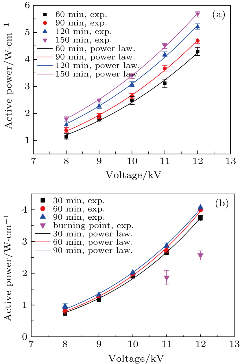
As shown in Fig.
 | Fig. 9. (color online) Variations of active power with applied voltage for (a) AlN actuator and (b) Al2O3 actuator for different discharge times; symbols are related to the experimental data sets; the lines denote the power consumptions obtained from Eq. ( |
As shown in Table
| Table 2.
Parameters of the empirical power law (Eq. ( |
3.5. Induced velocity characteristics
The effects of dielectric aging on the induced velocities of the actuators are investigated through the pressure probe measurements. The values of y distance (vertical height from the upper surface of the actuator dielectric to the lower side of the Pitot tube) are set to be 0.2 mm, 0.5 mm, and 0.8 mm for various conditions. For each measurement, the Pitot tube is placed at a fixed vertical height and moved from x = 0 mm to x = 22.5 mm, at a speed of 0.5 mm/s. Each measurement is repeated 3 times. The time-averaged horizontal component of the ionic wind velocity is obtained from the Bernoulli equation:

The evolutions of velocity for the two actuators are shown in Fig.
 | Fig. 10. (color online) Ionic wind velocities along the X direction of the Al2O3 actuator at (a) 1 min, (b) 60 min, and (c) 120 min and the AlN actuator at (d) 1 min, (e) 60 min, and (f) 120 min. |
The second series of measurements after 60 min of dielectric aging is shown in Figs.
The third series of measurements after 120 min of dielectric aging is shown in Figs.
4. Conclusions
The electrical properties, material characteristics and induced velocities of the DBD plasma actuators with AlN and Al2O3 ceramic dielectrics are experimentally investigated. The main conclusions are as follows.
For the original actuators, either active power per unit length or per unit area, consumed by the Al2O3 actuator is higher than that of the AlN actuator when the applied voltage is greater than 9 kV. The plasma images reveal that long and intense discharge filaments occur in the Al2O3 actuator, but the discharge in the AlN actuator appears more uniformly. This uniformity is further evidenced by surface temperature measurement and current pulse behavior analysis.
For the aged actuators, the two ceramics exhibit different material characteristics. Severe electrode oxidation of the Al2O3 actuator, resulting from intense filaments causes its earlier failure. While for the AlN actuator, the surface is ablated and the traces extend along both the spanwise and streamwise directions as the operation time increases.
The maximum induced velocities of the AlN actuator along the X-direction are higher than those of the Al2O3 actuator at all three y positions (0.2, 0.5, 0.8 mm) before and after dielectric aging. However, long plasma process affects the induced velocities of two actuators. After 120min discharge operation, the maximum velocities of the aged AlN actuator and the Al2O3 actuator decrease by 27.8% and 25%, respectively.
Reference
| [1] | |
| [2] | |
| [3] | |
| [4] | |
| [5] | |
| [6] | |
| [7] | |
| [8] | |
| [9] | |
| [10] | |
| [11] | |
| [12] | |
| [13] | |
| [14] | |
| [15] | |
| [16] | |
| [17] | |
| [18] | |
| [19] | |
| [20] | |
| [21] | |
| [22] | |
| [23] | |
| [24] | |
| [25] | |
| [26] | |
| [27] | |
| [28] | |
| [29] |