Topology optimization using the improved element-free Galerkin method for elasticity
Wu Yi1, Ma Yong-Qi1, 2, Feng Wei1, Cheng Yu-Min1, †
Shanghai Institute of Applied Mathematics and Mechanics, Shanghai University, Shanghai 200072, China
Department of Mechanics, Shanghai University, Shanghai 200444, China


† Corresponding author. E-mail: ymcheng@shu.edu.cn

Project supported by the National Natural Science Foundation of China (Grant Nos. 11571223 and U1433104).

Abstract

The improved element-free Galerkin (IEFG) method of elasticity is used to solve the topology optimization problems. In this method, the improved moving least-squares approximation is used to form the shape function. In a topology optimization process, the entire structure volume is considered as the constraint. From the solid isotropic microstructures with penalization, we select relative node density as a design variable. Then we choose the minimization of compliance to be an objective function, and compute its sensitivity with the adjoint method. The IEFG method in this paper can overcome the disadvantages of the singular matrices that sometimes appear in conventional element-free Galerkin (EFG) method. The central processing unit (CPU) time of each example is given to show that the IEFG method is more efficient than the EFG method under the same precision, and the advantage that the IEFG method does not form singular matrices is also shown.

1. Introduction

Structural optimization design occupies a significant position in science and engineering. As a challenging topic in structural optimization, the topology optimization meets the requirements by redistributing the material under the design constraints.[1]

Bendsoe presented the homogenization method.[1] Inspired by the homogenization method, Bendsoe presented the variable density method.[2] Then he presented the solid isotropic microstructures with penalization (SIMP).[3,4] The 99-line topology optimization code along with the web-based program of Sigmund has a large effect on the promotion of SIMP.[5,6] In 1993, the evolutionary structural optimization was presented based on a discrete variable.[7] In addition, some other new methods, including bubble method, level set method and topology description function, were presented.[8,9]

The finite element method (FEM) is an important method of numerically analyzing the topology optimization of structures. In the topology optimization based on FEM, the regularization methods, including the filtering methods and the projection methods, are proposed to alleviate the gray transition problem.[10,11] However, FEM may have problems like mesh distortion and grid moving when solving large deformation problems, therefore it needs to use re-meshing technique when the computational accuracy cannot be reached.[12,13] For the topology optimization of structures based on large deformation theory, the re-meshing technique in FEM is necessary.

The meshless method, especially the element-free Galerkin (EFG) method, is a kind of challenging numerical method in science and engineering. The EFG method has been applied to many fields, such as elasticity problems of different dimensions, elastodynamics, elastoplasticity, elastic large deformation, plate, shell, fracture, and crack expanding problems.[14,15] It constructs the discrete equations on selected nodes in the problem domain and its boundary. Then it can overcome the mesh dependence and omit the re-meshing process in FEM, and its advantages has been shown.[16,17] The EFG method has been applied to the topology optimization problems.[18,19]

The EFG method is based on the moving least-square (MLS) approximation, which has been proved with high accuracy to obtain the functions.[20] But the final algebraic equation system of the MLS approximation is sometimes ill-conditioned. The shape function of the MLS approximation is more complicated than the one of FEM, the computational efficiency of the EFG method is much lower than FEM, it cannot even obtain a solution sometimes. Then it is important to avoid ill-conditioned or singular algebraic equation systems, and improve the computational efficiency of the EFG method.

The improved MLS (IMLS) approximation was proposed by Cheng Y M and Chen M J to overcome the disadvantages of the MLS approximation method and the corresponding meshless method.[21] The IMLS approximation replaces the normal algebraic basis functions with the weighted orthogonal ones to avoid ill-conditioned equations. In the IMLS approximation, the inverse matrix will not be needed any more, and the solutions can be obtained directly, which results in high computational efficiency. When the node distribution is the same, the efficiency of the IMLS approximation is higher than that of the MLS approximation, which is because IMLS approximation requires fewer nodes in the influence or support domain.[21]

Based on the IMLS approximation, the improved element-free Galerkin (IEFG) method was presented for many problems, such as elasticity, fracture,[22] elastodynamics,[23] transient heat conduction,[24] viscoelasticity,[25] wave equation,[26] and large deformation.[27] Compared with the EFG method, the IEFG method do not form ill-conditioned or singular equations, then the computational efficiency is higher, because the IMLS approximation is used to obtain the shape function. Now the IEFG method has no longer been used for the topology optimization.

Based on the IMLS approximation, the IEFG method for the topology optimization is presented in this paper, and the corresponding formulae are given. The IEFG method in this paper can overcome the disadvantage of the singular matrices that sometimes appear in the EFG method. The CPU time of each example is given to show that the IEFG method is more efficient than the EFG method under the same precision. And it is discussed that when singular matrices appear in the EFG method, the IEFG method in this paper can obtain a correct solution.

2. Improved moving least-square approximation

For function we have where m is the number of the terms of basis functions , and is the coefficient dependent on point .

We can make the basis functions orthogonal based on Gram-Schmidt orthogonalization. For the corresponding orthogonal basis functions are

The corresponding local approximation within the neighborhood of is where is the point in the support domain of .

Let where is the weight function, is a node in the support domain of , n is the number of the nodes, and .

From we have where

When are selected as the weighted orthogonal basis functions, then from Eq. (7) we have where

By substituting Eq. (15) into Eq. (4), we have where

Thus, when equation (7) is solved, it is unnecessary to obtain the inverse of .

From Eq. (17), we know that

With the same node distribution, the efficiency of the IMLS approximation is higher than that of the MLS. As the basis function is not weighted orthogonal in the MLS approximation, the solution of Eq. (13) will be and equation (17) will become Obviously the IMLS approximation does not need to compute the matrix . Then the corresponding computational efficiency of meshless method based on the IMLS approximation will be higher.

From Eq. (14), the solution is obtained directly without using the inverse matrix. The improvement can overcome the disadvantage of singular matrix in the MLS approximation.

3. Improved element-free Galerkin method for topology optimization

In this section, the discrete equations are obtained based on the functional variation, which has the same form as the Galerkin weak form, and are imposed on by the displacement boundary conditions through the penalty method.[28,29]

The equilibrium equation of two-dimensional elasticity is where is the problem domain with boundary , ( ) and represent the stress component and the body force component, respectively.

The corresponding geometric equation is where is the strain component, is the displacement component.

The constitutive equation is where is the matrix of elastic constants.

The boundary conditions are where is the known displacement component on the displacement boundary , is the known traction component on the stress boundary , and is the component of unit outward normal vector on the boundary .

The penalty method is used to add the displacement boundary condition to the equation, then the functional of an elasticity problem is where , and is 0 if the displacement is known in the direction , otherwise it is 1.

Discretizing the solution domain with M nodes and using the IMLS approximation, we have the approximation function of the displacement as then equation (27) will be where andI,J = 1,2,…,M.

From , we have where

According to the basic idea of variable density method, we assume that the range of the relative density of the material is between 0 and 1, and choose the relative node density as the design variable. From the SIMP, which is common in variable density method, we obtain the mathematical model of material as.[24] where is the elastic modulus, is the interpolated elastic modulus, is the design variable, and is the penalization factor.

As the relative density is chosen to be design variable, we construct the relative density field with the shape function of the IMLS approximation as where is the relative density of i-th node, np is the number of nodes which influence the domain covering the point .

Considering the relative density as the design variable, the volume of structure as the constraint, and the minimization of compliance as the objective function of optimization, the model of topology optimization with the IEFG method is[5,6] where is the global displacement vector, and V represent the volumes of all materials in the design domain before and after optimization, and f is the corresponding coefficient. To avoid singularity during the calculation, the lower limit value of relative density is .

Sensitivity of objective compliance will be obtained using the adjoint method.[30]

From Eq. (44), we have then

From Eq. (45) we can obtain then Then equation (46) is rewritten as

From Eq. (49), we can obtain the sensitivity of objective compliance according to the sensitivity of the matrix , then

4. Examples of topology optimization problems

We choose three typical problems as examples to display the correctness and the advantage of IEFG method for topology optimization problems.

As shown in Fig. 1, we consider a cantilever beam, which is clamped on the left edge and a force is applied vertically downward in the middle of the right edge. The size of the beam is 4 m m. The material elastic modulus is E = 30 MPa, and Poisson’s ratio is v = 0.25. The volume coefficient f is 50%.

Fig. 1. A cantilever beam.

Based on the EFG method and IEFG method, 41 × 13 uniformly distributed nodes and 16 × 5 integral cells are used. 4 × 4 points are selected for Gauss integral on a cell. The scaling parameter of the influence domain of nodes is .

The results of topology optimization using different methods, are presented in Figs. 2 and 3. From Figs. 2 and 3, the EFG method and IEFG method obtain the same structures, and no so-called checkerboard appears. The structures shown in Figs. 2 and 3 are clear.

Fig. 2. Result obtained using the EFG method.
Fig. 3. Result obtained using the IEFG method.

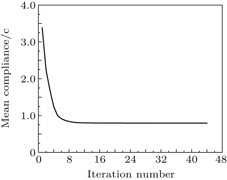
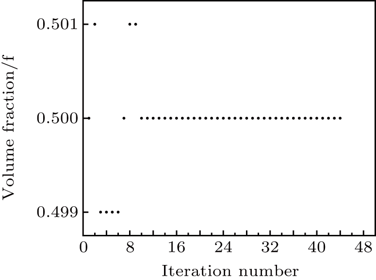
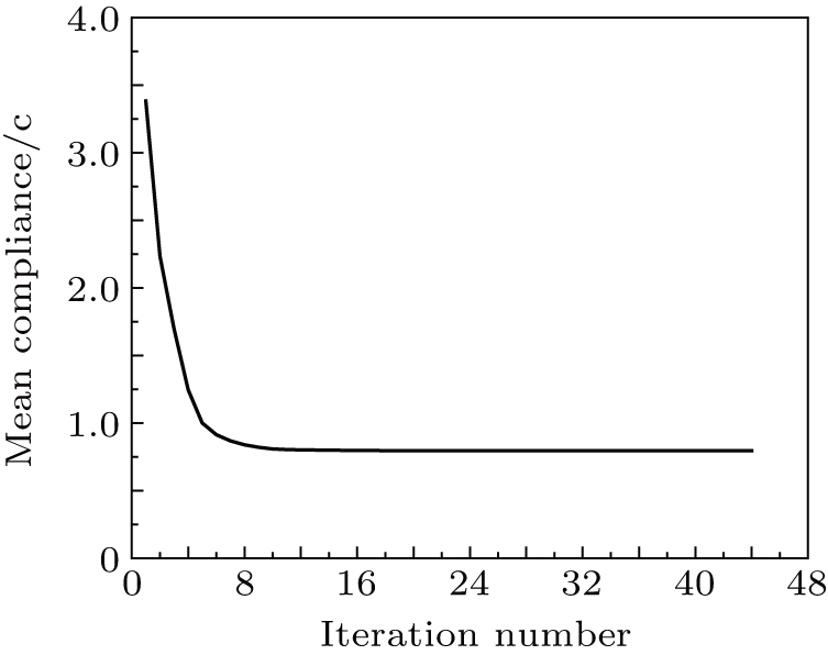
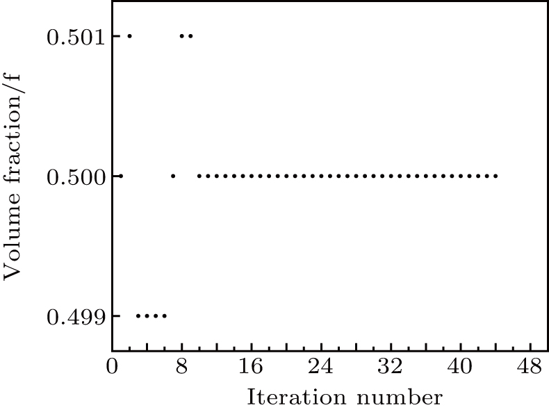
Figures 47 show that the histories of the mean compliance and the volume fractions obtained with the EFG method and the IEFG method are the same. But the topology optimization with the EFG method takes 11222.45 s, and the IEFG method takes 9433.55 s, which means that the IEFG method is 18.96% more efficient than the EFG method.

Fig. 4. History of mean compliance using the EFG method, objective value (mean compliance): .
Fig. 5. History of volume fraction using the EFG method.
Fig. 6. History of mean compliance using the IEFG method, objective value (mean compliance): .
Fig. 7. History of volume fraction using the IEFG method.

Another advantage of the IEFG method over the EFG method is that it never forms a singular matrix in the IMLS approximation. For example, if , when using the EFG method to perform the topology optimization, the computation cannot be done, and ‘Warning: Matrix is singular to working precision’ appears. It is because singular matrices are formed in the MLS approximation. But when the IEFG method is used, the computation can be done, and the result of topology optimization can be obtained (see Fig. 8). Then the IEFG method can overcome the difficulty of singular matrices in the EFG method.

Fig. 8. Result obtained using the IEFG method when .

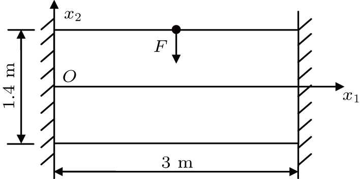
As shown in Fig. 9, we consider a beam, which is clamped on the left and the right ends and a force is exerted in the middle of it. The size of the beam is 3 m × 1 m. The material elastic modulus is E = 30 MPa, and Poisson’s ratio v = 0.25. The volume coefficient f is 50%.

Fig. 9. A clamped beam.

Based on the EFG method and IEFG method, 31 × 15 uniformly distributed nodes and 15 × 4 integral cells are used in the design domain. 4 × 4 points are selected for Gauss integral on a cell. The scaling parameter of the influence domain of nodes is .

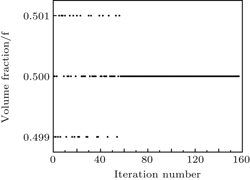
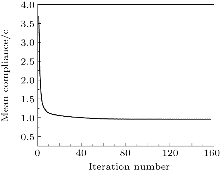
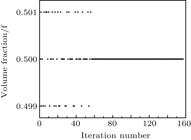
The results of topology optimization using different methods, are presented in Figs. 10 and 11. From Figs. 10 and 10, the EFG method and the IEFG method obtain the same structures, and no so-called checkerboard appears. The structures shown in Figs. 10 and 11 are clear. From Figs. 1215, it can be seen that the histories of the mean compliance and the volume fraction obtained with the EFG method and the IEFG method are the same. The topology optimization using the EFG method takes 2607.65 s, and the IEFG method takes 2118.87 s, which means that the IEFG method is 23.07% more efficient than the EFG method.

Fig. 10. Result obtained using the EFG method.
Fig. 11. Result obtained using the IEFG method.
Fig. 12. History of mean compliance using the EFG method, objective value (mean compliance): .
Fig. 13. History of volume fraction using the EFG method.
Fig. 14. History of mean compliance using the IEFG method, objective value (mean compliance): .
Fig. 15. History of volume fraction using the IEFG method.

Similarly, if , when using the EFG method to perform the topology optimization, the computation cannot be done, and ‘Warning: Matrix is singular to working precision’ appears. The result of topology optimization using the IEFG method is shown in Fig. 16. Again, the IEFG method can overcome the difficulty of singular matrices in the EFG method.

Fig. 16. Result obtained using the IEFG method when .

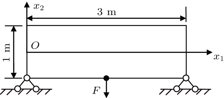
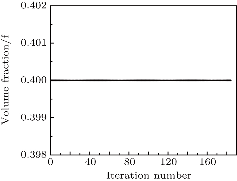
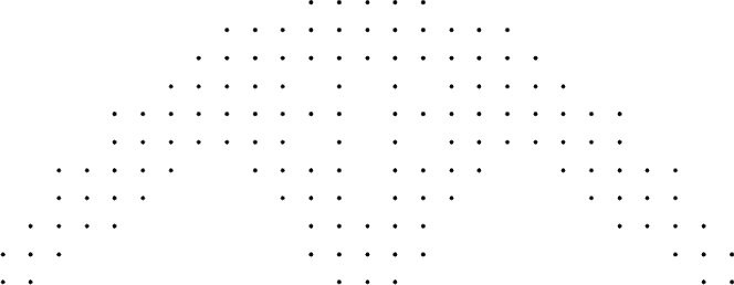
As shown in Fig. 17, we consider a simply supported beam. The size of the beam is 3 m × 1 m. The material elastic modulus is E = 30 MPa, and Poisson’s ratio v = 0.25. The volume coefficient f is 40%.

Fig. 17. A simple support beam.

Based on the EFG method and IEFG method, 31 × 11 uniformly distributed nodes and 15 × 5 integral cells are used in the design domain. 4 × 4 points are selected for Gaussian integral on a cell. The scaling parameter of the influence domain of nodes is .

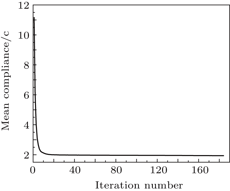
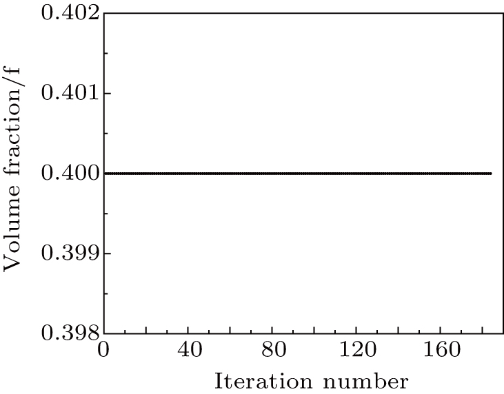
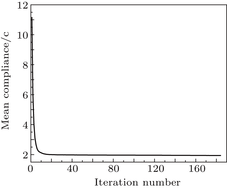
The results of topology optimization using different methods are presented in Figs. 18 and 19. From Figs. 18 and 19, the EFG method and IEFG method obtain the same structures, and no so-called checkerboard appears. The structures shown in Figs. 18 and 19 are clear. From Figs. 2023, it is shown that the histories of the mean compliance and the volume fraction obtained with the EFG method and the IEFG method are the same. The topology optimization using the EFG method takes 9473.10 s, and the IEFG method takes 6914.56 s, which means that the IEFG method is 37% more efficient than the EFG method.

Fig. 18. Result obtained using the EFG method.
Fig. 19. Result obtained using the IEFG method.
Fig. 20. History of mean compliance using the EFG method, objective value (mean compliance): .
Fig. 21. History of volume fraction using the EFG method.
Fig. 22. History of mean compliance using the IEFG method, objective value (mean compliance): .
Fig. 23. History of volume fraction using the IEFG method.

Similarly, if , when using the EFG method to perform the topology optimization, the computation cannot be done, and ‘Warning: Matrix is singular to working precision’ appears. The result of topology optimization using the IEFG method is shown in Fig. 24. Again, the IEFG method can overcome the difficulty of singular matrices in the EFG method.

Fig. 24. Result obtained using the IEFG method when .
5. Conclusions

In this paper, the IEFG method of dealing with the topology optimization problem of structures is presented. By analyzing three problems as example, the advantages of the IEFG method of optimizing the topology of structure are shown.

The optimized structures are clear with definite boundaries and the checkerboard phenomenon disappears.

Furthermore, the topology optimization using the IEFG method is much more efficient than the EFG method. Moreover, the IEFG method can overcome the disadvantages of singular matrices in the EFG method.

Reference
[1] Bendsøe M P 1995 Optimization of structural topology, shape, and material Publication city Springer 10.1007/978-3-662-03115-5
[2] Bendsøe M P 1989 Structural Optimization 1 193
[3] Rietz A 2001 Structural and Multidisciplinary Optimization 21 159
[4] Rozvany G Bendsøe M P Kirsch U 1995 Appl. Mech. Rev. 48 41
[5] Sigmund O 2001 Structural and Multidisciplinary Optimization 21 120
[6] Tcherniak D Sigmund O 2001 Structural and Multidisciplinary Optimization 22 179
[7] Xie Y M Steven G P 1993 Computers & Structures 49 885
[8] De Ruiter M Van Keulen F 2004 Structural and Multidisciplinary Optimization 26 406
[9] Sethian J A Wiegmann A 2000 J. Comput. Phys. 163 489
[10] Sigmund O Petersson J 1998 Structural Optimization 16 68
[11] Noratoa J A Bellb B K Tortorellic D A 2015 Comput. Methods Appl. Mech. Eng. 293 306
[12] Hong W Liu Z S Suo Z G 2009 International Journal of Solids and Structures 46 3282
[13] Li D M Liew K M Cheng Y M 2014 Comput. Mech. 53 1149
[14] Belytschko T Krysl P Krongauz Y 1997 Int. J. Numer. Methods Fluids 24 1253
[15] Lu Y Belytschko T Gu L 1994 Comput. Methods Appl. Mech. Eng. 113 397
[16] Belytschko T Krongauz Y Organ D Fleming M Krysl P 1996 Comput. Methods Appl. Mech. Eng. 139 3
[17] Yagawa G Furukawa T 2000 Int. J. Numer. Methods Eng. 47 1419
[18] Zheng J Long S Y Li G Y 2010 Engineering Analysis with Boundary Elements 34 666
[19] Du Y X Luo Z Tian Q H Chen L P 2009 Engineering Optimization 41 753
[20] Deng Y J Liu C Peng M J Cheng Y M 2015 Int. J. Appl. Mech. 7 1550017
[21] Cheng Y M Chen M J 2003 Acta Mech. Sin. 35 181 in Chinese
[22] Zhang Z Liew K M Cheng Y M Lee Y Y 2008 Engineering Analysis with Boundary Elements 32 241
[23] Zhang Z Hao S Y Liew K M Cheng Y M 2013 Engineering Analysis with Boundary Elements 37 1576
[24] Zhang Z Wang J F Cheng Y M Liew K M 2013 Sci. China-Phys. Mech. Astron. 56 1568
[25] Peng M J Li R X Cheng Y M 2014 Engineering Analysis with Boundary Elements 40 104
[26] Zhang Z Li D M Cheng Y M Liew K M 2012 Acta Mech. Sin. 28 808
[27] Cheng Y M Bai F N Liu C Peng M J 2016 Int. J. Comput. Mater. Sci. Eng. 5 1650023
[28] Peng M J Liu P Cheng Y M 2009 Int. J. Appl. Mech. 1 367
[29] Sun F X Wang J F Cheng Y M 2016 Int. J. Appl. Mech. 8 1650096
[30] Zheng J Yang X J Long S Y 2015 Int. J. Mech. Mater. Design 11 231