Bridge-free fabrication process for Al/AlOx/Al Josephson junctions
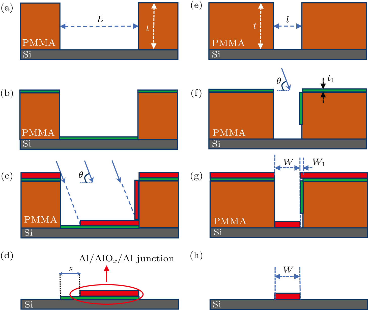
(color online) (a)–(d) Film evaporation in the junction area (the cross section marked with the blue dashed line in Fig.

Bridge-free fabrication process for Al/AlOx/Al Josephson junctions |
|
(color online) (a)–(d) Film evaporation in the junction area (the cross section marked with the blue dashed line in Fig. |
 |