† Corresponding author. E-mail:
A series of Ni0.6−x/2Zn0.4−x/2SnxFe2O4 (x = 0.0, 0.05, 0.1, 0.15, 0.2, and 0.3) (NZSFO) ferrite composities have been synthesized from nano powders using a standard solid state reaction technique. The spinel cubic structure of the investigated samples has been confirmed by x-ray diffraction (XRD). The magnetic properties such as saturation magnetization (


Over the last few decades, the scientific community has paid significant attention to the spinel ferrites due to their fascinating properties that meet the requirements of various applications. No other magnetic materials can replace the ferrites due to their low price, availability, and stability. The Ni–Zn ferrites have become an important candidate in high frequency applications due to their high electrical resistivity, high permeability, compositional stability, and low eddy current losses.[1–6] The uniqueness of the Ni–Zn ferrites is motivating numerous researchers to open the way for commercial applications and new types of ferrites are unveiled with excellent properties for practical application. The properties of the Ni–Zn ferrites can be tailored by altering the chemical composition, preparation methods, sintering temperature (
The properties of the Ni–Zn ferrites can be changed remarkably by substitution of tetravalent ions such as Ti4+ and Sn4+. Investigations on the substitution of Sn4+ have been reported by many researchers.[6,9–11] We reported the structural, morphological, and electrical properties of Sn-substituted Ni–Zn ferrites.[6] Das et al. reported the variation of the lattice parameter, saturation magnetization, and Curie temperature with Ti4+, Zr4+, and Sn4+ substitution in Ni–Zn ferrites synthesized by the chemical method.[9] The Sn4+ substituted Ni 
To the best of our knowledge, the study of Ni–Zn ferrites prepared from nano powders has not been reported yet. Here, we report the magnetic properties of Sn-substituted Ni0.6Zn0.4Fe2O4 ferrites prepared from nano-sized raw materials by the solid state reaction technique.
A solid state reaction route was followed to synthesize Sn substituted Ni–Zn ferrite 


The XRD patterns of the Sn-substituted Ni–Zn ferrites Ni0.6−x/2Zn0.4−x/2SnxFe2O4 are shown in Fig.
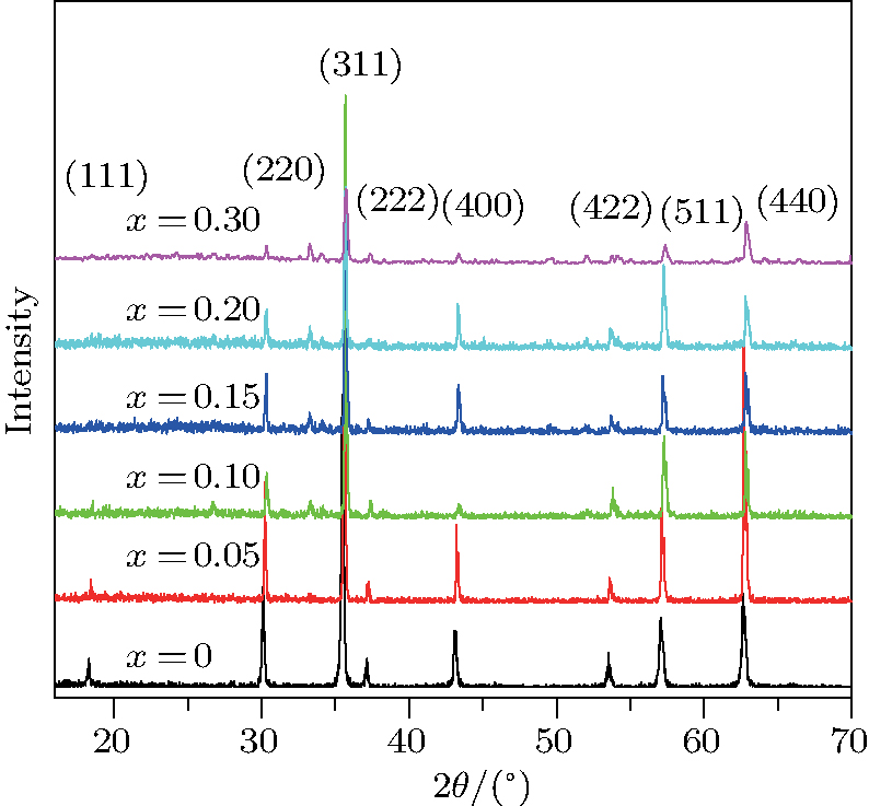 | Fig. 1. (color online) XRD patterns of Ni0.6−x/2Zn0.4−x/2SnxFe2O4 (x = 0.0, 0.05, 0.1, 0.15, 0.2 0.3, and 0.4).[6] |
| Table 1.
The lattice constant |
The distances between the magnetic ions at tetrahedral (A) and octahedral (B) sites are calculated using the equations 


The plots of applied magnetic field H (up to 10 kOe) dependent magnetization at room temperature of Ni0.6−x/2Zn0.4−x/2SnxFe2O4 (x = 0.0, 0.05, 0.1, 0.15, 0.2, and 0.3) ceramics sintered at 1300 °C are shown in Fig.
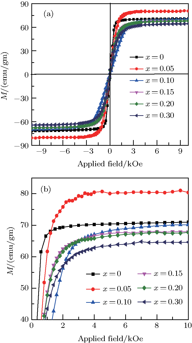 | Fig. 2. (color online) (a) The M–H loops of the NZSFO ferrite samples, (b) magnification of the upper saturated part of the M–H loops. |
The magnetization increases with increasing the applied magnetic field up to a certain field above which the sample becomes saturated. The saturation magnetization 


The variation of saturation magnetization 


It is assumed that the Sn ions occupy tetrahedral (A) sites initially at lower Sn concentrations however, they reside in B sites at higher Sn concentrations, leading to the reduction of A–A interactions. Consequently, the net magnetic moment, 


The Sn content dependence of the coercive field of NZSFO is depicted in Table 


In general, the 


The porosity of the NZSFO increases almost linearly with Sn concentration (approx. 27%–34%) while the porosity for the NZFO is of around 19%.[6] The grains size of the prepared samples (Table 


The values of 


Figure 


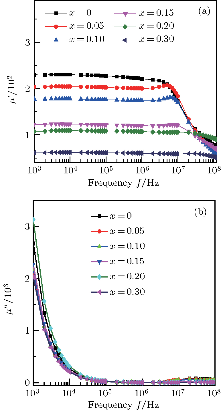 | Fig. 3. (color online) The frequency dependence of permeability of the NZSFO with different Sn concentrations: (a) real part, (b) imaginary part. |
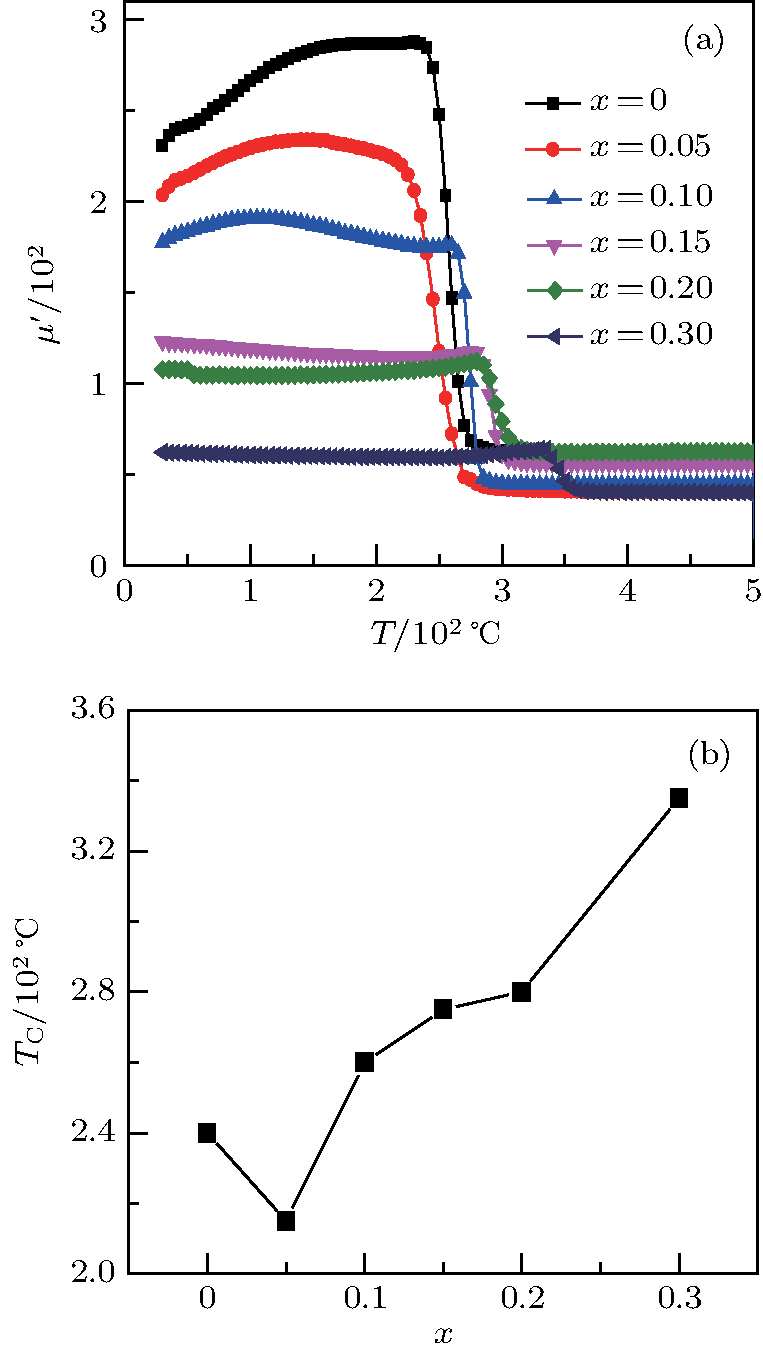
Variation of 


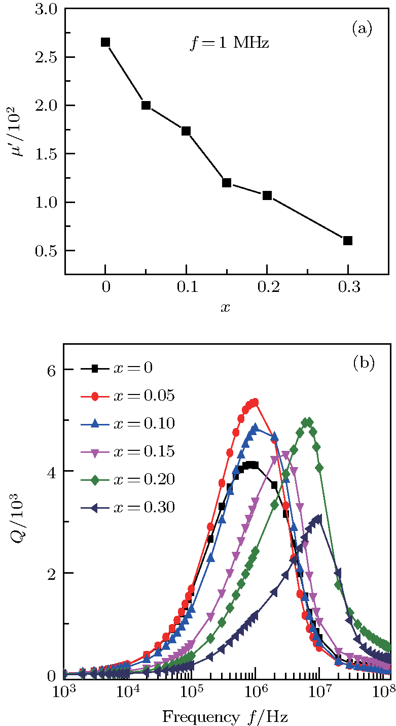 | Fig. 4. (color online) Variation of (a)  |
Curie temperature 


It can be explained as follows. Initially, the dopant cations are assumed to occupy tetrahedral (A) sites and they enter into B sites due to further increase of dopant cations thereby pushing some Fe3+ ions to A-sites, resulting in the magnetic ion density decrease in the B sub-lattice.[9] The increase of the magnetic ions in the A sites increases the A–B interaction, consequently increasing the 

Finally, from Table 

Sn-substituted polycrystalline ferrites, NZSFO (x = 0.0, 0.05, 0.1, 0.15, 0.2, and 0.3) sintered at 1300 °C, have been successfully synthesized using standard ceramic technique. The single phase spinel structure of the samples has been confirmed by the XRD patterns. The grain size increases from 


The authors are grateful to the Directorate of Research and Extension, Chittagong University of Engineering and Technology (CUET), Chittagong-4349, Bangladesh under grant number CUET/DRE/201415/PHY/002 for arranging the financial support for this work. We are also thankful for the laboratory support of the Materials Science Division, Atomic Energy Commission, Dhaka 1000, Bangladesh.
| [1] | |
| [2] | |
| [3] | |
| [4] | |
| [5] | |
| [6] | |
| [7] | |
| [8] | |
| [9] | |
| [10] | |
| [11] | |
| [12] | |
| [13] | |
| [14] | |
| [15] | |
| [16] | |
| [17] | |
| [18] | |
| [19] | |
| [20] | |
| [21] | |
| [22] | |
| [23] | |
| [24] | |
| [25] | |
| [26] | |
| [27] | |
| [28] | |
| [29] | |
| [30] | |
| [31] | |
| [32] | |
| [33] | |
| [34] | |
| [35] |


