Asymmetrical mirror optimization for a 140 GHz TE22,6 quasi-optical mode converter system
Xia Dong1, Jin Ming1, 2, Bai Ming1, †
School of Electronics and Information Engineering, Beihang University, Beijing 100191, China
Institute of Remote Sensing and Digital Earth, State Key Laboratory of Remote Sensing, Beijing 100101, China


† Corresponding author. E-mail: mbai@buaa.edu.cn

Abstract

We introduce an asymmetrical mirror design to a 140 GHz TE22,6 quasi-optical (QO) mode converter system to correct the asymmetry of the beam’s field distribution caused by the Denisov launcher. By such optimization, the output beam with better symmetrical distribution is obtained at the system’s output window. Based on the calculated results, the QO mode converter system’s performance is already satisfying without iterative phase correction. Scalar and vector correlation coefficients between the output beam and the fundamental Gaussian beam are respectively 98.4% and 93.0%, while the total power transmission efficiency of the converter system is 94.4%. The assistance of optical ray tracing to the design of such QO mode converters is introduced and discussed as well.

1. Introduction

Gyrotrons are high-power microwave sources working in the millimeter and submillimeter wave bands.[1,2] Output electromagnetic (EM) waves of gyrotrons are normally in high-order cylindrical cavity modes, which are not suitable for direct utilization.[3] Therefore, quasi-optical (QO) mode converter systems are introduced to convert the high-order cavity modes of EM waves from gyrotrons into the fundamental Gaussian mode for further applications.[48] A typical QO mode converter consists of a waveguide launcher and a mirror system. The Denisov launcher[7] is used to preliminarily convert the high-order cylindrical cavity mode into the approximately fundamental Gaussian mode with its pre-shaped effect, while the mirror system converts the wave from the launcher into a highly pure Gaussian-like output beam.[8]

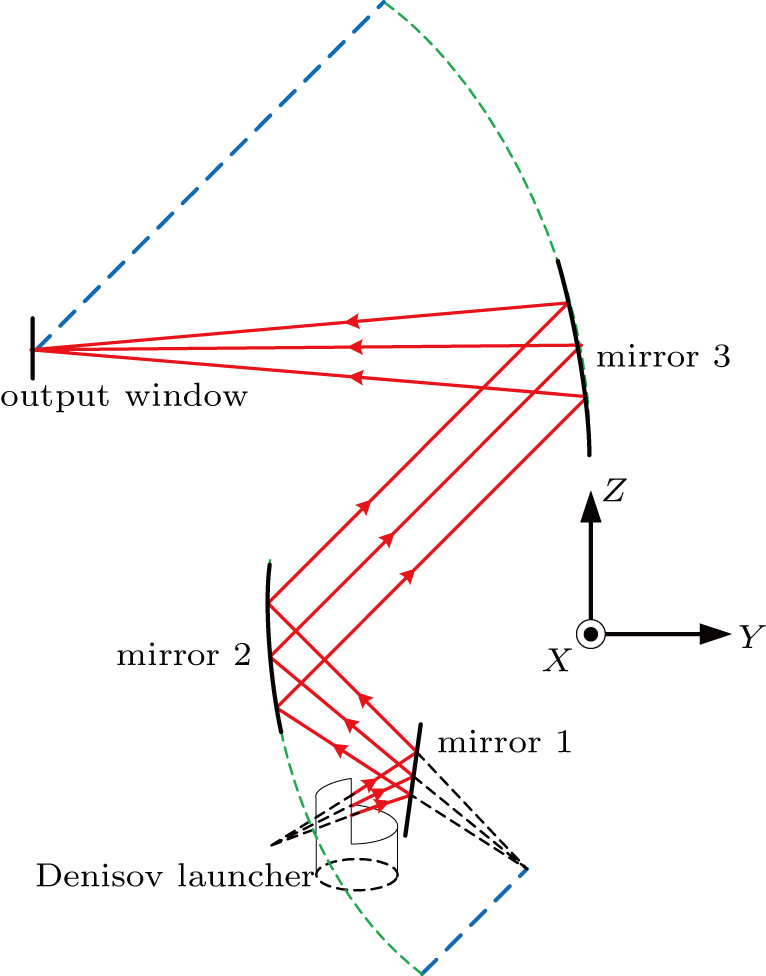
For a typical Denisov launcher, the radiated beam has a Gaussian-like but deformed distribution which requires both amplitude and phase optimization by the mirror system so that an output beam with desired Gaussian-like field distribution can be obtained. To eliminate the deviation between the field distributions of the output beam and the Gaussian mode, iterative algorithms for mirror optimization, such as the Katsenelenbaum–Semenov algorithm (KSA),[9,10] are widely adopted. The essential idea of KSA is utilizing mirror deformation to create optical path difference, which in turn changes the original phase distribution of the beam. Along with multi rounds of mirror optimization, the phase error between the distributions of the output beam and the Gaussian beam can be minimized. However, owing to its basic mechanism, KSA is inadequate in optimizing the large scale of asymmetrical amplitude distribution caused by the launcher’s structural asymmetry. To such kind of beam distortion, we propose a feasible approach that rectifies the field distribution during the beam-shaping process. A 140 GHz TE22,6 QO mode converter system is given in this paper, as shown in Fig. 1. Mirror 1 is a quasi-elliptical mirror which preliminarily converges the beam from the Denisov launcher, while mirror 2 and mirror 3 are asymmetrically designed to correct the beam’s asymmetrical distribution caused by the launcher. By such an asymmetrical optimization, the output beam at the output window plane has a symmetrical contour of radiation field.

Fig. 1. (color online) Scheme of QO mode converter for the 140 GHz, TE22,6 mode gyrotron.

In this paper, we discuss both design and optimization of the 140 GHz TE22,6 QO mode converter system assisted with optical ray tracing and confirmed by full-wave EM calculation. Section 2 gives the design of the Denisov launcher. The optimized mirror system (including two asymmetrical mirrors) is given in Section 3. Section 4 gives output beam’s field distribution of the optimized converter system, followed by a conclusion in Section 5.

2. Design of Denisov launcher

Based on the coupled-mode theory, a Denisov launcher is designed with helical perturbation in the launcher wall surface.[1113] The designed perturbation turns the waveguide eigenmode into a mixture of nine modes in order to approximate the Gaussian field distribution. The radius of the waveguide wall with perturbation is described by

where ϕ is the azimuthal coordinate and z is the axial coordinate of the launcher. a represents the radius of the launcher. δ1 and δ2 are the perturbation amplitudes and β is the propagation constant of the cylindrical cavity mode.

For a 140 GHz TE22,6 mode gyrotron with waveguide radius a = 16.8 mm, the amplitudes of the launcher wall perturbations are equal to δ1 = 0.058 mm and δ2 = 0.047 mm, which is shown in Fig. 2(a). The power variation of mode composition along Z axis is given in Fig. 2(b). Pure TE22,6 mode (100%) power is injected into the waveguide at the beginning of the launcher (z = 0). With the deformation of the waveguide wall, part of TE22,6 mode power is gradually coupled into its satellite modes. There are four modes which have strong couplings with the TE22,6 mode: TE23,6, TE21,6, TE19,7, and TE25,5. This agrees well with the prediction of the coupled-mode theory.
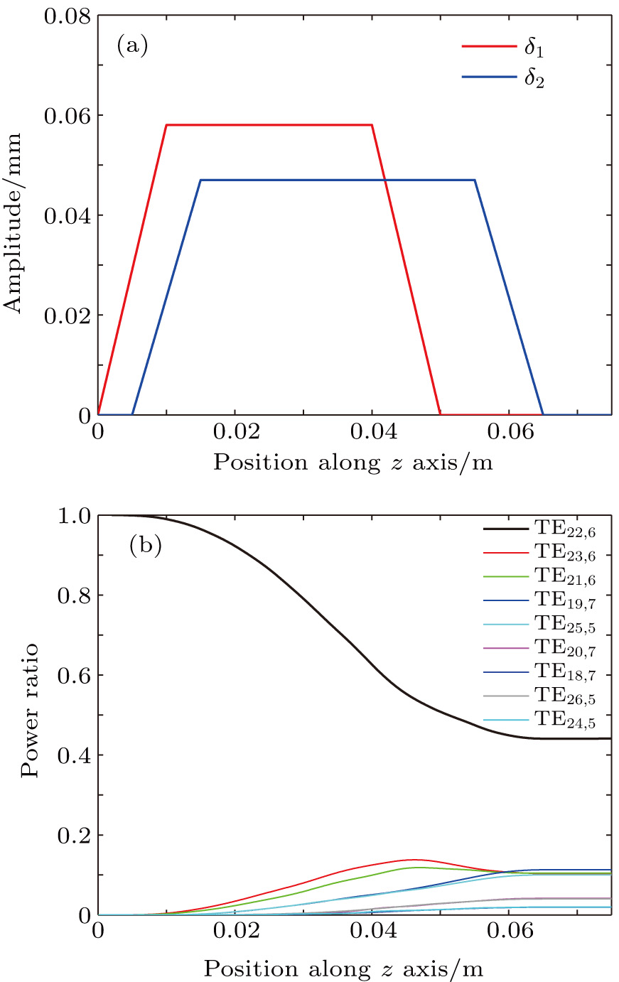
Fig. 2. (color online) (a) Wall deformation of Denisov launcher and (b) power variation of mode composition along Z axis.

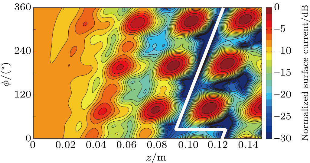
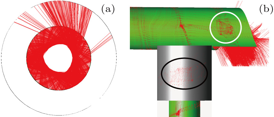
Figure 3 gives the calculated surface current distribution of the unrolled launcher wall. The launcher’s cutting edge is located at the position where a fine Gaussian-like distribution is formed with low sidelobe (see the white line in Fig. 3). For the Denisov launcher with operating frequency around 140 GHz, it should be interesting and informative to take a look at the pre-shaping process in the launcher with geometric optics. As shown in Fig. 4, optical ray tracing is performed starting from the Denisov launcher. The similarity between the results of ray tracing and EM calculation (see Fig. 3) is surprisingly good although some details differ. The rays do not strictly remain tangential to the caustic circle because of the wall perturbation, which is shown in Fig. 4(a). By the ray tracing method, the beam shaping process along the waveguide wall is well revealed with Gaussian-like beam formed (interior of white circle in Fig. 4(b)) and launched from the helical cut (interior of black circle in Fig. 4(b)). The results also show that the output beam from the Denisov launcher is already Gaussian-like but deformed.

Fig. 3. (color online) Field distribution of the unrolled launcher wall by EM calculation.
Fig. 4. (color online) Denisov launcher’s ray tracing results from top view (a) and side view (b).
3. Mirror system with asymmetrical design

The function of the mirror system concentrates on beam-shaping transformation which converts the beam from the waveguide launcher to an output beam with desired field distribution. Compared with the Vlasov launcher, the beam radiated by the Denisov launcher has an apparent divergent trend. This mirror system is specifically designed with a quasi-elliptical mirror (mirror 1) and two asymmetrical mirrors (mirror 2 and mirror 3). Mirror 1 focuses the beam preliminarily, while mirror 2 and mirror 3 converge the beam to the output window and correct the asymmetry of the beam’s distribution with their asymmetrical shapes.

Mirror 1 has a quasi-elliptical transverse cutting profile which focuses the beam from the caustic circle tangentially (shown in Fig. 5(a)). To verify the beam path design of mirror 1, ray tracing is performed and the rays are well focused in the vicinity of the focal point, as shown in Fig. 5(b). Mirror 1 is set to lean outward to make the converter system more compact.
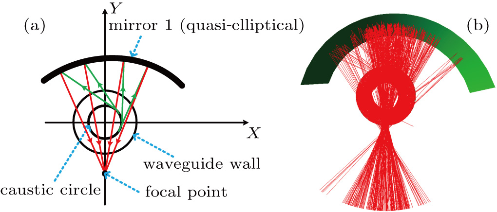
Fig. 5. (color online) (a) Cross section of quasi-elliptical mirror 1 and (b) the corresponding ray tracing result.

With functions of converging beam as well as optimizing its asymmetrical field distribution, mirror 2 and mirror 3 are designed together as a group. By sweeping part of an ellipse along the given path of a parabola, these two mirrors are preliminarily formed. The longitudinal cutting lines of mirror 2 and mirror 3 are parabolas which are depicted in Fig. 1 together with the whole system’s beam path. Therefore, mirror 2 turns the divergent beam into a parallel beam longitudinally, and mirror 3 focuses the beam to the output window. The tangential cutting lines of mirror 2 and mirror 3 are elliptical so that the beam is focused independently and tangentially. Ray tracing of the whole QO mode converter system is performed to verify the system’s design. The ray tracing result, including ray distributions of three mirrors, is given in Fig. 6.
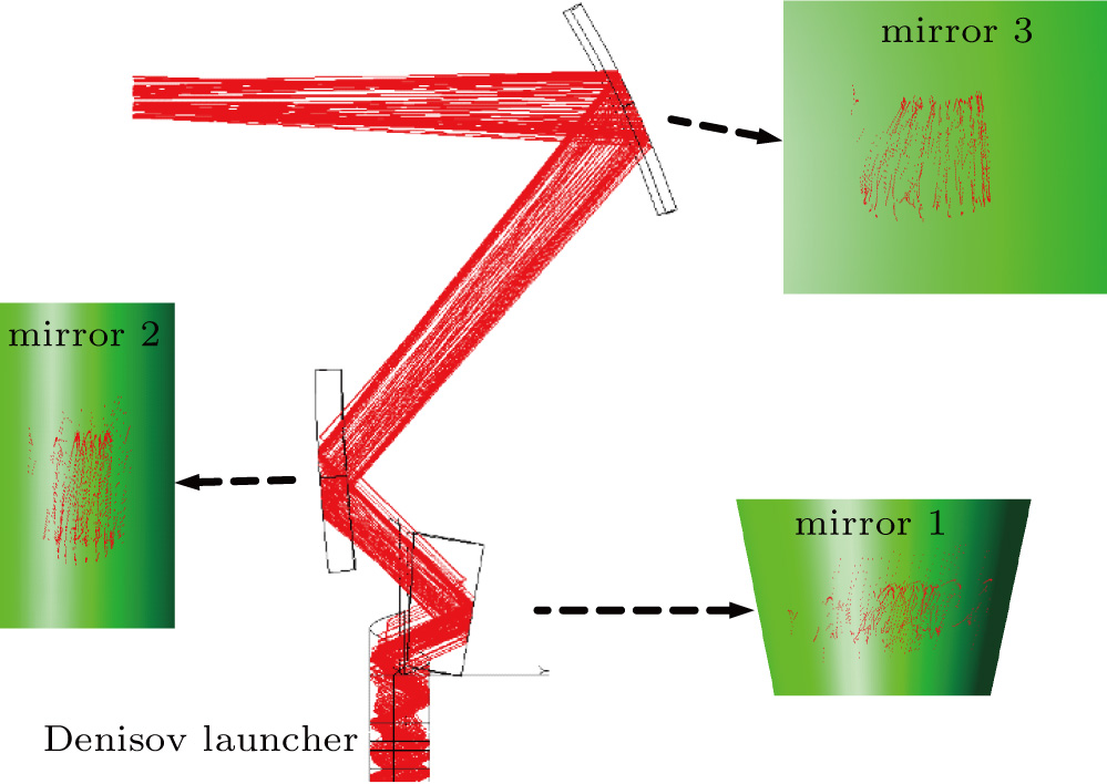
Fig. 6. (color online) Optical ray tracing result for the QO mode converter system (including ray distributions of three mirrors).

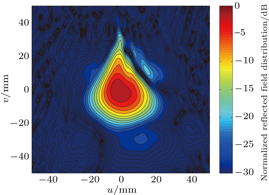
As shown in Figs. 3 and 4, the radiated beam’s asymmetrical amplitude distribution mainly originates from the perturbation along the waveguide wall of the Denisov launcher. After it is reflected and converged by mirror 1, the beam remains asymmetrical, as given in Fig. 7 by EM calculation.

Fig. 7. (color online) Reflected field of the quasi-elliptical mirror 1 by EM calculation.

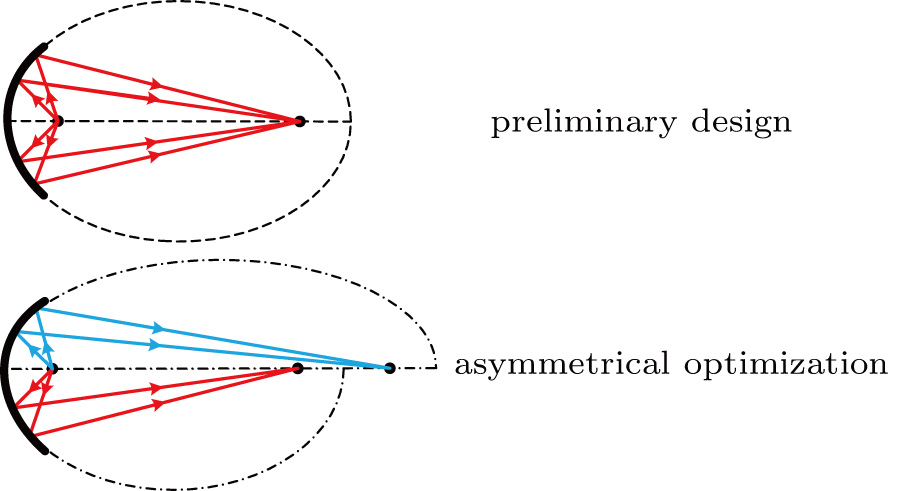
With the hope of correcting the asymmetry of the output wave’s field distribution, asymmetrical optimization is introduced to mirror 2 and mirror 3. As shown in Fig. 8, the tangentially elliptical cutting profiles of mirror 2 and mirror 3 are reset to bilaterally asymmetric. Two different semi-ellipses with one common focal point are combined to form a new asymmetrical curve. This structured asymmetrical curve is still smooth with continuous first derivative at the junction. By optical ray analysis, unlike the previous elliptical design which focuses rays from one focal point to the other, the modified design focuses two parts of the rays to two slightly different focal points. Therefore, such designed mirrors converge two parts of the beam by different extents. In this way, we can operate targeted correction on the beam’s asymmetrical distribution with extra flexibility.

Fig. 8. (color online) Scheme of asymmetrical optimization for mirror 2 and mirror 3.

Take mirror 2 for example, to correct the bilaterally asymmetrical reflected field distribution (shown in Fig. 9(a)), the left side of mirror 2 should be reconstructed with larger curvature. In practice, we perform such optimization by adjusting the ratio of two semi-ellipses’ focal lengths. After we introduce asymmetrical optimization to mirror 2, the deformed left half of the reflected field is noticeably corrected, as shown in Fig. 9(b). In this way, better symmetry of the amplitude distribution is obtained.
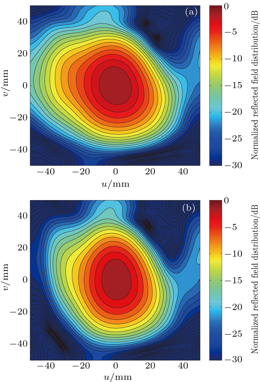
Fig. 9. (color online) Comparison between (a) original and (b) asymmetrically optimized reflected field distributions of mirror 2.

A similar optimization is brought to mirror 3, which is shown in Fig. 10. After optimization, we obtain better symmetrical reflected field of mirror 3 at the output window compared with the original design. By comparing the optimized mirrors’ reflected fields with the original mirrors’ reflected fields, the effectiveness of the asymmetrical mirror optimization is verified.
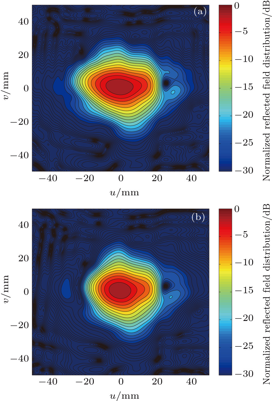
Fig. 10. (color online) Comparison between (a) original and (b) asymmetrically optimized reflected field distributions of mirror 3 at the output window.

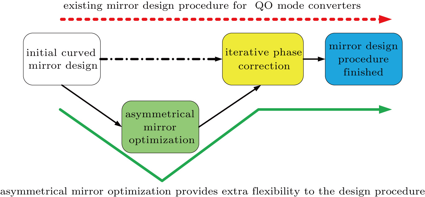
As given in Fig. 11, the asymmetrical mirror optimization method can be considered as a valuable supplement to the existing design procedure of QO mode converter’s mirror system. Compared with the initially designed mirrors, the asymmetrically optimized mirrors have Gaussian-like reflected field distributions with better symmetry, which provides better starting contours for further iterative phase correction. Therefore, performance of QO mode converters can be improved with the asymmetrical mirror optimization method.

Fig. 11. (color online) Diagram of asymmetrical optimization along with the existing mirror design procedure.
4. Calculated results and discussion

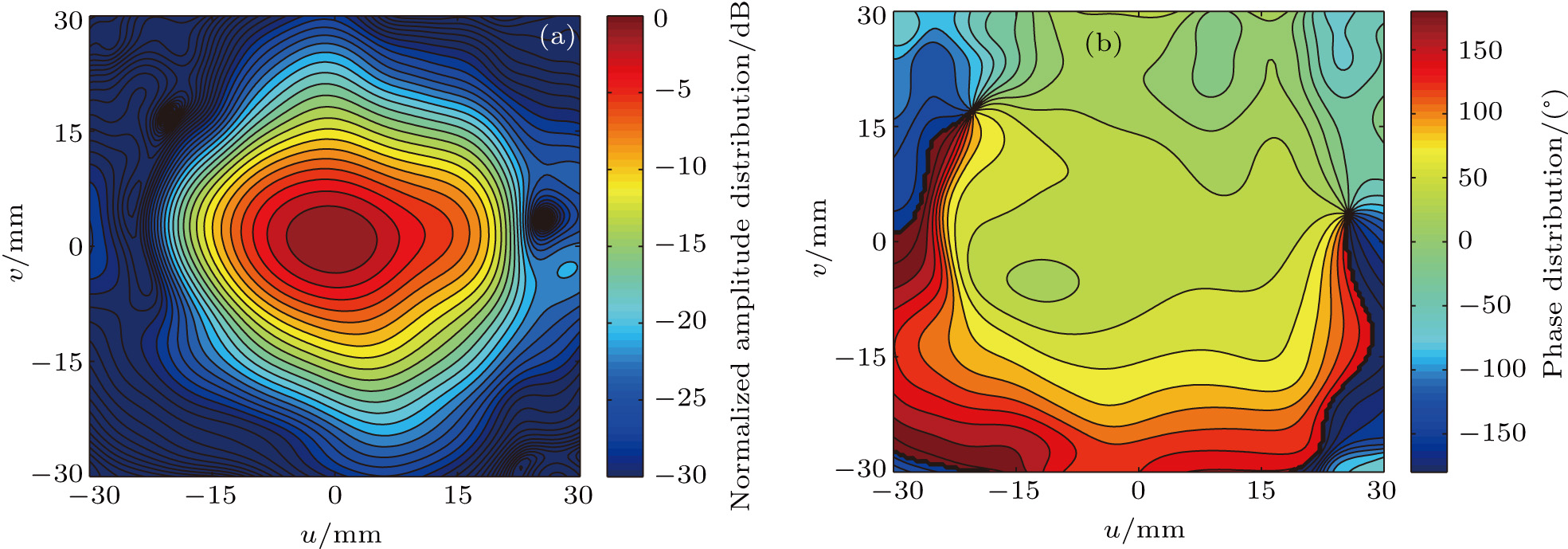
After asymmetrical optimization mentioned above, full-wave EM calculation is performed for the 140-GHz TE22,6 QO mode converter system. The output beam is well focused at the window plane with more symmetrical Gaussian-like distribution. The amplitude and phase distributions at the output window are respectively given by Figs. 12(a) and 12(b) with contour lines, which reveals that the phase distribution around the beam center is fairly flat.

Fig. 12. (color online) (a) Amplitude and (b) phase distributions of the output beam.

Scalar correlation coefficient ηs and vector correlation coefficient ηv are used[14,15] to demonstrate the agreement between the distributions of the output beam and the fundamental Gaussian beam

where u1 represents the output beam distribution with phase distribution φ1, while u2 is the fundamental Gaussian distribution with phase distribution φ2. By calculation, the designed converter system has a scalar correlation coefficient ηs = 98.4% and a vector correlation coefficient ηv = 93.0%.

The power transmission efficiency of the converter system is defined by

where is the injected power and is the power which goes across the output window plane.[10] The power transmission efficiency of this QO mode converter system is P = 94.4% and the Gaussian conversion efficiency of the optimized system is 87.8% ().

To highlight the optimization effect of the asymmetrical mirror design, iterative phase correction for the mirror system is not given in this paper, which means that this asymmetrically optimized 140 GHz TE22,6 QO mode converter system still has room for improvement with phase correcting techniques. Meanwhile, it has been demonstrated that the optical ray tracing technique can be used as an assistant tool for designing such high-frequency QO mode converters. There are good similarities between ray tracing and EM calculation when analyzing the beam path or field distribution. Despite its lack of accuracy, ray tracing is simple, revealing, and fast compared with EM calculation. The design schedule of the system can be accelerated with the assistance of both optical ray tracing and full-wave EM calculation.

5. Conclusion

A QO mode converter system for a 140 GHz, TE22,6 mode gyrotron is designed with the coupled-mode theory and optical ray tracing. An asymmetrical mirror design is introduced to optimize the asymmetrical field distribution of the beam from the Denisov launcher. A Gaussian conversion efficiency of 87.8% has been achieved for the optimized system which converts a TE22,6 cylindrical cavity mode into Gaussian mode. The output beam of the optimized converter system has better symmetrical Gaussian distribution with vector correlation coefficient up to ηv = 93.0% without iterative phase correction. During design procedure, we demonstrate that the optical ray tracing technique can be beneficial to designing such high frequency QO mode converters, even with the Denisov launcher working at high-order cavity modes.

Reference
[1] Nusinovich G S Thumm M K A Petelin M I 2014 J. Infrared Millim. Terahertz Waves 35 325
[2] Fu W Guan X Chen C Li X 2014 IEEE Trans. Electron Devices 61 2531
[3] Cairns R A Phelps A D R 1997 Generation and Application of High Power Microwaves New York CRC Press 121 171
[4] Denisov G G Kuftin A N Malygin V I Venediktov N P Vinogradov D V Zapevalov V E 1992 Int. J. electronics 72 1079
[5] Liu D Wang W Zhuang Q Yan Y 2015 IEEE Electron Device Lett. 36 195
[6] Rock B Y Fliflet A W 2013 IEEE Trans. Terahertz Sci. Tech. 3 641
[7] Bogdashov A A Denisov G G 2004 Radiophys. Quantum Electron. 47 283
[8] Prinz H O Arnold A Dammertz G Thumm M 2007 IEEE Trans. Microw. Theory Tech. 55 1697
[9] Katsenel B Z Semenov V V 1967 Radio Eng. Electron. Phys. 12 223
[10] Liu J Jin J Thumm M Jelonnek J Li H Zhao Q 2013 IEEE Trans. Plasma Sci. 41 2489
[11] Wu Z W Li H Xu J H Li T M Li J Y 2014 Chin. Phys. B. 23 059201
[12] Thumm M Yang X Arnold A Dammertz G Michel G Pretterebner J Wagner D 2005 IEEE Trans. Electron Devices 52 818
[13] Wang W Liu D Qiao S Liu S 2014 IEEE Trans. Plasma Sci. 42 346
[14] Qu J Xue C Pan W Chen X Yu C Shi M Chen S 2012 High Power Laser & Particle Beams 24 157
[15] Jin J Piosczyk B Thumm M Rzesnicki T 2006 IEEE Trans. Plasma Sci. 34 1508