Different angle-resolved polarization configurations of Raman spectroscopy: A case on the basal and edge plane of two-dimensional materials*
Project supported by the National Key Research and Development Program of China (Grant No. 2016YFA0301204) and the National Natural Science Foundation of China (Grant Nos. 11604326, 11434010, 11474277, and 11225421).
Liu Xue-Lu1, 2, Zhang Xin1, 2, Lin Miao-Ling1, 2, Tan Ping-Heng1, 2, †
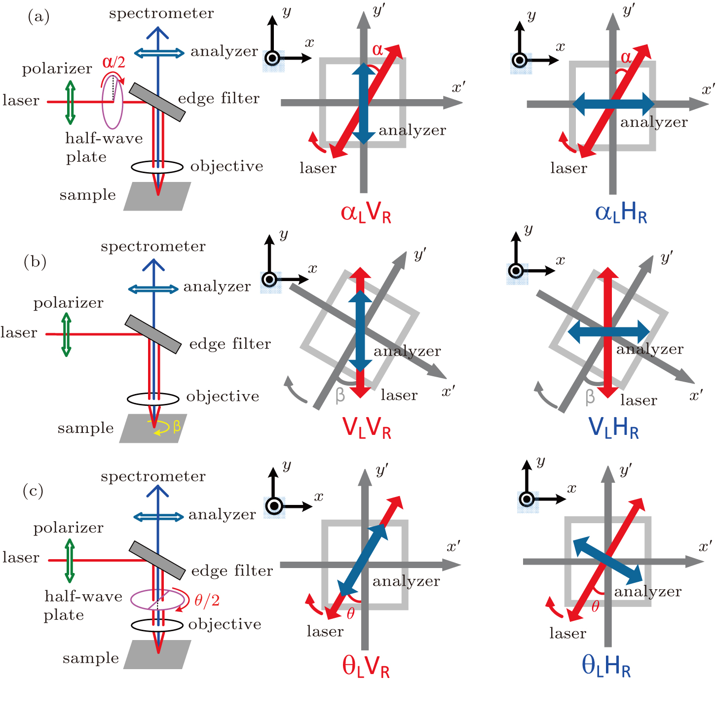
(color online) Schematic diagrams of three typical polarization configurations for angle-resolved polarized Raman spectroscopy: (a) and , (b) and , and (c) and , in which the polarizer is set in the beam path to make the incident laser to be vertically polarized. The analyzer before the spectrometer entrance selects vertically or horizontally polarized Raman signal to be detected. The half-wave plate is used to change the polarization direction of laser or signal. Laboratory coordinate(xyz) is represented by black arrows while crystal coordinate () is represented by gray arrows. Red two-way arrows stand for the incident laser polarization reaching at sample. The blue two-way arrows represent the original polarization of Raman signal corresponding to vertically or horizontally polarized signal selected by the analyzer before spectrometer entrance.