† Corresponding author. E-mail:
This paper reports a novel analytic model of this multichannel spark discharge, considering the delay time in the breakdown process, the electric transforming of the discharge channel from a capacitor to a resistor induced by the air breakdown, and the varying plasma resistance in the discharge process. The good agreement between the experimental and the simulated results validated the accuracy of this model. Based on this model, the influence of the circuit parameters on the maximum discharge channel number (MDCN) is investigated. Both the input voltage amplitude and the breakdown voltage threshold of each discharge channel play a critical role. With the increase of the input voltage and the decrease of the breakdown voltage, the MCDN increases almost linearly. With the increase of the discharge capacitance, the MDCN first rises and then remains almost constant. With the increase of the circuit inductance, the MDCN increases slowly but decreases quickly when the inductance increases over a certain value. There is an optimal value of the capacitor connected to the discharge channel corresponding to the MDCN. Finally, based on these results, to shorten the discharge time, a modified multichannel discharge circuit is developed and validated by the experiment. With only 6-kV input voltage, 31-channels discharge is achieved. The breakdown voltage of each electrode gap is larger than 3 kV. The modified discharge circuit is certain to be widely used in the PSJA flow control field.
As a promising active flow control method, the plasma flow control is an emerging research hotspot. The wide and promising prospect of this technology has been validated in many flow control fields, such as the separation control, jet boundary-layer transition control, high-speed jet control, noise mitigation.[1–6] Like the traditional surface dielectric barrier discharge actuators (SDBD), the plasma synthetic jet actuator (PSJA) has the advantage of the lack of moving parts. Moreover, the PSJA can produce a high-speed pulsed jet. The characteristic drives the PSJA to be applied in the high-speed flow control field successfully, such as shock-wave/boundary-layer interaction control,[7,8] shock-wave manipulation, and so on.[9,10]
The low efficiency of the PSJA has been validated by many experiment and simulation results.[11–14] Increasing the distance of the discharge region can improve the efficiency. But the distance is restricted by the input voltage. What is more, the PSJA actuator is different from the SDBD actuator,[15] which can be used to meter scale. The orifice of the PSJA is only in the order of millimeters,[16,17] which is far less than the region of the flow field needed to be affected. To solve these two problems, the PSJA array is necessary in the practical application. Based on a pulsed DC discharge circuit, the team of Clemens used a PSJA array to control the shock/boundary-layer interaction.[7,10] The PSJA array consisted of only 3 PSJAs, which was far from the number needed in the practical application. Owing to the large current-limiting resistor in the discharge circuit, most of the energy is wasted by the circuit resistor. Therefore, this circuit is not efficient to drive the PSJA array. However, different from the barrier discharge,[18,19] the resistance characteristic of the arc discharge channel is negative. As a result, it is difficult to drive the PSJA in serials by a power supply. As a result, several power supplies are needed to drive the actuator array, which is apparently not feasible in practice. Tie et al. proposed a six channel spark discharge method.[20] However, the necessary condition of very high trigger voltage (40 kV) and short rise time (25 ns) increases the technical requirements for the power supply.
To solve this problem, a special multichannel discharge circuit is developed by us, which can drive the multichannel discharge using only one supply circuit.[21] No extra resistor is necessary in this circuit. However, the electric characteristics of this circuit are not clear currently. The relationship between the circuit parameters and the maximum discharge channel number (MDCN) has not been uncovered. How to choose the circuit parameters lacks guiding theory.
In this paper, an electric model on this multichannel discharge circuit is put forward, which is validated by experimental data. Using this model, the influence of the circuit parameters on the MDCN is investigated. Based on the influence rules, an optimization of the multichannel discharge circuit is obtained and validated by the experiment.
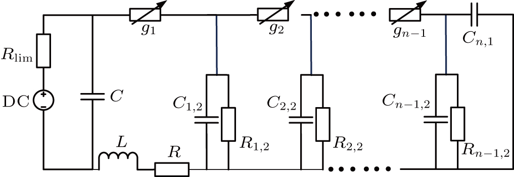
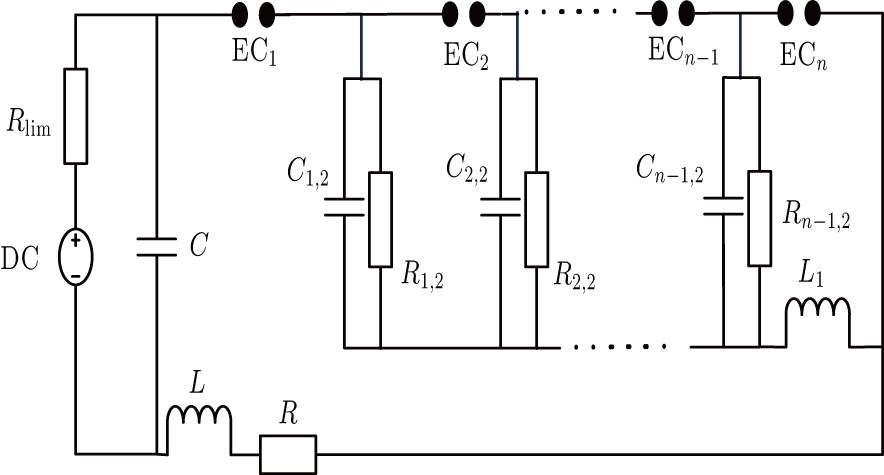
To achieve the multichannel discharge, a principle circuit is designed, which is shown in Fig. 


To establish this simulation model, some assumptions must be made. The electrode couple is seen as a capacitor before breakdown and a variable resistor after breakdown. The variable resistance is calculated based on an improved Mayr-type arc model developed by Pieter H. Schavemaker.[22] The breakdown voltage amplitude of the electrode couple is not fixed. The distribution satisfies the normal assumption. The breakdown delay time is not fixed. The distribution satisfies the normal assumption. The mean breakdown delay time is calculated using an empirical formula.[23] When the breakdown of electrode couple EC

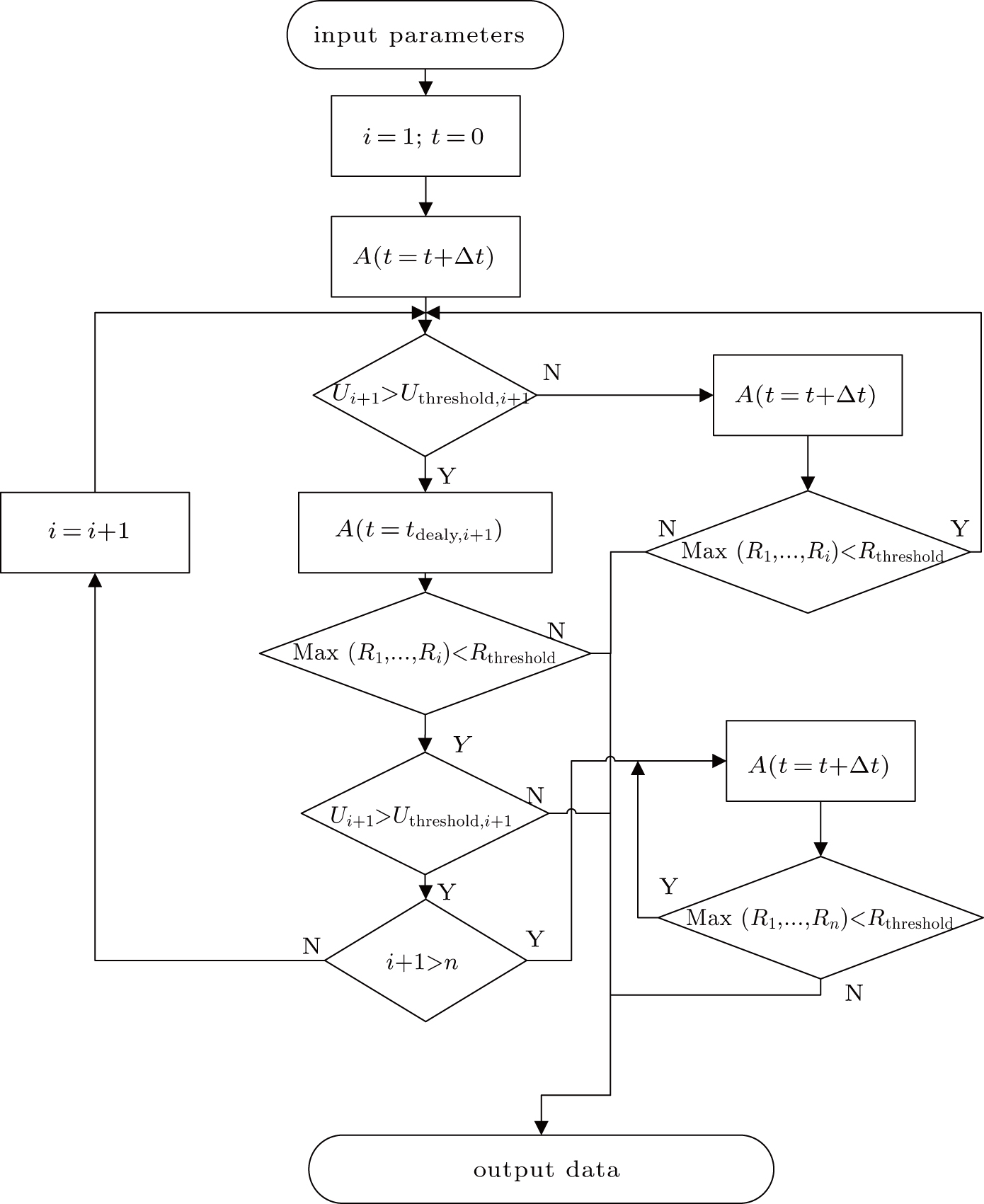
To simulate the multichannel discharge process, there are three main submodels. The first submodel is used to decide whether or not the breakdown of one electrode couple happens. When the breakdown happens, the electrode couple transforms from a capacitor to a variable resistor. The second submodel is used to calculate the voltage–current characteristic of the variable resistor. The last submodel is used to decide whether or not the spark channel between the electrode couple terminates.
The breakdown process is a complex process. The breakdown of one electrode couple is a random process. Even in the same condition, it is not definite whether or not the breakdown of one electrode couple happens. In this submodel, the criteria are defined as follows:
The voltage amplitude across the electrode couple must increase to a threshold value. The distribution of the threshold values in different times meets the normal assumption. The mean value is calculated by Eq. (
 |
The above condition must remain for a certain time, which is called the breakdown delay time. The distribution of the breakdown delay time values in different times meets the normal assumption. The mean value is calculated by an empirical formula, as Eq. (

The voltage–current characteristic of the variable resistor is calculated based on an improved Mayr-type arc model developed by Schavemaker. The arc model is described by the following equation. g is the arc conductance; U is the arc voltage; I is the arc current; 


 |
After breakdown, the arc conductance changes with the arc current and arc voltage. In this simulation model, when the arc conductance decreases to a threshold value, the discharge channel between the electrode couple is supposed to disappear.
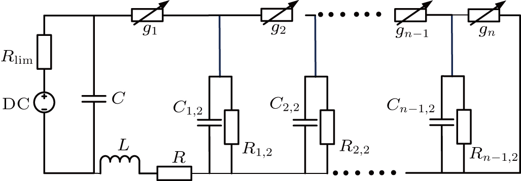
Based on the above assumptions, after the breakdown of the electrode couple EC

The differential equations of the above circuit are shown in Eq. (


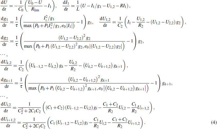 |
When the breakdown of the electrode couple EC
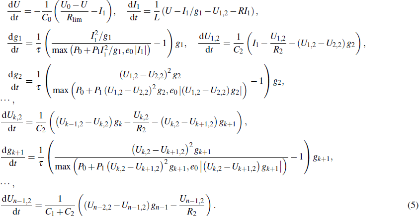 |
When the breakdown of the electrode couple EC
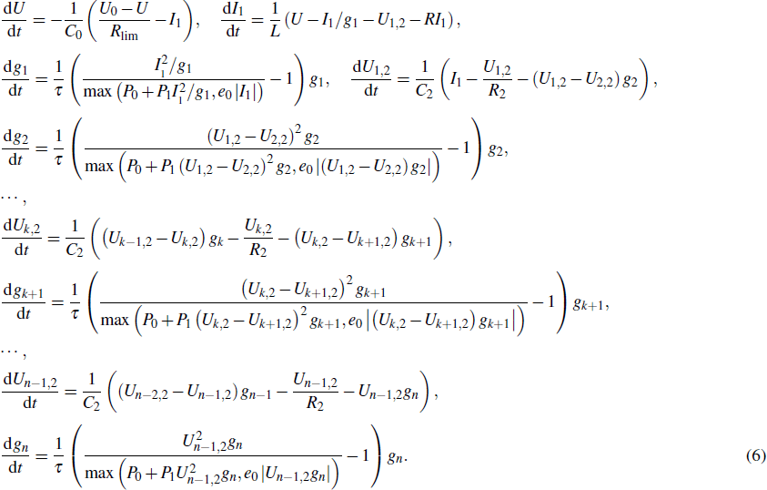 |
Based on the above submodels and differential equations, the multichannel discharge process can be simulated. The simulation flow chart is shown in Fig.
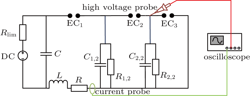
To validate the simulation model, an experiment system is built, as shown in Fig.
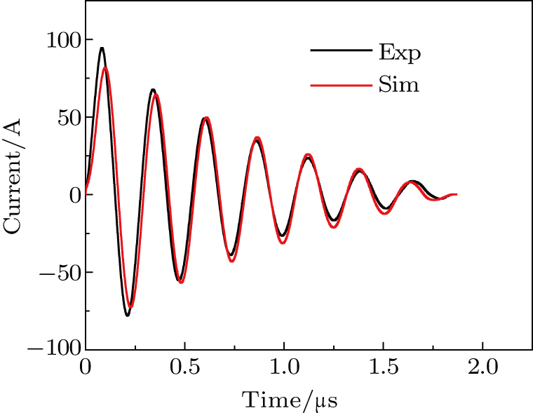
To improve the accuracy of the experimental data, the discharge electrodes are made of two stainless steel spheres. The diameter of the sphere is up to 25 mm, larger than the electrode couple distance. The two steel spheres are fixed on two micro positioning systems (sensitivity 1 μm), respectively. The voltage and the current are measured by a high-voltage probe (Tektronix, P6015) and a current probe (Pearson, 6600), respectively. An oscilloscope (Tektronix, DPO4014) is used to display and record the data. In this experiment, the capacitor C is 1 nF, the inductance is 1.63 μH, the total value of wire resistance and equivalent series capacitor resistance is 1.89 Ω. The values of capacitance and resistance are obtained by an impedance analyzer (Agilent 4285A).
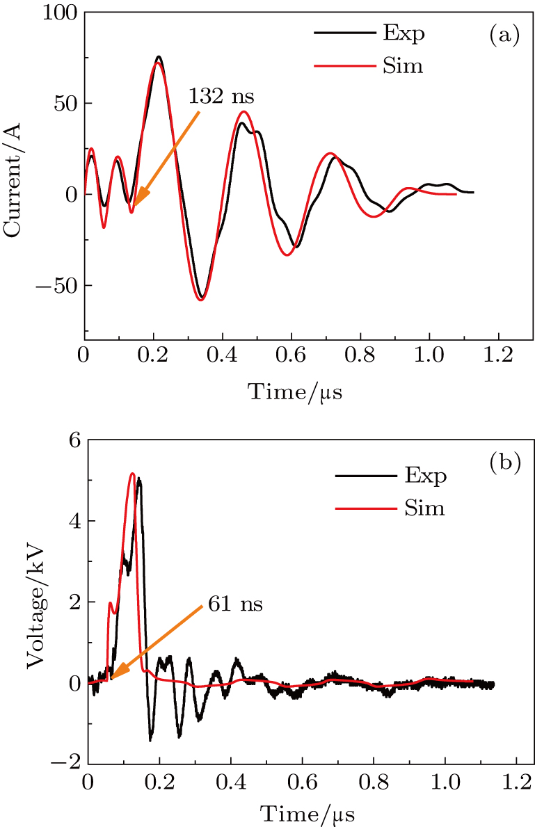
When the distance of EC


Based on these parameters, a three-channel discharge circuit is simulated. The measured and simulated results are shown in Fig. 


This novel multichannel discharge circuit can multiply the discharge channel. Based on this method, the region affected by the plasma actuators can be enlarged. To further understand this circuit, the characteristics of this circuit must be investigated.
Owing to the negative current–voltage (I–V) characteristic of the spark discharge, as previously reported,[24] the array of discharge can be only generated by using a distributed resistive ballast previously, where each spark discharge is individual ballast. However, in this special circuit, an array of discharge is generated without resistance ballast. Based on this model, the working mechanism of this circuit can be revealed in detail.
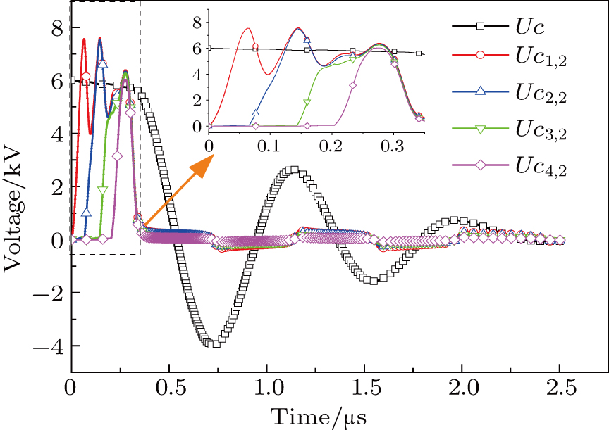
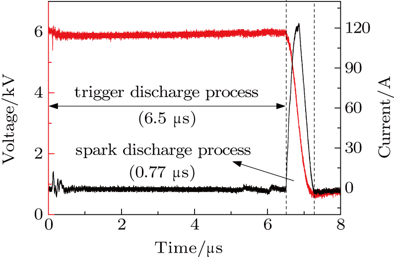
In a 5-channels discharge circuit, the voltage across C, 


It is known that, to ingite the air between the electrode couple, the high voltage is necessary. Before the breakdown of each electrode couple, the electrode couple, which can be seen as a small capacity capacitor, is connected with a large relay capacitor in serial. Therefore, when the power supply outputs the pulsed voltage, the impedance of relay capacitor can be ignored. The voltage across the electrode couple would increase until the breakdown. As the negative current–voltage (I–V) characteristic of the spark discharge, the voltage drop of an ignited electrode couple is so small that the discharge channel can be seen as wire. As a result, the voltage across the next electrode couple would increase until the breakdown. Taking advantage of the negative current–voltage (I–V) characteristic of the spark discharge and the impedance change induced by the breakdown, this circuit can generate multichannel discharge without distributed resistive ballast.
To ensure this circuit works properly, two aspects must be paid attention to. One is that the breakdown voltage of the electrode couple EC


The main parameters of this circuit which affect the maximum discharge channel number are shown in Table
| Table 1.
The main parameters of the multichannel discharge circuit. . |

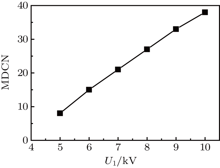
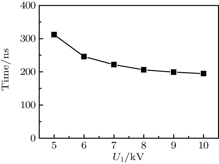
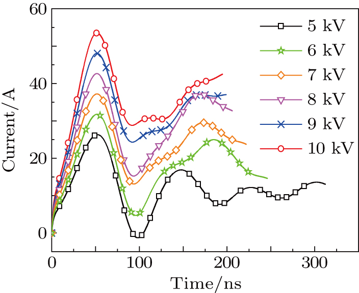
Except the 


This phenomenon is easy to explain. Equation (


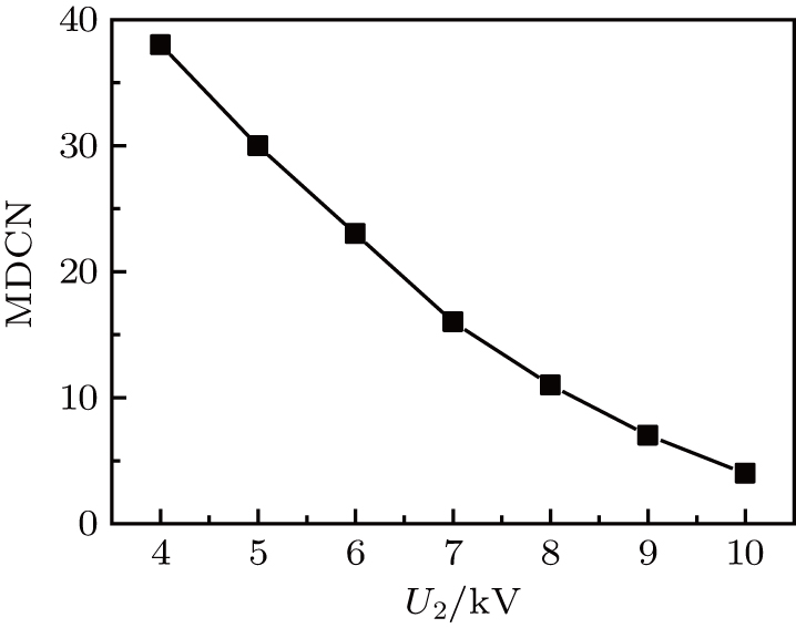
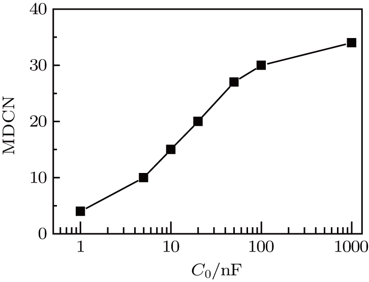
Except the 


In general, the increase of 


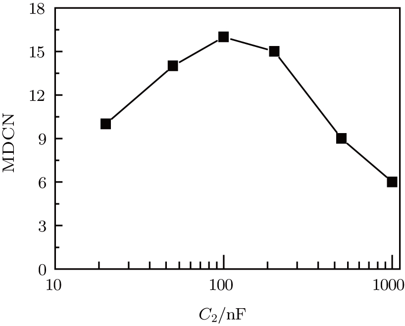
Except the 


Except the 


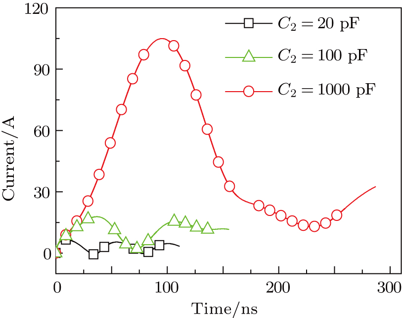
The reason for this phenomenon is as follows. With the decrease of the capacitance 


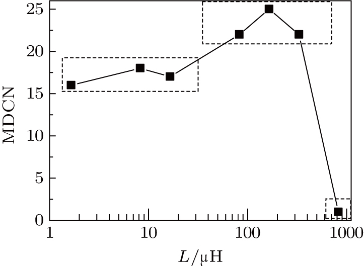
Except the L, the value of other parameters is set as follows: 


There are three stages in this curve. In the first stage, the inductance is less than 16.5 μH, and the maximum discharge channel number ranges from 16 to 18. When the inductance increases to a large value, the maximum discharge channel number increase to a higher stage, ranging from 22 to 25. But when the inductance increases too much, the discharge channel number decreases to only one.
Based on the self-made mathematical model, the influence of the multichannel discharge circuit parameters is investigated. These parameters can be decided into two categories. One can be not randomly changed to increase the discharge channel number. The voltage 


In this circuit, the inductance 

To validate this optimized circuit diagram, based on these optimized parameters, a 31-channel discharge experiment is designed. The discharge image is shown in Fig.
To deepen the understanding of the electrical characteristics and optimize the multichannel discharge circuit, an electric model on a multichannel discharge circuit is developed in this paper. The good agreement between the experiment and the simulation based on this model has shown the accuracy.
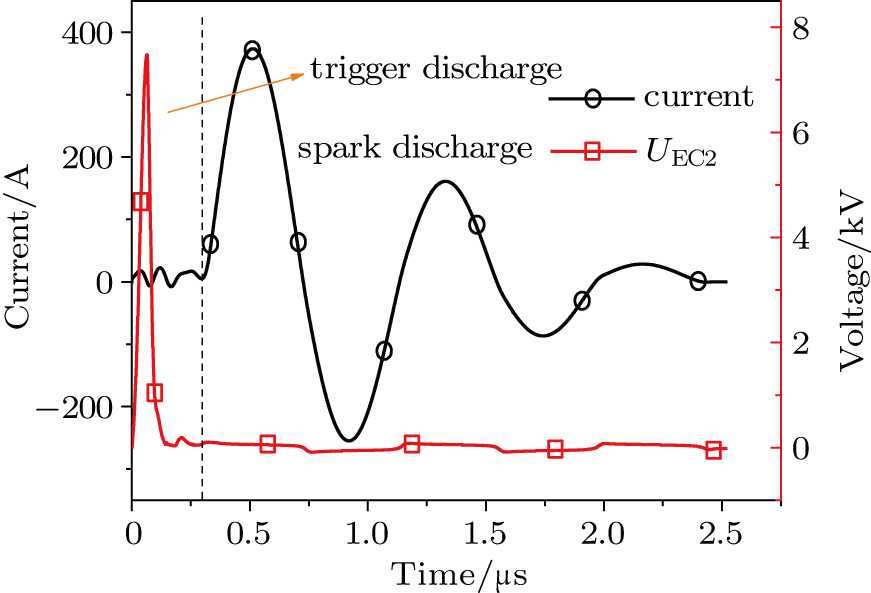
Results shown there are two stages in the working process of this multichannel discharge circuit. The first stage is the trigger discharge process. By voltage relay, the voltage across the electrode couples increases to its corresponding breakdown voltage in sequence. The second stage is the spark discharge process. When breakdown happens in all electrode gaps, the discharge current increases quickly.
Based on this model, the influence of the circuit parameters on the MDCN is investigated in detail. Both the input voltage amplitude and the breakdown voltage threshold of each discharge channel play a critical role. With the increase of the input voltage and the decrease of the breakdown voltage, the MCDN increases almost linearly. With the increase of the discharge capacitance, the MDCN first rises and then remains almost constant. With the increase of the circuit inductance, the MDCN increases slowly but decreases quickly when the inductance increases over a certain value. There is an optimal value of the capacitor connected to the discharge channel corresponding to the MDCN.
Based on these influence rules, to shorten the discharge time, a modified multichannel discharge circuit is developed and validated by the experiment. With only 6-kV input voltage, 31-channel discharge is achieved. The breakdown voltage of each electrode gap is larger than 3 kV. Owing to the increase of the plasma resistance, the capacitor deposits its energy in a short time, about 770 μs.
| [1] | |
| [2] | |
| [3] | |
| [4] | |
| [5] | |
| [6] | |
| [7] | |
| [8] | |
| [9] | |
| [10] | |
| [11] | |
| [12] | |
| [13] | |
| [14] | |
| [15] | |
| [16] | |
| [17] | |
| [18] | |
| [19] | |
| [20] | |
| [21] | |
| [22] | |
| [23] | |
| [24] |


