1. IntroductionSynchronization of chaotic systems gained acceleration after the master–slave concept was introduced by Pecora and Carroll.[1] Since then, numerous chaotic systems and electronic circuits have been studied for their synchronization dynamics.[2–8] Many natural systems have also been identified to exhibit chaos synchronization in their dynamics.[9–11] Several synchronization phenomena such as generalized, complete, phase, and lag synchronizations were identified in identical and non-identical chaotic systems and were studied both experimentally and numerically. A detailed numerical study on the different types of synchronization phenomena was presented by Boccaletti et al.[12]
Chaos synchronization has been studied in a variety of nonlinear electronic circuits because of their potential applications in secure transmission of signals.[13,14] With the observation of a chaotic attractor in the Chua circuit,[15] the existence of chaotic attractors in circuits was revealed. The implementation of Chua’s diode using operational amplifiers[16] enabled researchers to use the nonlinear element in a handful of chaotic electronic circuits.[8,17–19] Further, nonlinear elements with different v–i characteristics have been implemented using operational amplifiers.[20–22] Nonlinear circuits differ from each other mainly through the constitution of the nonlinear element that is present in the circuit. Hence, the chaotic dynamics is decided by the type of the nonlinear element. The dynamics of those circuits have been mostly analyzed through numerical experiments. The observation of chaos in a second-order non-autonomous circuit, namely, the Murali–Lakshmanan–Chua (MLC) circuit by Murali et al., paved the way to understanding the complexity underlying chaotic attractors. This lower dimensional system claims greater importance as it possesses a rich variey of chaotic dynamics resembling its higher dimensional counterparts. A few second-order non-autonomous chaotic systems with different circuit parameters and nonlinear elements exhibiting chaos were studied. Owing to the mathematical simplicity of second-order, piecewise linear chaotic systems, analytical solutions to their normalized state equations have been obtained for a good number of chaotic systems.[19,21,23–28] However, explicit analytical solutions explaining the synchronization dynamics of coupled systems are rare in the literature. Explicit analytical solutions explaining the complete synchronization phenomenon in coupled second-order non-autonomous circuits were studied recently.[29–31]
We present in this paper a generalized analytical solution to the state equations of coupled parallel LCR circuits with nonlinear elements. The nonlinear element is considered to be three-segmented piecewise-linear. An explicit analytical solution to the normalized state equations of the coupled system is presented. Further, the analytical solutions are used to study the synchronization dynamics of two different chaotic systems through two-parameter bifurcation diagrams. The stability of synchronization of the coupled identical chaotic systems is studied using the master stability function (MSF).[32–34] The analytical results thus obtained have been confirmed by experimental results.
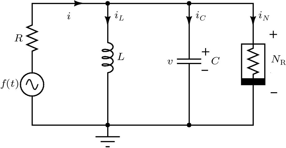
2. Circuit equationsA sinusoidally forced parallel LCR circuit with a nonlinear element
 connected parallel to the capacitor exhibiting chaotic dynamics is shown in Fig. 1. The nonlinear element
 determines the chaotic dynamics of the circuit for a proper choice of the other circuit parameters. The nonlinear elements considered for the present study are voltage-controlled and piecewise-linear.
The dynamical equations of the circuit in terms of the voltage v across the capacitor and the current iL flowing through the inductor obtained by Kirchoff’s laws are given as
where
g(
v) is the mathematical form of the voltage-controlled, piecewise-linear resistor given by
The terms
F and

represent the amplitude and frequency of the external sinusoidal voltage source, respectively. By using the rescaling parameters

,

,

,

,

,

,

, and
G = 1/
R, the normalized state equations of the circuit can be written as
The function
g(
x) can be written in the piecewise linear form as
The circuit parameters are chosen to obtain a chaotic behavior in the dynamics. The circuit parameters take different values when different nonlinear elements are used. The circuit explained above acting as the drive system can be unidirectionally coupled to another circuit with the same nonlinear element acting as the response system. The drive and the response systems operating with different sets of initial conditions are coupled together by a linear resistor and a buffer. The buffer acts as a signal driving element which isolates the drive system variables being affected by the response system. The normalized state equations of the response system can be written as
and the piecewise linear function

is
where

,

, and

is the coupling parameter. The state variables of the response system have been represented by

and

. The amplitude and frequency of the external forcing term of the drive and response systems are represented as

and

, respectively.
3. Explicit analytical solutionsFirst we summarize the explicit analytical solutions obtained for the normalized state equations of the system given in eq. (3). The analytical solutions are obtained for each of the piecewise-linear regions of the nonlinear element. In both nonlinear elements, the central region is taken as D0 and the outer regions in the positive and negative voltage regimes are taken as D+1 and D−1, respectively. In the central region, we have g(x) = ax with (0,0) as the fixed point. The roots
 may be either two real values or a pair of complex conjugates. When the roots are a pair of complex conjugates, the state variables y(t) and x(t) are
where

and

. When the roots are two real values, the state variables are
In outer regions
 , we have
 with
with
 ,
,
 as the fixed point. When the roots
 are a pair of complex conjugates, the state variables y(t) and x(t) in this region are given as
When the roots are two real values, the state variables are
where

and

,

correspond to

and
D−1 regions, respectively.
From the state equations of the response system, we observe that the dynamics of the response is influenced by the drive through the coupling parameter. Since the circuit equations are piecewise linear, each picewise linear region of the two systems could be coupled together to get a new set of equations which could be solved for each region. The new set of equations obtained from Eqs. (3) and (5) is
where

=

,

=

, and

take the values

or

depending upon the region of operation of the drive and response systems. From the new set of state variables

, the state variables of the response system

could be written as
One can easily establish that a unique equilibrium point
 exists for Eq. (11) in each of the following three subsets:
The stability of the fixed points given in Eq. (
13) can be calculated from the stability matrices. In the first case,
g(
x) and

take the values

and

, respectively, corresponding to the central region in the
v–
i characteristics of the nonlinear element, which has been taken as the

region of the difference system. In the

region, the stability determining eigenvalues are calculated from the stability matrix
In the second case, g(x) and
 take the values
 and
and
 , respectively. In these regions, the stability determining eigenvalues are calculated from the stability matrix
The eigenvalues of the difference system in all the three regions are determined by the strength of the coupling parameter.
When the coupling parameter
 , the coupled systems become independent of each other. Hence the drive and the response systems given by Eqs. (3) and (5) have the same solution for their state variables in all the three piecewise linear regions.
Now we present the explicit analytical solutions for the dynamics of the response system for coupling strengths
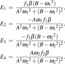
 . An explicit analytical solution to the dynamics of the response system could be obtained by finding a solution to the normalized state variables of the difference system given by eq. (11). The solutions of those equations are
 , for which the initial conditions are written as
 . From the solution
 and
and
 thus obtained, the state variables
 and
and
 can be found using Eq. (12) Since equation (11) is piecewise linear, the solution to each of the three regions can be obtained explicitly.
3.1. Region

In this region, g(x) and
 take the values ax and
 , respectively. Hence the normalized equations obtained from eq. (11) are
Differentiating Eq. (
16b) with respect to time and using Eqs. (
16a) and (
16b) in the resultant equation, we obtain
where

and

. The roots of Eq. (
17) are

. Since the roots
m1,2 depend on the coupling parameter, the orientation of the trajectories around the fixed point changes as the coupling parameter is varied.
3.1.1. Case aWhen
 , the roots m1 and m2 are a pair of complex conjugates given as
 , with
 and
and
 . By using the method of undetermined coefficients, the general solution to Eq. (17) can be written as
where
C1 and
C2 are integration constants and
Differentiating Eq. (
18) and using it in Eq. (
16b), we obtain
The constants
C1 and
C2 in the above equations can be evaluated by solving both Eqs. (
18) and (
19) for
C1 and
C2 at a suitable initial instant
t0, with

and

as the initial conditions at time
t =
t0, provided that the trajectory of the dynamical system just enters the region

at time
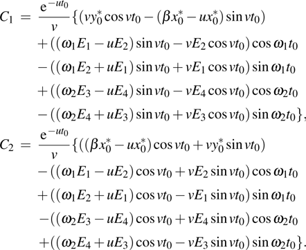
t0. The constants
C1 and
C2 thus obtained are
From the results of

obtained from Eqs. (
18) and (
19) and

obtained from Eqs. (
7a) and (
7b),

and

can be obtained from Eq.
(12).
3.1.2. Case bWhen
 , the roots m1 and m2 are real and distinct. The general solution to Eq. (17) can be written as
where
C1 and
C2 are the integration constants and the constants

are the same as those in case a. Differentiating Eq. (
20) and using it in Eq. (
16b), we obtain
The constants
C1 and
C2 are
From the results of

obtained from Eqs. (
20) and (
21) and

obtained from Eqs. (
8a) and (
8b),

and

can be obtained from Eq.
(12).
3.2. Region

In this region, g(x) and
 take the values
 and
and
 , respectively. Hence the normalized state equations obtained from Eq. (11) are
Differentiating Eq. (
22b) with respect to time and using Eqs. (
22a) and (
22b) in the resultant equation, we obtain
where

and

. The roots of Eq. (
23) are given by

.
3.2.1. Case aWhen
 , the roots m3 and m4 are a pair of complex conjugates given as
 , with
 and
and
 . By using the method of undetermined coefficients, the general solution to Eq. (23) can be written as
The constants

are the same as constants

in case a of the

region except that the constants
A and
B are replaced with
C and
D, respectively. Differentiating Eq. (
24) and using it in Eq. (
22b), we obtain
The constants
C3 and
C4 are the same as
C1 and
C2 in case a of the

region except that the constants

are replaced with the constants

, respectively. From the results of

obtained from Eqs. (
24) and (
25) and

obtained from Eqs. (
9a) and (
9b),

and

can be obtained from Eq.
(12).
3.2.2. Case bWhen
 , the roots m3 and m4 are real and distinct, the general solution to Eq. (23) can be written as
where
C3 and
C4 are the integration constants and the constants

are the same as those in case a. Differentiating Eq. (
26) and using it in Eq. (
22b), we obtain
The constants
C3 and
C4 are the same as
C1 and
C2 in case a of the

region. From the results of

obtained from Eqs. (
26) and (
27) and

obtained from Eqs. (
10a) and (
10b),

and

can be obtained from Eq.
(12).
Now let us briefly explain how the solution can be generated in the
 –
–
 phase space. The analytical solutions obtained above can be used to simulate the trajectories of the state variables
 and
and
 . With the time t being considered as the independent variable, the state variables evolve within each piecewise-linear region depending upon their initial values. If we start with the initial conditions
 in the
 region at time t = 0, the arbitrary constants C1 and C2 get fixed. Thus
 evolves as given by Eq. (19) up to either
 when
when
 or
or
 when
when
 . The next region of operation
 or
or
 thus depends upon the value of
 in the
 region at that instant of time. As the trajectory enters the next region of interest, the arbitrary constant corresponding to that region could be evaluated, with the initial conditions to that region being either (
 ) or (
 ). During each region of operation, the state variables of the response system evolve as
 and
and
 . The procedure can be continued for each successive crossing. In this way, the explicit solutions can be obtained in each of the regions
 and
and
 of the response system. The solution obtained in each region is matched across the boundaries and used to generate the dynamics of the response system.
4. Synchronization dynamics of the variant of MLC circuitIn this section, we discuss the synchronization dynamics observed in the coupled system when a Chua diode is used as the nonlinear element. The Chua diode is a piecewise-linear nonlinear element with three negative slope regions. It has been constructed using two operational amplifiers and six linear resistors as shown in Fig. 2(a). The v–i characteristic of the Chua’s diode with two negative outer slopes
 and one negative inner slope
 is shown in Fig. 2(b). A sinusoidally forced parallel LCR circuit with the Chua’s diode as the nonlinear element being called the variant of the MLC circuit was introduced by Thamilmaran et al.[18] The circuit exhibits chaotic dynamics for the chosen circuit parameters C = 10.15 nF, L = 445 mH, and
 . The negative slopes of the inner, outer regions and the breakpoints in the v–i characteristic curve of the piecewise-linear element shown in Fig. 1(b) are given as
 ,
,
 , and
, and
 . The rescaled circuit parameters take the values of
 . The frequency of the external periodic force has been fixed at
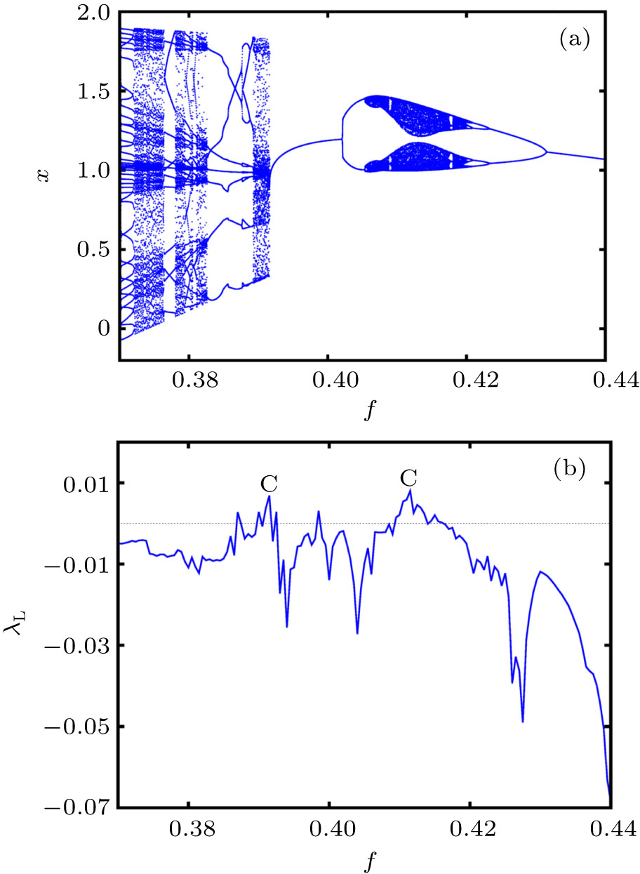
 and the amplitude f has been taken as the control parameter. The circuit exhibits a rich variety of bifurcations and chaos in its dynamics as the control parameter f is increased from zero. The rich variety of bifurcations and chaos exhibited by the variant of the MLC circuit has been studied experimentally and numerically.[18,19] The entire dynamics of the circuit is summarized through a one-parameter bifurcation diagram and the largest Lyapunov exponent as functions of the control paramter f in Fig. 3. The circuit exhibits chaotic attractors at two values of the control paramter f as indicated by the term C in Fig. 3(b). The chaotic attractors observed at f = 0.39 and f = 0.411 along with their corresponding power spectra indicating a broad band nature of frequencies is shown in Fig. 4.
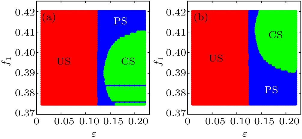
The analytical solutions obtained in Section 3 can be used to generate two-parameter bifurcation diagrams to identify the nature of synchronization observed in the coupled system. Figures 5(a) and 5(b) show the analytically obtained two-parameter bifurcation diagrams obtained in the
 –f1 plane for the response system operating at the chaotic states f2 = 0.39 and f2 = 0.411, respectively. The different synchronization regimes are color coded as follows: red-unsynchronized state (US), green-complete synchronization state (CS), and blue-phase synchronized state (PS). From Figs. 5(a) and 5(b), we can infer that the coupled systems remain unsynchronized for smaller coupling strengths and get completely synchronized for higher strengths. However, the complete synchronization of the chaotic attractors is observed only when the drive and the response systems are operated in identical chaotic states. Furthermore, in the non-identical chaotic states, the coupled systems undergo entrainment of their phases for larger values of the coupling strength.
A linear stability analysis of the eigenvalues m1 and m2 in the
 region reveals a transformation of the complex conjugate eigenvalues into real ones for
 . Similarly, the eigenvalues m3 and m4 in the
 region also get transformed from complex conjugates to real eigenvalues for
 . With the increase in the coupling parameter, the fixed points in the
 and
and
 regions transform into stable nodes, indicating the asymptotic convergence of the trajectories towards the origin, in their corresponding regions of phase space, within the synchronization manifold.
For studying complete synchronization, the amplitude and frequency of the drive and the response systems are fixed at
 ,
,
 while their initial condition has been fixed at
 and
and
 , respectively. Owing to the difference in their initial conditions, the chaotic attractors are unsynchronized for
 . Figure 6(a) shows the unsynchronized state of the coupled system for the coupling parameter
 , in the x–
 phase plane and the corresponding trajectory of the signals
 is shown in Fig. 6(c). The complete synchronization of the coupled systems in the x–
 phase plane for the coupling parameter
 is shown in Fig. 6(b) and the corresponding trajectory of the signals
 in Fig. 6(d). The Lyapunov exponents of the attractor shown in Fig. 6(a) are
 , and
, and
 . Hence, in the unsynchronized state, we have two positive Lyapunov exponents indicating the chaotic state of the drive and response systems. For the coupling strength
 , the Lyapunov exponents are
 , and
, and
 . The negative values of the conditional Lyapunov exponents
 confirm the synchronization of the coupled system.
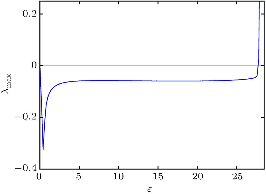
The stability of the synchronized state for the x-coupled systems given by Eqs. (3) and (5) is studied using the MSF approach. Figure 7 shows a plot of the MSF
 as a function of the coupling parameter
 for the
 coupling of the state variables. The x-coupled system enters a state of complete synchronization for
 , marked by the negative values of MSF. There exists a stable synchronized state in the region
 , within which the MSF is negative. For
 , the coupling between the systems becomes stronger and the synchronized state becomes unstable, leading to positive values of the MSF. Hence the x-coupled system enters into the synchronized state even for smaller values of the coupling strength and becomes unsynchronized for much higher values.
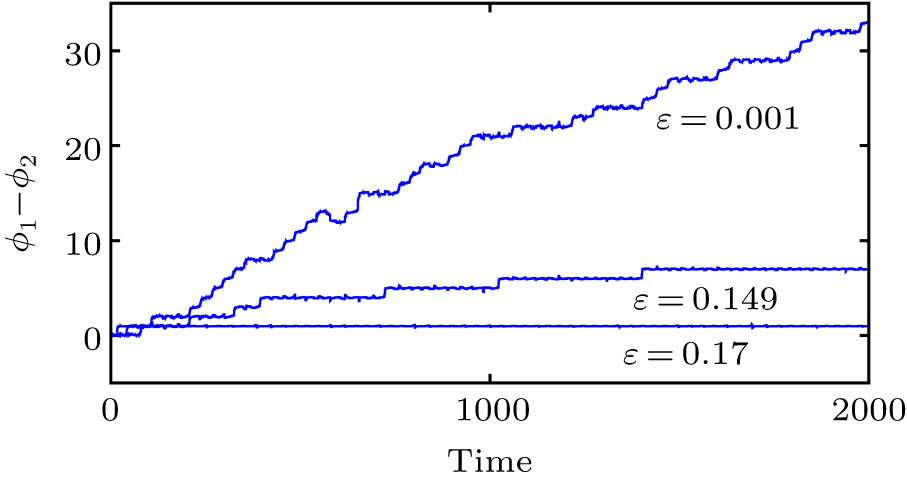
Now, we discuss the phenomenon of phase synchronization (PS) observed in the synchronization dynamics of the coupled system. From Figs. 5(a) and 5(b), we can observe that PS occurs only at the coupling of non-identical chaotic states. We consider the case of the response system being kept at the chaotic state f2=0.411. From the two-parameter bifurcation diagram shown in Fig. 5(b), we can observe that PS takes place when f1=0.39 for larger values of the coupling strength. Hence, the coupled system is studied for phase entrainment for different values of the coupling strength. Figure 8 showing the time series of the phase difference
 of the drive and the response systems indicates the unsynchronized, imperfectly, and perfectly phase synchronized states for the coupling strengths
 ,
,
 , and
, and
 , respectively. Hence, the non-identical chaotic systems are perfectly synchronized in their phases for the coupling strength
 .
.
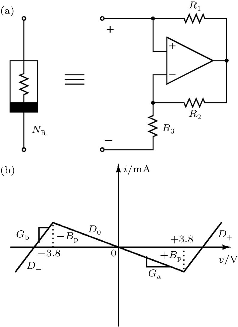
5. Synchronization dynamics of forced parallel LCR circuit with simplified nonlinear elementThe simplified nonlinear element, a kind of modified Chua’s diode, which was introduced by Arulgnanam et al.,[21] is shown in Fig. 9(a). It has been constructed with one operational amplifier and three linear resistors, hence making it the simplest nonlinear element ever constructed from a least number of circuit elements. The v–i characteristic of the simplified nonlinear element is also three segmented but with a negative inner slope
 and two positive outer slope regions
 as shown in Fig. 9(b). It is evident that the maximal Lyapunov exponents observed in the circuits with the simplified nonlinear element are relatively higher than those with the Chua diode as the nonlinear element.[21] The slopes of the inner, outer regions and the breakpoints in the v–i characteristic curve of the piecewise-linear element shown in Fig. 9(b) are given as
 ,
,
 , and
, and
 , respectively. The circuit parameters have been chosen as C = 13.13 nF, L = 163.6 mH, and R = 2.05 kΩ. The rescaled circuit parameters take the values β = 0.2592, a = −1.148, b = 5.125. The frequency of the external periodic force has been fixed at
 and the amplitude f has been taken as the control parameter. Figures 10(a) and 10(b) showing the one-paramter bifurcation diagram and the largest Lyapunov exponent of the circuit summarize the entire dynamics of the circuit. The circuit exhibits chaotic attractors at two values of the control parameter f = 0.695 and f = 0.855 indicated as C in Fig. 10(b). The two chaotic attractors along with their corresponding power spectra are shown in Fig. 11.
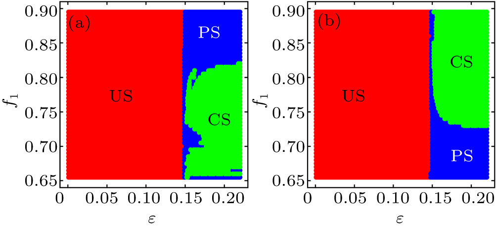
As the case of the variant of MLC circuit, this circuit is also studied for the synchronization of identical and non-identical chaotic attractors. The analytically obtained two parameter bifurcation diagrams in the
 –f1 plane for the response systems being fixed at the chaotic states f2=0.695 and f2=0.855, respectively, are shown in Figs. 12(a) and 12(b). Complete synchronization is observed when the drive and the response systems are kept at identical chaotic states while phase synchronization is observed when the two systems are kept at non-identical chaotic states. The linear stability analysis on the eigenvalues of the difference system shows bifuraction of the eigenvalues in the
 region as a function of the coupling parameter. The eigenvalues m1 and m2 in the
 region are found to be a pair of complex conjugates for
 , while they are real and distinct for
 . In the
 region, the eigenvalues m3 and m4 are found to be real, negative, and distinct for all values of the coupling strength.
For studying CS, the drive and the response systems are kept in identical chaotic states obtained at
 . However, they evolve from two different initial conditions given by
 and
and
 , respectively. Owing to the difference in their initial conditions, the chaotic attractors are initially unsynchronized as shown in Fig. 13(a) for
 . Hence the uncoupled system must have two positive Lyapunov exponents given by
 , and
, and
 , as expected. Figure 13(d) shows the time-series of the state variables x (blue line) and
 (magenta line) corresponding to the attractor shown in Fig. 11(a). As the coupling strength is increased in the range
 , an enhancement in the amplitude of the response signals is noticed. This is observed by an increase in the phase space of the attractor as shown in Fig. 13(b). Furthermore, an analysis on the Lyapunov exponents reveals the existence of two positive Lyapunov exponents for the coupled system and hence confirming the hyperchaotic behavior of the attractor. The Lyapunov exponents for the coupling strength
 are given by
 , and
, and
 . The time-series plot shown in Fig. 13(e) indicates the amplitude enhanced response signal
 (magenta line) with that of the drive signal x (blue line). With further increase in the coupling strength, the response system completely synchronizes with the drive system. Figure 13(c) shows the complete synchronized state of the coupled system in the x–
 phase plane for
 . The time-series of the state variables
 shown in Fig. 13(f) clearly indicates the complete synchronization of the coupled system.
Figure 14 shows the two largest Lyapunov exponents λ1 and λ2 of the coupled system. The positive values of λ1 and λ2 in the region
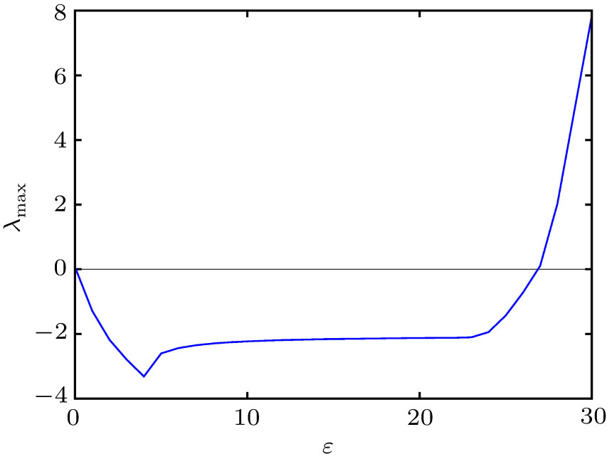
 confirm the hyperchaotic nature of the attractor shown in Fig. 13(b). The stability of the completely synchronized state is indicated by the negative values of the MSF
 in the region
 , as shown in Fig. 15. The phenomenon of complete synchronization has been evidenced in the coupled identical chaotic attractors through an emergence of hyperchaoticity in the dynamics.
For studying PS, the drive and the response systems are operated at non-identical chaotic states obtained at
 and
and
 , respectively. Similar to the case discussed with the variant of MLC circuit, the non-identical chaotic circuits synchronize in their phases as the coupling strength is increased. Figure 16 shows the difference in phases
 of the drive and the response systems for different values of the coupling strength. The phases of the two systems which are initially unsynchronized for
 undergo an imperfect synchronization of phases for
 and become perfectly synchronized for
 .
.
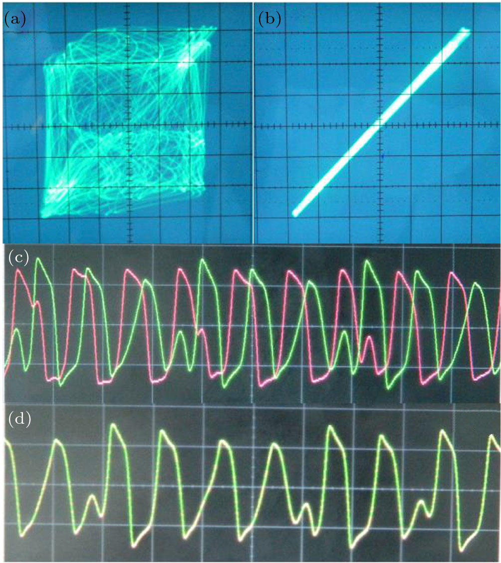
The experimental results confirming complete synchronization are shown in Fig. 17. The linear circuit element parameters are fixed as C = 10.36 nF, L = 168 mH, R = 2036 Ω, and
 . The voltage and the current signals of the drive and the response systems are represented as
 and
and
 ), respectively. The two systems are initially kept in the chaotic state observed at F = 7.8 V. For larger values of the coupling resistance RC, i.e., for
 , the coupling between the drive and the response systems becomes weak and hence they are unsynchronized. The unsynchronized state of the coupled system in the v–
 phase plane and the corresponding time-series of the signals v(t) (green line) and
 (red line) are shown in Figs. 17(a) and 17(c), respectively. As the coupling resistance is decreased, the coupling between the two systems becomes stronger enough to get completely synchronized. Figures 17(b) and 17(d) show the phase portraits and time-series plots of the completely synchronized state of the coupled system for the coupling resistance RC = 2 Ω.
6. ConclusionWe have presented in this paper a generalized explicit analytical solution for the coupled forced parallel LCR circuits with a three-segmented piecewise linear nonlinear element. Since the chaotic circuits studied here differ only by their nonlinear elements, the mathematical formulation of their normalized state equations remains the same. Hence, a generalized analytical solution is arrived at for the state equations and is used to study the synchronization dynamics of each system. The circuit with the Chua diode as the nonlinear element presents complete and phase synchronized states for coupling of identical and non-identical chaotic regimes. However, the circuits with the simplified nonlinear element exhibits complete synchronization through the evolution of a hyperchaotic attractor when coupled in the identical chaotic regime. Furthermore, the amplitude enhancement of the signals is observed in their dynamics along the path to phase synchronization. The entire dynamics of the two circuit systems has been observed through two-parameter bifurcation diagrams obtained from the explicit analytical solutions. The results obtained from the analytical solutions have been substantiated by solid numerical and experimental results. The analytical method presented in this study is simple as it involves only the coupling of similar regions of the drive and response and finding the solutions to each coupled region. This method has been checked earlier with yet another simple chaotic circuit, namely, the Murali–Lakshmanan–Chua circuit.[29] In this paper, we have confirmed the reliability of this analytical method and its solution to unidirectionally coupled picewise linear systems by presenting two-parameter bifurcation diagrams. Hence we suggest that this method could be applied for an effective study of synchronization and its mechanism in unidirectionally coupled, forced parallel LCR circuits, with any type of three-segmented piecewise linear nonlinear element.
Acknowledgement
One of the authors A Arulgnanam gratefully acknowledges Dr. K Thamilmaran, Center for Nonlinear Dynamics, Bharathidasan University, Tiruchirapalli, for his help and permission to carry out the experimental work during his doctoral programme.


