Performance improvement of continuous carbon nanotube fibers by acid treatment
Zhang Qiang1, 3, Li Kewei1, Fan Qingxia1, 3, Xia Xiaogang1, 3, Zhang Nan1, Xiao Zhuojian1, 3, Zhou Wenbin1, Yang Feng1, 3, Wang Yanchun1, 2, 3, Liu Huaping1, 2, 3, Zhou Weiya1, 2, 3, †
Beijing National Laboratory for Condensed Matter Physics, Institute of Physics, Chinese Academy of Sciences, Beijing 100190, China
Beijing Key Laboratory for Advanced Functional Materials and Structure Research, Beijing 100190, China
University of Chinese Academy of Sciences, Beijing 100049, China


† Corresponding author. E-mail: wyzhou@iphy.ac.cn

Project supported by the National Basic Research Program of China (Grant No. 2012CB932302), the National Natural Science Foundation of China (Grant Nos. 11634014, 51172271, 51372269, and 51472264), and the “Strategic Priority Research Program” of the Chinese Academy of Sciences (Grant No. XDA09040202).

Abstract

Continuous CNT fibers have been directly fabricated in a speed of 50 m/h–400 m/h, based on an improved chemical vapor deposition method. As-prepared fibers are further post-treated by acid. According to the SEM images and Raman spectra, the acid treatment results in the compaction and surface modification of the CNTs in fibers, which are beneficial for the electron and load transfer. Compared to the HNO3 treatment, HClSO3 or H2SO4 treatment is more effective for the improvement of the fibers’ properties. After HClSO3 treatment for 2 h, the fibers’ strength and electrical conductivity reach up to ∼ 2 GPa and ∼ 4.3 MS/m, which are promoted by ∼ 200% and almost one order of magnitude than those without acid treatment, respectively. The load-bearing status of the CNT fibers are analyzed based on the downshifts of the G band and the strain transfer factor of the fibers under tension. The results reveal that acid treatment could greatly enhance the load transfer and inter-bundle strength. With the HClSO3 treatment, the strain transfer factor is enhanced from ∼ 3.9% to ∼ 53.6%.

1. Introduction

Carbon nanotube (CNT), as a hollow nano-fiber, is particularly attractive because of its unique structure, low density, and remarkable mechanical, electrical, thermal and optical properties.[1] For practical applications, great effort has been made to assemble CNTs into macroscopic structures,[2] especially the continuous CNT fibers which is one of the most promising routes to exploit the outstanding axial properties of nanotubes.[35] CNT fibers are positioned for high-value applications, such as aerospace electronics, structural fibers, multi-functional fabrics, and composites.[68] Up till now, several methods have been established to fabricate CNT fibers, including wet-spinning fibers from a liquid suspension of CNTs, drawn from a vertically aligned CNT forest grown on a solid substrate or spun directly from the synthesis reaction zone in a chemical vapor deposition (CVD) system.[911] However, the performance of the CNT fibers is still far below that of individual CNTs.[1,4] Therefore, studies about the post-treatment of original CNT fibers for improvement of their mechanical and electrical properties are of great significance.[1217]

In this work, we report the effects of various acid treatments on the properties of continuous CNT fibers which have been prepared through shrinking CNT films synthesized by an improved CVD method. The comparison and analysis of the experimental results reveal that the fibers’ mechanical properties and electrical conductivity can be increased effectively by appropriate acid post-treatment.

2. Experiment section
2.1. Continuous preparation of CNT fibers

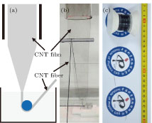
The continuous CNT fiber was directly prepared through in situ shrinking a CNT film with water and the corresponding procedure was illustrated in Fig. 1. The CNT films were synthesized by an improved CVD method. The feedstock for CNT synthesis and carrier gas were introduced into a furnace with the heating reaction region temperature of 1100 °C–1150 °C. The feedstock contained methane of 20 sccm–40 sccm as carbon source, ferrocene of 0.2 g/h–0.5 g/h as catalyst and sublimed sulfur of 5 mg/h–30 mg/h as promoter. The carrier gas was argon of 1.5 slm–2 slm. A CNT film was continuously out of the furnace with the carrier gas, and then was densified and shrunk into a continuous fiber by soaking in water (Figs. 1(a) and 1(b)). Finally, the continuous fiber was collected on a spinning polytetrafluoroethene (PTFE) winder (Fig. 1(c)). In order to reduce the measurement error, the continuous fibers were infiltrated with ethanol and then dried at 120 °C for 12 h in a vacuum oven before further characterizations.

Fig. 1. (color online) Continuous fabrication of a CNT fiber. (a) Schematic diagram of the equipment and synthetic process of a continuous CNT fiber. (b) A photograph of a continuous CNT fiber fabricated through in situ shrinking a CNT film with water. (c) A CNT fiber of ∼ 100 m in length collected on a PTFE winder.
2.2. Acid treatment

Dry CNT fibers were immersed in acid (HNO3 (∼ 67%), H2SO4 (∼ 70%), and HClSO3 (∼ 99%)) for several hours and then twisted until the fiber was not shrinking to remove the extra acids and compact the fiber. The twisting process was carried out using a hand-held spindle or an automatic spinning machine in a fume hood. Finally, the fiber was washed by deionized water and dried under some tension at 120 °C for 12 h in a vacuum oven. As control experiments, the fibers with ethanol infiltration were twisted and dried.

2.3. Characterization

The diameter, morphology, and microstructures of CNT fibers were characterized by scanning electron microscope (SEM, Hitachi 4800) and transmission electron microscope (TEM, Tecnai F20). Raman scattering spectra were recorded by LabRAM HR800 (HORIBA Jobin Yvon Inc.) with an excited wavelength of 633 nm. Resistances of fibers were measured by a Keithley-2400 sourcemeter with four-probe method under a current of 0.1 mA, using a sample with a gauge length of 50 mm. Mechanical property measurements were performed on a dynamic mechanical analyzer (DMA, Q800, TA Instruments) at a tensile speed of 0.05 mm/min, using a single CNT fiber pasted onto a hollow card with a gauge length of 15 mm. Raman spectra under continuous strain were obtained by combining the Raman spectra system and a homemade one-dimensional tensile platform. The one-dimensional tensile platform equipped with a micrometer can realize accurately continuous change of strain loaded along the long axis of the fibers.

3. Results and discussion
3.1. Morphology and performance of the continuous fibers

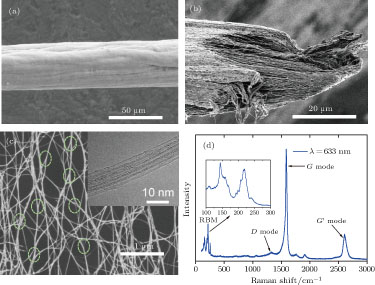
The performance, output and diameter of the continuous fiber can be controlled by adjustment of the synthesis conditions and collection speed. In general, the collection speed is 50 m/h–400 m/h and the fiber diameter is 10 μm–90 μm. Figure 2(a) shows an SEM image of the fiber with a diameter of ∼ 40 μm in collection speed of ∼ 150 m/h. The fiber consists of a continuous reticulate network of CNT bundles with diameter of 10 nm to 100 nm primarily (Fig. 2(c)), which are partially aligned along the collection direction due to the mechanical drag during the higher collection speed.[18] As shown in Fig. 2(c), the CNTs form into Y-type junctions, during the high-temperature synthesis process, resulting in very long and good inter-bundle connections between different CNTs.[2] This unique reticulate structure is very effective for electrical and load transport.[19]

Fig. 2. (color online) (a) and (b) SEM images of the surface and fracture morphology of a CNT fiber. (c) SEM image of a continuous reticulate network of CNT bundles with Y-type junctions indicated by dot circles. The inset shows an HRTEM image of CNTs with dominant single-walled structure. (d) Raman spectrum for the fiber with the excited laser wavelength of 633 nm. The inset shows RBM peaks located between 130 cm−1 and 270 cm−1.

The constituent of CNTs is mainly single-walled. The high resolution TEM (HRTEM) image, shown in inset of Fig. 2(c), demonstrates that a bundle consists of dominant single-walled nanotubes (SWCNTs) with very clean surface. Raman scattering spectra of the continuous fibers is shown in Fig. 2(d). The radial breathing mode (RBM) peaks (ω), ranging from 130 cm−1 to 270 cm−1, show that the diameters (dt) of the corresponding CNTs are mainly between 0.9 nm and 2 nm, assuming a relation ωRBM = 248/dt.[20] In addition, the extremely high ratio (> 20) of the intensity of the G peak to that of the D peak indicates that the CNTs have high purity and have been graphitized well. During tracking the CNT length under SEM and TEM, no clear results were obtained since CNT ends were seldom seen, presumably because of their very long lengths (> several hundreds μm).

The original fibers, directly fabricated at optimized synthesis conditions, were characterized and showed electrical conductivity of 0.3 MS/m–0.4 MS/m, strength of 0.5 GPa– 0.7 GPa and modulus of 10 GPa–20 GPa, respectively. Because of the high-purity, ultra-long CNTs and the unique hierarchical reticulate structure formed at high temperature, the performance of the continuous fibers remarkably precedes that of the most traditional materials such as Bucky paper, but is still far from that of an individual SWCNT.[3,14] The weak interaction between different CNTs and bundles is one of the most important reasons for this.[5] From a typical fracture morphology of a fiber, shown in Fig. 2(b), it can be seen that the inter-bundle contact structure is loose, which means the higher barrier for the charge carrier and load transfer between CNTs. Densification, achieved physically by liquid infiltration, twisting, rolling press, drawing through diamond dire dies, etc, can effectively decrease the barrier to enhance the fiber performance.[14,2123]

3.2. Effects of acid treatment

Because of the convenient operation and high efficiency, acidizing is widely used in treatment of CNTs through purification or introduction of functional groups.[2427] Here, the idea of the CNT fiber’s properties improved by acid treatment, results from two aspects. First, most acids have the wettability of CNTs and can effectively remove the impurity in the fibers,[4] which are also beneficial for the fiber densification. Second, acid treatment can introduce the functional groups, which can enhance the interaction of CNTs and the fiber’s electrical conductivity by doping.[28] Concentrated nitric acid, concentrated sulfuric acid, and chlorosulfonic acid are the most common acids for treatment of CNTs and mainly used in purifying, mixing, dissolving, modification, etc.[3,4]

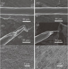
The effects of HNO3, H2SO4, and HClSO3 on the morphology and performance of the CNT fibers are shown in Figs. 3 and 4. HNO3, H2SO4, and HClSO3 can compact the fibers and the fiber’s diameter decreases by 8 %–12% after the acidization. As shown in Figs. 3(a) and 3(b) the diameter decreases from ∼ 28 μm to ∼ 25 μm with HClSO3 treatment. This compaction results from both purification and intertube spacing decrease. The CNTs on the fiber surface (Fig. 3(e)) are more compact after acid treatment (Fig. 3(f)).

Fig. 3. (color online) SEM images of morphologies of twisted CNT fibers without (panels a, c, and e) and with (panels b, d, and f) chlorosulfonic acid treatment. Panels (a) and (b) are the twisted CNT fibers. The diameter is reduced distinctly after the acid treatment. (c) and (d) The fracture morphology of the fibers in panels (a) and (b), respectively. The sliding distance is decreased significantly after acid treatment. (e) and (f) The surface of the fibers in panels (a) and (b), respectively. The CNTs in the fibers are dense after the acid treatment.
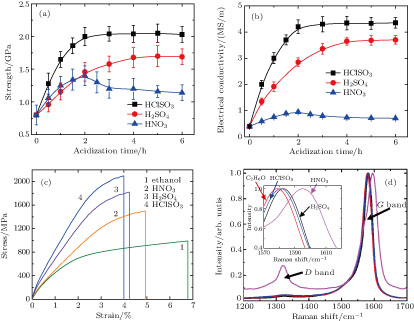
Fig. 4. (color online) Influences of acid treatment on the twisted fiber’s performance. (a) Tensile strength and (b) electrical conductivity at different acidizing time. (c) The typical stress–strain curves and (d) Raman spectra of the sample at different acidizing time (5 hours for H2SO4 and HCISO3, 2 hours for HNO3). Inset of panel (d) shows blue shifts of the G band after acid treatment. The D band intensity greatly increases after immersion of the fiber in HNO3 for 2 hours. All Raman spectra are normalized by the G band intensity.

Besides the morphology changes, the acid treatments also remarkably improve the mechanical and electrical properties of fibers. The results of the tensile strengths and electrical conductivity at different acidizing time are shown in Figs. 4(a)4(c). For a twisted fiber without acidizing, the tensile strength is ∼ 0.9 GPa, modulus is ∼ 30 GPa, and electrical conductivity is ∼ 0.45 MS/m, respectively. With the time extension of HNO3 treatment, the fibers’ properties are improved first and then declined. The best performance (strength ∼ 1.4 GPa, modulus ∼ 43 GPa, and electrical conductivity ∼ 0.85 MS/m, respectively) shows up for 2 h of HNO3 treatment. These results are similar to that reported by Meng[26] and Wang.[27] For the fibers with H2SO4 or HClSO3 treatment, their properties keep being improved in the first 4 h or 2 h, respectively, and then stabilize with the further treatment. After H2SO4 treatment for 4 h, the fiber’s strength is ∼ 1.7 GPa, modulus ∼ 60 GPa, and electrical conductivity ∼ 3.6 MS/m; while after HClSO3 for 2 h, the fiber’s strength is ∼ 2 GPa, modulus ∼ 78 GPa, and electrical conductivity ∼ 4.3 MS/m. The fibers’ properties treated by H2SO4 are approximate to that treated by HClSO3, while both of them precede that treated by HNO3. The typical stress–strain curves of the fibers are shown in Fig. 4(c) and are similar to that of plastic polymers. With the tension increases, the tensile behavior transforms from elastic response to plastic deformation.[17] This process will be further discussed below.

Except the aforementioned compaction, the performance improvement of the fiber with acidizing also results from the surface modification.[12,27] Although the diameter decrease is similar (by 8%–12%), the performance of the fiber with H2SO4 and HClSO3 treatment is superior to that with HNO3 treatment. This result implies that the surface modification by acidizing also benefits the improvement of fibers’ properties.[26] For example, the load transfer between CNTs would be promoted by enhancements of the intertube interaction and interfacial shear property, due to the existence of dipole–dipole interaction and possible hydrogen bonding.[12] In addition, the functional groups might improve the conductivity by serving as excellent dopant and efficient electron pathways. The HNO3 treatment effectively modifies CNT surfaces by introducing abundant functional groups, such as –COOH and –OH, which has been reported many times.[24,2628] For the fibers with H2SO4 treatment, the sulphate ion from the residual sulfuric acid in the fiber is also excellent dopant.[10] As for the HClSO3 treatment, it is similar to the H2SO4 treatment, due to the reaction between HClSO3 and the moisture generating H2SO4 and HCl.[4] The surface modification can be proved by the Raman spectra (Fig. 4(d)). Downshifts of G bands (inset in Fig. 4(d)) are observed for the fibers with acidizing, due to the transfer of the electrons from CNTs to the dopants.[28] With the time of HNO3 treatment increasing, the fibers’ properties get worse because the CNT crystalline structure could be destroyed with the introduction of more functional groups.[26,28] This structure destruction can be reflected by the D band intensity increase in Raman spectra (Fig. 4(d)).

It has been reported that the conduction of CNT fibers is mainly controlled by electron hopping mechanism.[29,30] As the intertube spacing became smaller, the hopping is enhanced and the contact resistance is reduced significantly.[22,24,31] In addition, the smaller intertube spacing also improves the interfacial shear property.[14,31,32] The sliding is dominant for the fracture of a fiber because of the weak intertube interaction.[17,26] After the acidizing, the sliding distance decreases significantly from tens of μm (Fig. 3(c)) to 5 μm–10 μm (Fig. 3(d)), which results from the more effective interfacial shear property.

3.3. In situ Raman spectra under strain and strain transfer factor

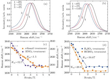
The in situ Raman measurements were employed to unveil the load-bearing status of the CNT fibers.[33] Figures 5(a) and 5(b) show the Raman spectra of the typical G bands of fibers with ethanol infiltration and HClSO3 treatment under strain. When Raman measurements are performed at different strains, there are two-stage features for the downshifts of the G band.[16] At a low strain, the downshift is near-linear for the fibers with a rate of ∼ 1.5 cm−1/1% strain with ethanol infiltration, ∼ 12.7 cm−1/1% strain with HNO3 treatment for 2 hours, ∼ 16.7 cm−1/1% strain with H2SO4 treatment for 5 hours and ∼ 20.6 cm−1/1% strain with HClSO3 treatment for 5 hours, respectively. Once the strain exceeds a certain point (∼ 4%, ∼ 2.2%, ∼ 1.8%, and ∼ 1.6% for 4 kinds of fibers, respectively), the peak position of G band would be at plateaus until the final breakage of the specimens. Figures 5(c) and 5(d) show the statistical information of the downshifts of G bands for various fibers under tension.

Fig. 5. (color online) Typical G bands of the twisted CNT fibers (a) without acid treatment and (b) with HClSO3 treatment for 5 hours. (c) and (d) the Raman shift of the G bands for various fibers as a function of applied strain, where Km is the slope of Raman shift to strain. Straight lines are plotted to guide the eyes.

According to the variation of the Raman spectra, the micromechanical process in macroscale CNT fibers is analyzed.[17,33] The macroscale strain from the axial extension of CNTs can be estimated, based on the downshift rate of the G band (Km) at a low-strain stage. The downshifts of the G band are expected, which arise from the weakening of the carbon–carbon bonds when the inter-atomic distance elongated.[16] In the light of Corning’s work, the average Km is 37.5 cm−1/1% strain for strained individual SWNTs.[34] This value is much higher than that of the CNT fibers without or with acid treatment, which implies the macroscale strain of the fibers results from not only the axial extension of the CNT bundles but also the CNT network deformation at a low-strain stage. Furthermore, the macroscale strain from CNTs’ axial extension are quantitatively evaluated, based on the strain transfer factor (STF) which is defined as the ratio of Km for a CNT fiber to that for an individual CNT (37.5 cm−1/1% strain).[16] The STF is only ∼ 3.9% for the CNT fibers with ethanol infiltration, which implies that CNTs’ axial extension merely contributes several percent to the total macroscale strain. After acid treatment, the STF is improved by at least one order of magnitude (the fiber’s STF ∼ 33% with HNO3 treatment, ∼ 43% with H2SO4 treatment and ∼ 53.6% with HClSO3 treatment, respectively), which means the strain transfer in the fiber is more effective.[33] In addition, in Figs. 5(c) and 5(d), the turning point of the G band downshifts could indicate the general strength of the interbundle junctions.[17] For the fiber with ethanol infiltration, the downshift of the G band reaches to ∼ 6 cm−1 at a strain of ∼ 4% and then to a plateau even though more strain is applied. Meanwhile, by acid treatment, the turning point of downshift can increase to 28 cm−1 (with HNO3), 30 cm−1 (with H2SO4), and 33 cm−1 (with HClSO3), respectively, which indicate the interbundle strength is greatly improved (Figs. 4(a) and 4(c)).

4. Conclusion

In summary, a CNT fiber, directly and continuously prepared at a collection speed of 50 m/h–400 m/h via an improved CVD method, consists of a continuous reticulate network with lots of Y-type junctions and shows electrical conductivity of 0.3 MS/m–0.4 MS/m, strength of 0.5 GPa–0.7 GPa and modulus of 10 GPa–20 GPa. Its performance markedly precedes that of the most traditional materials such as Bucky paper, but is still far worse than that of an individual SWCNT.[3,14] We treat the as-grown CNT fibers by acidizing to densify and modify the fibers and effectively reduce the barrier for the charge carrier and load transfer between CNTs. Compared to the HNO3 treatment, HClSO3 or H2SO4 treatment is more effective for the improvement of the fibers’ properties. After HClSO3 treatment, the fibers’ strength and electrical conductivity are promoted by ∼ 200% and almost one order of magnitude than those without acid treatment, respectively. The results of the G band downshifts and strain transfer factor of the fibers under tension reveal that acid treatment could greatly enhance the load transfer and inter-bundle strength. The modified CNT fibers have great potential applications in high-strength and conductivity composites, multifunctional fabrics and structural fibers.

Reference
[1] De Volder M F L Tawfick S H Baughman R H Hart A J 2013 Science 339 535
[2] Ma W J Song L Yang R Zhang T H Zhao Y C Sun L F Ren Y Liu D F Liu L F Shen J Zhang Z X Xiang Y J Zhou W Y Xie S S 2007 Nano Lett. 7 2307
[3] Behabtu N Green M J Pasquali M 2008 Nano Today 3 24
[4] Behabtu N Young C C Tsentalovich D E Kleinerman O Wang X Ma A W K Bengio E A ter Waarbeek R F de Jong J J Hoogerwerf R E Fairchild S B Ferguson J B Maruyama B Kono J Talmon Y Cohen Y Otto M J Pasquali M 2013 Science 339 182
[5] Chae H G Kumar S 2008 Science 319 908
[6] Cleuziou J P Wernsdorfer W Bouchiat V Ondarcuhu T Monthioux M 2006 Nature Nanotech. 1 53
[7] Cheng Q Bao J Park J Liang Z Zhang C Wang B 2009 Adv. Funct. Mater. 19 3219
[8] Lima M D Li N de Andrade M J Fang S Oh J Spinks G M Kozlov M E Haines C S Suh D Foroughi J Kim S J Chen Y Ware T Shin M K Machado L D Fonseca A F Madden J D W Voit W E Galvao D S Baughman R H 2012 Science 338 928
[9] Jiang K L Li Q Q Fan S S 2002 Nature 419 801
[10] Ericson L M Fan H Peng H Q Davis V A Zhou W Sulpizio J Wang Y H Booker R Vavro J Guthy C Parra-Vasquez A N G Kim M J Ramesh S Saini R K Kittrell C Lavin G Schmidt H Adams W W Billups W E Pasquali M Hwang W F Hauge R H Fischer J E Smalley R E 2004 Science 305 1447
[11] Li Y L Kinloch I A Windle A H 2004 Science 304 276
[12] Roenbeck M R Furmanchuk A o An Z Paci J T Wei X Nguyen S T Schatz G C Espinosa H D 2015 Nano Lett. 15 4504
[13] Liu Q Li M Gu Y Zhang Y Wang S Li Q Zhang Z 2014 Nanoscale 6 4338
[14] Beese A M Wei X Sarkar S Ramachandramoorthy R Roenbeck M R Moravsky A Ford M Yavari F Keane D T Loutfy R O Nguyen S T Espinosa H D 2014 ACS Nano 8 11454
[15] Naraghi M Filleter T Moravsky A Locascio M Loutfy R O Espinosa H D 2010 ACS Nano 4 6463
[16] Ma W J Liu L Q Zhang Z Yang R Liu G Zhang T H An X F Yi X S Ren Y Niu Z Q Li J Z Dong H B Zhou W Y Ajayan P M Xie S S 2009 Nano Lett. 9 2855
[17] Ma W J Liu L Q Yang R Zhang T H Zhang Z Song L Ren Y Shen J Niu Z Q Zhou W Y Xie S S 2009 Adv. Mater. 21 603
[18] Koziol K Vilatela J Moisala A Motta M Cunniff P Sennett M Windle A 2007 Science 318 1892
[19] Aleman B Reguero V Mas B Vilatela J J 2015 ACS Nano 9 7392
[20] Dresselhaus M S Dresselhaus G Saito R Jorio A 2005 Phys. Rep. 409 47
[21] Zhang M Atkinson K R Baughman R H 2004 Science 306 1358
[22] Liu G Zhao Y Deng K Liu Z Chu W Chen J Yang Y Zheng K Huang H Ma W Song L Yang H Gu C Rao G Wang C Xie S Sun L 2008 Nano Lett. 8 1071
[23] Li Q Liu C Lin Y-H Liu L Jiang K Fan S 2015 ACS Nano 9 409
[24] Geng H Z Kim K K So K P Lee Y S Chang Y Lee Y H 2007 J. Am. Chem. Soc. 129 7758
[25] Dan B Irvin G C Pasquali M 2009 ACS Nano 3 835
[26] Meng F C Zhao J N Ye Y T Zhang X H Li Q W 2012 Nanoscale 4 7464
[27] Wang K Li M Liu Y N Gu Y Z Li Q W Zhang Z G 2014 Appl. Surf. Sci. 292 469
[28] Shin D W Lee J H Kim Y H Yu S M Park S Y Yoo J B 2009 Nanotechnology 20 475703
[29] Miko C Milas M Seo J W Gaal R Kulik A Forro L 2006 Appl. Phys. Lett. 88 151905
[30] Li Q W Li Y Zhang X F Chikkannanavar S B Zhao Y H Dangelewicz A M Zheng L X Doorn S K Jia Q X Peterson D E Arendt P N Zhu Y T 2007 Adv. Mater. 19 3358
[31] Wang J N Luo X G Wu T Chen Y 2014 Nat. Commun. 5 3848
[32] Di J T Hu D M Chen H Y Yong Z Z Chen M H Feng Z H Zhu Y T Li Q W 2012 ACS Nano 6 5457
[33] Vilatela J J Deng L Kinloch I A Young R J Windle A H 2011 Carbon 49 4149
[34] Cronin S B Swan A K Unlu M S Goldberg B B Dresselhaus M S Tinkham M 2005 Phys. Rev. B 72 035425