† Corresponding author. E-mail:
An expression of degree of polarization (DOP) for metallic material is presented based on the three-component polarized bidirectional reflectance distribution function (pBRDF) model with considering specular reflection, directional diffuse reflection and ideal diffuse reflection. The three-component pBRDF model with a detailed reflection assumption is validated by comparing simulations with measurements. The DOP expression presented in this paper is related to surface roughness, which makes it more reasonable in physics. Test results for two metallic samples show that the DOP based on the three-component pBRDF model accords well with the measurement and the error of existing DOP expression is significantly reduced by introducing the diffuse reflection. It indicates that our DOP expression describes the polarized reflection properties of metallic surfaces more accurately.
Polarization is a characteristic of light or electromagnetic radiation that conveys information about the orientation of the transverse electric and magnetic fields. It tends to provide information that is largely uncorrelated with spectral and intensity images, and thus has the potential to enhance many fields of optical metrology.[1]
Degree of polarization (DOP) is the most important and widely used feature parameter in the polarization detection field at present. In target detection applications,[2,3] the DOP is often used as a contrast-enhancing technique. It is also considered to be a crucial technique in atmospheric remote sensing[4] and turbid media.[5] In biomedical diagnostics,[6] the DOP associated with a polarimetric difference measurement[7] is a diagnostic for tissue properties, and can be used for early cancer detection. So the DOP expression is particularly critical for the studies of polarization. Vimal and Charles[8] derived the DOP expression based on Priest–Germer (P-G) pBRDF model[9] from passive polarimetric imagery for the case of scattering in the plane of incidence Unfortunately, P-G pBRDF model ignores diffuse reflection which makes DOP unrelated to surface roughness and caused large errors of DOP values compared with our measurements which shows significant defects in physics.
Focusing on the problem above, we present a DOP expression based on the three-component pBRDF model in this paper for metallic material to increase the physical rationality and simulation accuracy for describing polarized reflected properties.
The fundamental description of optical scattering is the bidirectional reflectance distribution function (BRDF)[10] as shown in Fig.
 | (1) |
The pBRDF is defined as a 4 × 4 transformation of the Stokes vectors of incident and reflected light.
The three-component pBRDF model contains specular reflection 


 | (3) |


The interaction between the light and surface is shown in Fig.
The specular reflection is given based on a microfacet theory. The expression of 
 | (4) |


The Stokes vector of the specular reflected light 
 | (5) |
 | (6) |
 | (7) |


 | (8) |
 | (9) |
 | (10) |


 | (11) |

 | (12) |
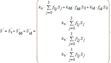
In this paper, circular polarization in the reflection is assumed to be insignificant for a general understanding of most naturally illuminated surfaces.[12] This assumption reduces the 4 × 4 pBRDF Mueller matrix to a 3 × 3 matrix.
The relationship between the Stokes vectors and pBRDF Mueller matrix is shown as follows:
 | (13) |
 | (14) |
For the case of in-plane scattering (


 | (15) |


Under in-plane scattering condition, 


 | (16) |
The light source is assumed to be unpolarized in the case of passive detection where the Stokes vector of incident light is assumed to be 

 | (17) |
Thus, the DOP expression is given by
 | (18) |
In this section, the DOP expression for polarized illumination is given. DOP0°, DOP45°, DOP90°, and DOP135° are used to express the DOP values in the four incident polarization directions (0°, 45°, 90°, and 135°) respectively. Take 0° incident polarization state for example. The Stokes vector of incident light is 
 | (19) |
Similarly, the DOP expressions for 45°, 90°, and 135° incident polarization states are acquired respectively as follows:
 | (20) |
Two metallic materials: Al and Cu are selected for our measurement. The surface roughness is measured by Dimension ICON piezoresponse force microscope which is produced by BRUCKER Corporation. The surface roughness values of Al and Cu are 

In the experiment, the distance between light sources and the measured sample, and the distance between light power meter and the measured sample are kept at constant values in different angles. Thus the paths of both light source and light power meter are two semicircles with one center of circle. The polarizer 1 in front of the light source is used to generate different polarization states. The polarizer 2 in front of the light power meter is used to measure the intensity of reflected light in 0°, 45°, 90°, and 135° polarization states. Firstly, the light source is fixed to in the direction in which the sample surface is illuminated vertically (θi = 0°), the reflected light from sample surface is received by the moving light power meter when the reflected angle ranges from 0° to 80°. Then, the location of light source is changed in steps of 10° and the operation of the light power meter repeats the above step until the distribution of the reflected light in the whole plane of incidence is acquired for incident angles ranging from 0° to 80°.
The measured results show that for different material surfaces, the coefficients k
dd and k
id are both the fixed values, while k
s is the function of incident angle θ
i. The parameters in the diffuse reflection are determined by optimization algorithm and we find that σm = 0.7, k
dd = 900, k
id = 25 are the best fit for the both samples. The values of k
s are shown in Table
| Table 1
The ks values of two metallic materials. . |
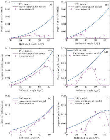
The comparisons between the DOP for P-G pBRDF model and the three-component pBRDF model are shown in Fig.
In Eq. (
The DOP calculated by the three-component pBRDF model is compared with measurements for two metallic samples for four different incident polarization states, and the results are given in
The polarization state of incident light has a little effect on the DOP when incident angle is small for metallic material. However, the distinctions between 0°/90° incident polarization state and 45°/135° incident polarization state are obvious for large incident angles. And the difference of the DOP for each incident polarization direction tends to be large when the incident angle is large. The maximum value of the DOP appears around the direction of specular reflection regardless of incident polarization state. The results show that the DOP based on the three-component model accords well with the experimental results.
A DOP expression is presented based on three-component pBRDF model to improve the existing DOP expression based on the P-G model. Reflected light is divided into specular reflection, directional diffuse reflection, and ideal diffuse reflection. The pBRDF matrix is deduced and DOP expression is given. Compared with the existing DOP expression based on the P-G model, our DOP expression relates to the surface roughness. And the introduction of the diffuse reflection reduces the DOP value and makes simulated DOP closer to the measurement, especially for small incident angle. For unpolarized illumination, the RMS errors of DOP based on the P-G model are reduced by at least 20% for Al and at least 25% for Cu, respectively. For polarized illumination, the simulations match well with the measurements. The results indicate that the incident polarization state has a little effect on the DOP for small incident angle while the distinction is obvious for large incident angle. Therefore, the DOP expression based on the three-component pBRDF model is more reasonable and can depict the polarized reflection characteristics of metallic materials more accurately.
| [1] | |
| [2] | |
| [3] | |
| [4] | |
| [5] | |
| [6] | |
| [7] | |
| [8] | |
| [9] | |
| [10] | |
| [11] | |
| [12] |


