|
(color online) (a) Relation between
 and
and
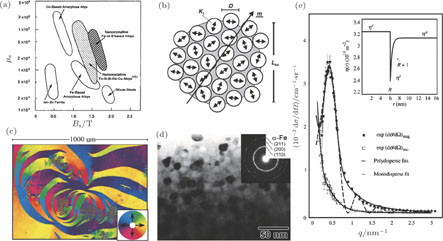
 at 1 kHz for amorphous Fe and Co based alloys, nano-crystalline Fe–M–B based alloys, nano-crystalline Fe–Si–B–Nb–Cu alloys, Mn–Zn ferrite, and silicon steels.[193] With permission from Materials Transactions. Copyright 1995 the Japan Institute of Metals and Materials. (b) Schematic representation of the random anisotropy model for grains embedded in an ideally soft ferromagnetic matrix. The double arrows indicate the randomly fluctuating anisotropy axis; the hatched area represents the ferromagnetic correlation volume determined from the exchange length
 within which the orientation m of the magnetization is constant.[195] With permission from Acta Materialia. Copyright 2013 Elsevier. (c) SEMPA image of the magnetization direction (color) and topography from the air side of an as-cast amorphous ribbon. The magnetization direction is color coded to the color wheel in the inset. The ribbon’s long axis is horizontal.[208] With permission from Journal of Magnetism and Magnetic Materials. Copyright 2000 Elsevier. (d) Bright field image and SAED patterns of nano-crystalline Fe
 Si4B8P4Cu
 alloy.[242] With permission from Materials Transactions. Copyright 2009 The Japan Institute of Metals and Materials. (e) Experimental small-angle neutron scattering data and fits for the Fe
 Si
Si
 B7CuNb3 system with 2 vol.% Fe80Si20 precipitates. The inset shows the magnetic scattering length density.
 ,
,
 , and
, and
 , are the magnetic scattering length density of the core, shell, and amorphous matrix, respectively.[248] Reproduced with permission of the International Union of Crystallography.
|