Nonlinear control of spacecraft formation flying with disturbance rejection and collision avoidance
Ni Qing, Huang Yi-Yong, Chen Xiao-Qian
College of Aerospace Science and Engineering, National University of Defense Technology, Changsha 410073, China


† Corresponding author. E-mail: chenxiaoqian@nudt.edu.cn

Project supported by the National Natural Science Foundation of China (Grant No. 11404404).

Abstract

A nonlinear controller for disturbances rejection and collision avoidance is proposed for spacecraft formation flying. The formation flying is described by a nonlinear model with the J2 perturbation and atmospheric drag. Based on the theory of the state-dependent Riccati equation (SDRE), a finite time nonlinear control law is developed for the nonlinear dynamics involved in formation flying. Then, a compensative internal mode (IM) control law is added to eliminate disturbances. These two control laws compose a finite time nonlinear tracking controller with disturbances rejection. Moreover, taking safety requirements into account, the repulsive control law is incorporated in the composite controller to perform collision avoidance manoeuvres. A numerical simulation is presented to demonstrate the effectiveness of the proposed method. Compared to the conventional control method, the proposed method provides better performance in the presence of the obstacles and external disturbances.

1. Introduction

Spacecraft formation flying (SFF) is a concept that involves accomplishing space missions with multiple spacecrafts in designed arrays. SFF has many advantages over the traditional monolithic spacecraft system. It enables various space missions with enhanced reliability, flexibility, and efficiency. One notable mission involving the formation concept is the Defense Advanced Research Projects Agency's (DARPA) F6 program. This mission is to perform a common objective via distributed satellite operations. [1] SFF was developed as a revolutionary technique by NASA and ESA, used in the PRISMA mission, [2] TPF-I, [3] etc. Regardless of the broad prospects of SFF, technological challenges come with increased complexity, such as efficient fuel cost, precise formation control, and flying safety requirements. Efficient fuel cost is critical to any space mission, while high accuracy in control makes it possible to execute various space formation missions. Additionally, the collision avoidance problem is an important issue when formation reconfiguration is being carried out by multiple spacecraft manoeuvres in close range.

Many researchers have made significant contributions in the field of spacecraft formation control. The most popular model for formation flying is based on the Clohessy & Wiltshire (CW) [4] or Tschauner & Hempel (TH) [5] equation. Following this linear scheme, different methods have been proposed for formation flying. [68] To further improve the accuracy of control, investigations on nonlinear models and control strategies have begun in recent years. New nonlinear control techniques, such as sliding mode (SM), [9] recursive backstepping, [10] and nonlinear adaptive control [11, 12] have been investigated. During the last decade, the state-dependent Riccati equation (SDRE) has been a popular method for the design of controllers used in nonlinear systems. [13] It changes the nonlinear system to a pseudo-linear structure, which has state-dependent coefficient (SDC) matrices. Thus, the classical optimal control theory can be applied to the SDC matrices. This technique has been extended to spacecraft control. [14] For the tight formation reconfiguration, fast convergence is desirable. Compared to other finite time control methods, [15] SDRE could achieve finite time control and nonlinear optimal control simultaneously. An approximate closed-loop solution to optimally control spacecrafts with a finite time cost function was developed for the Reusable launch vehicle. [16] Therefore, the SDRE technique is an alternative method for nonlinear finite time optimal control.

For the spacecraft formation control, the state tracking accuracy should be guaranteed even in the presence of disturbances. An adaptive control architecture that rejects disturbances was proposed to solve the problem of tracking a manoeuvring target. [17] Using mean relative states, a nonlinear controller was derived for a pair of formation flying satellites, which includes the J 2 effect in system dynamics. [18] Based on second-order SM, a nonlinear controller was proposed for spacecraft formation flying in the presence of nonlinear dynamics and J 2 perturbations. [19] In the broad control area literature, an approach based on the Internal Mode (IM) principle has been developed to track the reference trajectory asymptotically and reject disturbances in uncertain nonlinear systems. [20, 21] Based on the IM principle, robust servo-regulators for uncertain satellite-systems were developed; these regulators were capable of eliminating the harmonic fluctuations caused by disturbance forces. [22] The IM principle has great advantages regarding disturbances rejection for formation tracking.

Flying safety requirements, such as path constraint requirements or collision avoidance, constitute an important and fundamental goal in spacecraft formation. Consequently, they have been actively studied by researchers in the control community. An analytical model of a predictive controller for fuel-minimised, collision-free trajectory has been cited in the literature. [23] Compared to other methods like semi-definite programming [24] or optimization-based methods, [25] artificial potential field (APF) guidance is considered an effective method to deal with safety issues. It has been used extensively in robot navigation and control [26, 27] and further extended to orbital vehicles. The autonomous on-orbit assembly of the large space structure has been presented using a superquadric APF. [28] By employing special potential functions and a time-varying sliding manifold, reference [29] studied target tracking, obstacle avoidance, and formation keeping. Based on potential functions and sliding manifolds, two control algorithms were proposed for formation flying with collision avoidance and disturbances rejection. A Riccati based tracking controller with collision avoidance has been presented for spacecraft formation flying near elliptic reference orbits. [30]

Nevertheless, only a few of the aforementioned works take the requirement of obstacle avoidance, finite time optimal control, and disturbances rejection into consideration simultaneously. Furthermore, the problem of finite time tracking with collision avoidance becomes more complex and difficult when designing control systems. Motivated by this open issue, formation flying, including the finite time approach, disturbances rejection, and collision avoidance, is to be considered in this work. The spacecraft proximity motion is described by nonlinear equations. Then, the SDRE method is adopted to solve the nonlinear control problem via SDC transforms. Because of its linear-like structure, IM is integrated to eliminate disturbances. Finally, the collision avoidance strategy is incorporated to form a composite control law. This composite controller is designed to achieve control objectives. As opposed to the work in [29], SDRE and IM are integrated instead of the SM, and the repulsive forces are defined in terms of two items. Reference [30] used the linear model, and disturbances were not considered; a different potential function was analysed. The major contributions of this study are summarised as follows: (i) the nonlinear model is converted into a pseudo-linear like form via SDC; (ii) the IM controller is integrated with the SDRE-based controller for finite time optimal control and disturbances rejection; (iii) flying safety is guaranteed by virtual repulsive forces in terms of both position and velocity.

The structure of this paper is as follows. Section 2 presents the nonlinear relative dynamic equations with J 2 perturbance and atmospheric drag. Then, in section 3, the finite time optimal controller with disturbances rejection and collision avoidance is developed. Numerical simulations are presented in section 4 to demonstrate the effectiveness of the proposed method. Finally, the conclusions of this work are presented in Section 5.

2. Problem formulations
2.1. Nonlinear equations of relative motion

Consider multiple spacecrafts in Low Earth Orbit (LEO), where one of them is defined as the reference spacecraft, and the others are called followers. The relative dynamics of formation flying is described in the Local Vertical Local Horizontal (LVLH) frame. The LVLH frame is denoted by , with its origin located at the centre of the reference spacecraft. The axis points from the Earth's centre towards the reference spacecraft; the axis is perpendicular to the orbital plane and points in the direction of the angular momentum vector. Finally, the axis completes the right-handed orthogonal triad. Throughout this paper, except in special illustrations, every three-dimensional column vector is written in the coordinate form to represent the components along each axis in the LVLH frame.

Let and denote the position and velocity vector of the i-th spacecraft in the LVLH frame; then, the nonlinear relative motion dynamics with perturbations can be described as follows: [31]

(1)
(2)
with
where is the true anomaly of the reference spacecraft, is the distance between the reference spacecraft and the Earth's centre, μ is the gravitational constant of the Earth, m i is the mass of the i-th spacecraft, r i is the distance between the i-th spacecraft and the Earth's centre, is the disturbance acceleration, and is the control acceleration. Note that if the inter-satellite distance is in the order of 1 km, the above model has high fidelity and is adaptive to any eccentric orbit. For the sake of conciseness, the notations and are used to simplify formulations.

The rate of the true anomaly of the reference spacecraft is given by [32]
(3)
where is the mean motion of the reference spacecraft, is the semi-major axis of the reference orbit, and is the orbit's eccentricity. Thus, the differentiation of Eq. (3) results in the rate of change of the true anomaly,
(4)

2.2. Disturbance descriptions

Disturbances are considered for a more precise relative dynamics. Some causes of external disturbances are the Earth's oblateness effect, atmospheric drag, and solar radiation pressure. For the spacecrafts in LEO ( km), friction with residual atmosphere could not be neglected. Among these perturbations, the Earth's oblateness and atmospheric drag are dominant. [33] These two major perturbations are considered in the nonlinear model. The relative J 2 perturbation acceleration acting on the i-th spacecraft is given by the gradient term [34]

(5)
with
where J 2 is the second zonal harmonic coefficient of the Earth, is the radius of the Earth, i is the orbit inclination, u denotes the argument of latitude and has the relation , and ϖ is the argument of perigee.

The relative effect of the atmospheric drag acting on the i-th spacecraft is obtained as [33]

(6)
where .

Thus, the total disturbance acceleration , consisting of the J 2 term and atmospheric drag term, is

(7)

3. Control law design
3.1. Control objective

The control objective is to acquire a geometric formation configuration. The predetermined configuration considers each spacecraft in formation to be on one of the vertices of an equilateral triangle. Therefore, the reference spacecraft is also assumed to be on one vertex of the triangle. The goal is to design a closed-loop controller such that: (i) the other two spacecrafts reach the destination point at a specified time to form a triangular configuration; (ii) the disturbances are well rejected in the manoeuvring process as well as at the configuration point; (iii) no collision contact occurs when reconfiguration manoeuvres are executed.

The following assumptions are made for the synthesis of the control law. (i) The mass change in the i-th spacecraft is assumed to be small during the manoeuvre; thus m i could be assumed to be known and constant in the mission. (ii) Orbital elements of the spacecraft and the formation navigation information could be measured accurately and obtained in time. [35]

3.2. Nonlinear control and SDC parameterization

In this subsection, the SDRE principle and the SDC matrices are presented for nonlinear control. The nonlinear control law design is applied using the state space representation. The normal input-affine nonlinear system of the first-order differential state equation has the following form:

(8)
where is the state vector, is the control acceleration, and and represent the nonlinear dynamics. Generally, the state vector consists of the relative position and velocity components.

The finite time linear state-dependent quadratic cost function of the state and control vectors are defined as follows:

(9)
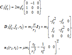
where and are the weighting matrices on the states and control input respectively. Equation (8) could only be used to solve the linear control problem. The SDRE strategy provides an effective algorithm for synthesizing nonlinear feedback controls by allowing nonlinearities in the system states. [36] To solve the nonlinear optimal control problem, the dynamic equation (Eq. (2)) is written as a pseudo-linear structure by first using SDC parameterization
(10)
The state vector is given by for the position manoeuvres. is formulated as
(11)
where

The following assumption is made to obtain a closed loop solution using the SDRE method: [37] and are point-wise stabilized and observable for all in the domain of interest, where is the Cholesky decomposition of . The controllability and observability are checked based on the rank of the controllable and observable matrices.

Then, the following equation is solved to obtain the optimal control input

(12)
with and the final condition .

In the finite time case, the solution is a time-dependent differential equation rather than an algebraic one. For the position control of the formation, a finite time controller is designed based on the SDRE method. According to the finite time analytical approach, [38] the control acceleration is calculated as follows:

(13)

3.3. IM-based control law

This subsection explains the process of designing a controller to reject the unknown disturbances and track the reconfiguration point. Figure 1 shows the proposed closed-loop structure. The state error is considered first. Then, the IM Control (IMC) part is followed by the finite time nonlinear optimal control law, which was discussed in the previous subsection.

Fig. 1. The closed-loop structure of tracking control.

Generally, the disturbance consists of two parts: structure part and non-structure part. The structure part is the dynamic model of the disturbance, and the non-structure part is the magnitude gain. The system equation of the IMC is written as

(14)
where is the 6-dimensional state vector of the i-th spacecraft, is the tracking error, is the dynamic system of the disturbance signals, and is the desired state. The finite time optimal tracking problem can be converted to a finite time regulation problem by defining the state vector . The nonlinear system equation of the real model is described by
(15)
where is the 6-dimensional state vector of the i-th spacecraft, is the control input, is the disturbance signal, and is the dynamic function of real plant.

The original state can be extended to the components of a larger vector in an exogenous state. Defining the augmented state vector , , the nonlinear closed-loop system is given by

(16)
where

The IMC gain and the state feedback gain are specified by and . Then, the tracking control law is defined as

(17)
The tracking control law consists of two parts: the state feedback control law and the IM control law . The state feedback controller tracks the reference state, and the IM controller rejects the unknown disturbances.

3.4. Collision avoidance control law

Collision avoidance during manoeuvres is achieved using high potential values to denote the forbidden areas. The vehicle could move away from the forbidden areas along the negative gradient of the APF. In space missions, the forbidden areas would be other space vehicles, path constraints, etc. To avoid a moving object, an intuitive scheme that takes into account the relative position and velocity components was designed by [41]. Owing to the symmetry of the Gaussian function and the spherical shape of obstacles, the proposed repulsive potential function is selected to be in a Gaussian form

(18)
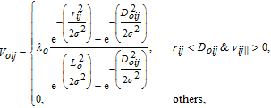
where is a positive constant that shapes the repulsive potential magnitude, is the distance between the i-th spacecraft's position and the j-th spacecraft's position , is the standard deviation of the bell-shaped curve, D oij is the radius of the j-th spacecraft's influence region, and L o is the radius of the spacecraft's exterior surface. is the relative parallel velocity between the i-th spacecraft and the j-th spacecraft, given by
(19)
where and are the corresponding velocities of the i-th spacecraft and j-th spacecraft, is the unit vector pointing from the i-th spacecraft to the j-th spacecraft and . If , the i-th spacecraft is flying away from the j-th spacecraft and no avoidance action is needed; otherwise, the i-th spacecraft is moving towards the j-th spacecraft; then, the avoidance manoeuvre must be executed within the influence region of thej-th spacecraft.

The influence region of the j-th spacecraft is defined as follows:

(20)
where d o is the constant multiple factor, D sij is the minimum stopping distance, determined as
(21)
where is the maximum acceleration allowed by the control actuator.

The perpendicular velocity between the i-th spacecraft and the j-th spacecraft is defined as
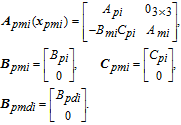
(22)
where is the magnitude of the velocity vector and is the unit vector perpendicular to .

The corresponding repulsive force is defined as the negative gradient of the repulsive potential with respect to the position and velocity terms,
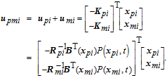
(23)
with

The corresponding derivatives are computed as follows:

, , and are defined to simplify the representation. Thus, the gradient of the repulsive potential is
(24)
Therefore, the repulsive force generated by the j-th spacecraft is given by
(25)
with
The following conditions are satisfied by formulas deriving.

,

, ,

, ,

, .

Thus,
Therefore, the parallel force is along the negative direction of and stops the i-th spacecraft from moving closer to the j-th spacecraft. The perpendicular part is in the same direction as and steers the i-th spacecraft for detouring.

3.5. The composite control law

In this subsection, the process of designing a nonlinear feedback controller for achieving the control objectives is discussed. Given the relative motion described by Eq. (16) under disturbances given in Eq. (7), the control structure is designed as shown in Fig. 2. The following composite controller enables the system to achieve the control objectives discussed in Section 3.1.

(26)
where is calculated using Eq. (17). The repulsive acceleration is the sum of all the repulsive effects and is given by
(27)
where n is the number of the spacecraft and is the repulsive force generated by the j-th spacecraft.

Fig. 2. Nonlinear closed-loop control structure.
3.6. Numerical results and analysis

In this section, simulation results are presented for the formation flying control. As a demonstration of the proposed approach, a formation manoeuvre scenario is considered. In addition, two comparison scenarios are utilized to justify the performance. Table 1 gives the physical parameters of the spacecraft. Table 2 summarises the orbital elements. The reference orbit is the sun-synchronous orbit, which has an approximate altitude of 400 km. Table 3 lists the symbols used in the simulations.

Table 1.

Physical parameters of the spacecraft.

.
Table 2.

Parameters for the reference orbit.

.
Table 3.

Symbols used in the simulations.

.
3.7. Scenario 1: Equilateral triangle formation reconfiguration

In this scenario, the desired triangle formation configuration has a 1000 m length on each edge. Table 4 gives the parameters used in the scenario, which are described in the LVLH frame. S1 is assumed to be static and located at a vertex of the triangle. S2 and S3 carry out manoeuvres to the destination point. The spacecraft in the influence range of colliding is considered an obstacle. The simulation is implemented using the model described in Eq. (16) and the control law according to Eq. (26). The following weighted matrices are selected: , and .

Table 4.

Parameters used in the simulation.

.

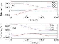
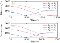
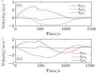
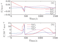
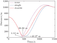
As shown in Fig. 3, the formation shape converges to the desired pattern in less than 1500 s. Figure 4 shows the relative distances between the spacecrafts in the formation. It can be seen that the distance between S2 and S3 becomes shorter in the early phase. The distance is close to the minimum value (38.87 m) at around 465 s. Then, the relative distance rapidly increases with the repulsive force. The other relative distances in the formation are greater than those specified in the safety requirements. The minimum distance between any two spacecrafts is never less than 10 m; thus, no collision occurs. Figure 5 indicates that the velocities of the two manoeuvring spacecrafts in the formation converge to the desired values within 1500 s. The control input histories are shown in Fig. 6. When S2 is moving ahead of S3 or out of the influence range of S3, S3 does not have repulsive effect on S2. Once S2 enters into the influence range of S3, S3 is considered as the obstacle, and S2 needs to detour around it. Thus, the velocity and control accelerations change rapidly to execute the avoidance manoeuvre in the obstacle influence range. It indicates that the control magnitudes are at the proper level and do not exceed the spacecraft's maximum drive capability.

Fig. 3. (color online) Position histories of the manoeuvring spacecrafts (a) S2 and (b) S3.
Fig. 4. (color online) Distances between the spacecrafts in formation.
Fig. 5. (color online) Velocity histories of spacecrafts (a) S2 and (b) S3 in formation.
Fig. 6. (color online) Control accelerations of spacecrafts (a) S2 and (b) S3 in formation.
3.8. Scenario 2: Comparison of the control strategies

To validate the theoretical analysis, the controller with single repulsive force control [42] is verified and compared with the proposed controller in Eq. (26). Note that only the repulsive control parts are compared; the other control parts are selected to be identical for these two control strategies. The simulation conditions are the same as those in scenario 1.

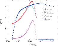
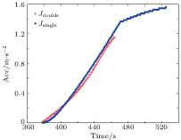
The relative distances between the spacecrafts are shown in Fig. 7. The non-repulsive control case is selected as an auxiliary statement. The minimum distance with non-repulsive force is 4.44 m, which is less than the safe distance. Without the repulsive force, collision occurs. The distance results indicate that flying safety could be guaranteed by both the repulsive control strategies. The repulsive forces for two cases (described in the LVLH frame) are shown in Fig. 8. For the double repulsive force case, when S2 enters into the influence range of S3, S3 generates two kinds of repulsive forces: the parallel part (cyan line) that decreases the velocity pertaining to S3; the perpendicular part (magenta line) that changes S2's velocity direction such that S2 makes a detour around S3. At the same time, S3 enters the influence range of S2, and a similar set of repulsive forces act on S3. The red line is the magnitude of the repulsive force generated by the double repulsive force method. The blue line shows the magnitude of the singular repulsive force. There is little difference in magnitude between the two kinds of forces. The obvious differences are the effect time and the trends. Both the strategies begin to have an effect at 379 s. However, the end times are not the same. One is at 465 s, and the other is at 526 s. Thus, the two cases have an effect time of 86 s and 147 s, respectively. The corresponding fuel cost is shown in Fig. 9. The cost of the single repulsive force strategy is 1.57 and that of the double repulsive force strategy is 1.15. From Figs. 7 and 9, it can be seen that the control strategy involving double repulsive force is more desirable.

Fig. 7. (color online) Separation distances between the spacecraft.
Fig. 8. (color online) Repulsive forces generated in avoidance process.
Fig. 9. (color online) Fuel cost of two avoidance strategies.
3.9. Scenario 3: Formation keeping

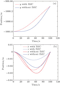
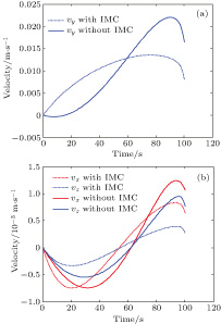
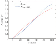
In this scenario, a comparison of IMC and non-IMC control strategies is made to show the effectiveness of the IMC controller. This scenario takes spacecraft S2 as an example. To evaluate the control method effectively, the comparison is made under an identical situation. The two spacecrafts have identical physical characteristics. The parameters of the orbit and spacecraft are given in Tables 2 and 1, respectively. As the relative J 2 and atmospheric forces are functions of the relative position, the disturbance accelerations become smaller with decreasing distance. To show the disturbances rejection effect, the initial position is set at the position with zero relative velocity in the LVLH frame. The formation-keeping point is assumed to be located at . The simulation time length is set for 1000 s, and the sampling interval is 1 s. Figure 10 and 11 show the positions and velocity results of the two controllers, respectively. It can be seen that the effect of the IMC controller becomes obvious with disturbances. The convergence with IMC is faster, and the error magnitudes are smaller than those without IMC. The running fuel cost is indicated in Fig. 12. It costs for the non-IMC case and for the IMC case. In the IMC case, the fuel cost is higher in the early phase, but the increasing trend is even. Therefore, the control strategy with IMC is more efficient.

Fig. 10. (color online) Position comparison of IMC and Non-IMC.
Fig. 11. (color online) Velocity comparison of IMC and Non-IMC.
Fig. 12. (color online) Fuel cost of two strategies.
4. Conclusions

A composite control strategy has been proposed for spacecraft proximity operations. The design of the composite controller was divided into three parts. First, the dynamical model was converted into an approximately linear form via the SDC method, and the finite time suboptimal control law was designed based on the SDRE theory. Second, the IMC was integrated to reject the unknown disturbances. Finally, a composite control scheme was obtained by adding the APF control part. Forces in two different directions were generated to enhance the repulsive effect. The formation reconfiguration simulation was conducted to demonstrate the effectiveness of the proposed controller. Two additional comparisons were made to show the enhanced performance in collision avoidance and disturbance rejection.

Reference
1 Brown O Eremenko P Bille M 2009 Proceedings of 23th Annual conference on small satellite August 10–13, 2009 Logan,Utah, SSC09-I-1
2 D’Amico S Ardaens J S Larsson R 2012 Journal of Guidance, Control, and Dynamics 35 834
3 Scharf D P Keim J A Hadaegh F Y 2010 IEEE Systems Journal 4 84
4 Clohessy W H Wiltshire R S 1960 Journal of Aerospace Science 27 653
5 Tschaune J Hempel P 1965 Astronautica Acta 11 104
6 Kapila V Sparks A G Buffington J M Yan Q 2000 Journal of Guidance, Control, and Dynamics 23 561
7 Mok S H Choi Y H Bang H C 2010 International Journal Aeronautical and Space Sciences 11 351
8 Li J Xi X N 2012 Journal of Guidance, Control, and Dynamics 35 1709
9 Liu H Li J Hexi B 2006 Aerospace Science and Technology 10 636
10 Lim H C Bang H 2009 Acta Astronaut 65 112
11 De Queiroz M S Kapila V Yan Q 2000 Journal of Guidance, Control, and Dynamics 23 385
12 Jia H Qun-Jiao Z 2008 Chin. Phys. B 17 503
13 Cimen T 2012 Journal of Guidance, Control, and Dynamics 35 1025
14 Massari M Zamaro M 2014 Acta Astronaut 94 409
15 Lan Q Yang J Li S Sun H 2015 Journal of Aerospace Engineering 28 04014137
16 Heydari A Balakrishnan S 2013 Journal of Guidance, Control, and Dynamics 36 1210
17 Stepanyan V Hovakimyan N 2007 Journal of Guidance, Control, and Dynamics 30 1090
18 Kumar B S Eyer J K 2012 Acta Astronaut 77 61
19 Li J Pan Y Kumar K D 2012 Journal of Guidance, Control, and Dynamics 35 309
20 Huang J 1995 IEEE Trans. Autom. Control 40 1118
21 Huang J Lin C F 1994 IEEE Trans. Autom. Control 39 1510
22 Lee K Singh S 2012 Proceedings of AIAA Guidance, Navigation, and Control Conference 4693 August 13–16, 2012 Minneapolis, Minnesota
23 Sauter L Palmer P 2012 Journal of Guidance, Control, and Dynamics 35 1069
24 Frazzoli E Mao Z H Oh J H Feron E 2001 Journal of Guidance, Control, and Dynamics 24 79
25 Qian-Ling W Yao C Hai-Rong D Min Z Bin N 2015 Chin. Phys. B 24 038901
26 Leonard N E Fiorelli E 2001 Proceedings of Proceedings of the 40th IEEE Conference on Decision and Control 2968 Dec 04–07, 2001 Orlando, FL,
27 Rimon E Koditschek D E 1992 IEEE Trans. Robot. Autom. 8 501
28 Badawy A McInnes C R 2008 Journal of Guidance, Control, and Dynamics 31 30
29 Hu Q Dong H Zhang Y Ma G 2015 Aerospace Science and Technology 42 353
30 Palacios L Ceriotti M Radice G 2015 Adv. Space Res. 56 2167
31 Schlanbusch R Kristiansen R Nicklasson P J 2011 Automatica 47 1443
32 Kristiansen R Nicklasson P J 2009 Acta Astronaut 65 1537
33 Morgan D Chung S J Blackmore L Acikmese B Bayard D Hadaegh F Y 2012 Journal of Guidance, Control, and Dynamics 35 1492
34 Schweighart S A Sedwick R J 2002 Journal of Guidance, Control, and Dynamics 25 1073
35 Peng Q Wei C You-Jiany S Ming-Lie H Lu C Ching-Yue W 2012 Acta Phys. Sin. 61 240601 in Chinese
36 Cimen T 2008 Proceedings of Proceedings of the 17th World Congress of the International Federation of Automatic Control (IFAC) 3761 July 6–11, 2008 Seoul, Korea,
37 Mracek C P Cloutier J R 1998 Int. J. Robust Nonlinear Control 8 401
38 Heydari A Balakrishnan S N 2013 Journal of Guidance, Control, and Dynamics 36 1210
39 Nguyen T Gajic Z 2010 IEEE Trans. Autom. Control 55 191
40 Heydari A Balakrishnan S 2015 Int. J. Robust Nonlinear Control 25 2687
41 Ge S S Cui Y J 2002 Auton. Robots 13 207
42 McCamish S B Romano M Nolet S Edwards C M Miller D W 2009 J. Spacecr. Rockets 46 1202