An acoustic bending waveguide designed by anisotropic density-near-zero metamaterial
Wang Yang-Yang1, Ding Er-Liang1, Liu Xiao-Zhou1, 2, †, , Gong Xiu-Fen1
Key Laboratory of Modern Acoustics, Institute of Acoustics, Nanjing University, Nanjing 210093, China
State Key Laboratory of Acoustics, Institute of Acoustics, Chinese Academy of Sciences, Beijing 100190, China


† Corresponding author. E-mail: xzliu@nju.edu.cn

Project supported by the National Basic Research Program of China (Grant No. 2012CB921504), the National Natural Science Foundation of China (Grant No. 11474160), the Fundamental Research Funds for the Central Universities, China (Grant No. 020414380001), the State Key Laboratory of Acoustics, Chinese Academy of Sciences (Grant No. SKLA201609), and the Priority Academic Program Development of Jiangsu Higher Education Institution, China.

Abstract
Abstract

Anisotropic metamaterial with only one component of the mass density tensor near zero (ADNZ) is proposed to control the sound wave propagation. We find that such an anisotropic metamaterial can be used to realize perfect bending waveguides. According to a coordinate transformation, the surface waves on the input and output interfaces of the ADNZ metamaterial induces the sound energy flow to be redistributed and match smoothly with the propagating modes inside the metamaterial waveguide. According to the theory of bending waveguide, we realize the “T”-type sound shunting and convergence, as well as acoustic channel selection by embedding small-sized defects. Numerical calculations are performed to confirm the above effects.

1. Introduction

The acoustic properties exhibited by metamaterials are remarkable, and various amazing phenomena have been discovered in previous studies on metamaterials,[112] such as negative refraction,[1] negative Doppler effect,[2] and acoustic cloaking.[37] Metamaterial with parameters near zero are also an important and intriguing material.[13,14] Due to the fact that the equivalent parameters of metamaterial can be changed by simply adjusting the structure parameters, we can obtain not only the negative-index metamaterial with both negative density and bulk modulus,[1517] but also the zero-index metamaterial (ZIM) with zero density and/or zero reciprocal of bulk modulus.[18,19] Recently, density-near-zero (DNZ) metamaterial and index-near-zero (INZ) metamaterial have aroused growing interest and various applications have been proposed.[2028] Bongard et al. achieved acoustic transmission line metamaterial with zero refractive index by membranes and open channels.[20] Jing et al.,[21] Park et al.,[22] and Fleury and Alu[23] achieved near-zero-density metamaterial by using membrane structure both in numerical analysis and experimental verification respectively. In addition, Shen et al. investigated a type of anisotropic, acoustic complementary metamaterial which consists of unit cells formed by membranes and side branches with open ends.[24] Furthermore, Xu et al. designed and fabricated an anisotropic zero-mass acoustic metamaterial lens based on clamped paper membrane units.[25]

Anisotropic DNZ (ADNZ) metamaterial with only one component of the mass density tensor near zero can be used to manipulate the sound transmission in the designed paths. Various prototypes have been demonstrated to manipulate sound transmissions, such as acoustic concentration,[29] and sound transmission through ultranarrow acoustic channels.[30] The bending waveguide effect is one of the especially interesting applications.[3133] For conventional bending waveguide, reflection and the distortion of the wave front are often complex. Many methods have been proposed to minimize the reflection and distortion of waves.[31]

In this paper, we investigate the properties of the ADNZ metamaterial further. First we find that the ADNZ metamaterial can be introduced into a waveguide system to control sound wave propagation and realize perfect bending waveguides. Then we realize the “T”-type sound shunting and convergence which support the multi-channel communication. Furthermore, acoustic channel selection by embedding small-sized defects is also an interesting finding inspired by the theory of a bending waveguide.

2. Simulation results and discussion

As illustrated in Fig. 1, a two-dimensional (2D) acoustic waveguide structure with hard walls consists of an input rectangular waveguide (region 0), an output rectangular waveguide (region 2), and a waveguide junction (region 1). Region 0 (region 2) is the host medium with an effective density of ρ0 and an effective bulk modulus of κ0. The mass density tensor and bulk modulus of the ADNZ metamaterial in region 1 are (ρx, ρy) and κ1 respectively, where ρx and ρy are the x and y components of the mass density tensor.

Fig. 1. The schematic graph of a 2D acoustic waveguide structure, whose input and output waveguides (regions 0 and 2) are filled with water with an effective density of ρ0 = 1000 kg/m3 and an effective bulk modulus of κ0 = 2.25 GPa, consists of an ADNZ metamaterial (region 1). The parallel lines in the x direction are hard walls.

For convenience the time variation item e−jωt is omitted. The velocity field is given by

and

where p is the pressure field, vx and vy are the velocity field components in the x direction and y direction respectively, and ω is the angular frequency. When the condition ρy ≈ 0 is satisfied, ∂p/∂y ≈ 0 is required to obtain the finite velocity. This means that the pressure field p in the ADNZ metamaterial is almost uniform in the y direction. Supposing that ρx is only dependent on the y coordinate, i.e., ρx(y). The impedance of ADNZ metamaterial in the x direction is . The forced uniformity of the pressure field in the y direction in the ADNZ metamaterial exerts a strong averaging effect on the inhomogeneous mass density ρx. In fact, when ηxeff = η0, ADNZ metamaterial is impedance matched to the host medium, thereby making the acoustic wave transmit totally. As ∂p/∂y ≈ 0, we can obtain (ρxvx)/∂y ≈ 0 and the amplitude of the velocity vx(y) should be proportional to 1/ρx(y).

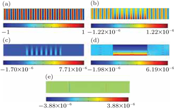
In order to verify our theoretical analysis above, the full-wave simulations are carried out by using the finite element method (FEM). Parameters in the ADNZ metamaterial are set as ρx(y) = ρ0y/[(y1 + y2)/2], ρy = ρ0/1000 and κ1 = κ0, where y1 and y2 are the upper and lower boundary of the waveguide respectively. Figure 2(a) shows that the pressure field p in the ADNZ metamaterial is almost uniform while ρx(y) is a linear function of y. The amplitude of velocity vx(y) in the ADNZ metamaterial decays almost linearly with y, as shown in Fig. 2(b). Figure 2(c) shows the distribution of the velocity in the y direction.

Now we come to explain the mechanism of the acoustic energy propagating from the input interface to the output interface of the ADNZ metamaterial. The time-averaged acoustic energy flux density, also known as the acoustic intensity in the x direction Ix = 0.5Re(vxp*) should be proportional to 1/ρx(y) as vx(y) is proportional to 1/ρx(y) and the pressure is constant. Therefore, the acoustic energy flow in the x direction is larger than in the lower ρx(y) region as shown in Fig. 2(d). One can see that the surface waves on the input and output interfaces of the ADNZ metamaterial are so strong that they can cause the progress of the energy flow redistribution on the interfaces to smoothly connect with the propagating modes inside the ADNZ metamaterial. In order to have a better look at the way the energy flows, figure 2(e) clearly shows the existence of the acoustic intensity in the y direction Iy = 0.5Re(vyp*) at the interfaces between the water and the ADNZ slab, and testifies such surface waves. Hence we can utilize the concentration of the acoustic intensity in the small ρx(y) region to manipulate the way acoustic energy flows in the whole system.

Fig. 2. Field distributions in the straight channel with an ADNZ metamaterial for (a) pressure field p, (b) velocity field in the x direction, (c) velocity field in the y direction, (d) acoustic intensity in the x direction, and (e) acoustic intensity in the y direction.

With the above results of a straight waveguide of ADNZ metamaterial, it would be interesting to investigate the cases for bending waveguides. As illustrated in Fig. 3(a), a 2D acoustic waveguide structure with hard walls consists of an input rectangular waveguide (region 0), an output rectangular waveguide (region 2), and a semicircular waveguide junction (region 1). Region 0 (region 2) is the host medium with an effective density of ρ0 and an effective bulk modulus of κ0. The mass density tensor or bulk modulus of the ADNZ metamaterial in region 1 is (ρr, ρθ or κ0. In order to gain the same phenomenon as that in a rectangular coordinate system, we assume that g(r) = r, g′(r) = 1, ρy ≈ 0, R = (y1 + y2)/2, y1 = 0.5 m, y2 = 1.5 m, and ρx(y) = (y/R)ρwater. According to the coordinate transformation similar to that in Ref. [34], i.e., x = and y = g(r), we can obtain the following expression: ρr = ρyg′(r)r/R and ρθ = ρx(y)R/g′(r)r. Then we can obtain ρr ≈ 0 and ρθ = ρwater. It means that the above straight waveguide is equal to the homogeneous bending waveguide. The impendences of the water and the ADNZ slab are matched in the θ direction, which leads to zero reflection. On the other hand, as ρr ≈ 0, the pressure field is almost uniform in the radial direction. In the cylindrical coordinate system, we can understand the zero reflection on the interface between the ADNZ metamaterial and water. Then, we make numerical simulations using the FEM. As a consequence, the ADNZ metamaterial has the capability of bending and almost totally transmits waves in a channel shown in Fig. 3(b), however, the wave front is distorted when the ADNZ metamaterial is replaced by water as shown in Fig. 3(c).

Fig. 3. (a) Schematic diagram of a 2D acoustic bending waveguide structure. The pressure field distributions with the bending part filled with (b) an ADNZ metamaterial (ρr ≈ 0 and ρθ = ρwater) and (c) water.

Furthermore, it is not limited to the semicircular channel which can make wave propagation perfect, we can make the ADNZ metamaterial into other shapes such as “T” shape as shown in Fig. 4. Ports 1, 2, and 3 are filled with water, and ADNZ metamaterials are placed in the symmetrical corners in Fig. 4(a). When the input source is located in port 1 as shown in Fig. 4(b), it is clear to see that the incident wave successfully separates into two waves, which still keep the shape of the plane wave. More importantly, there is no reflection due to the matched impedances of ADNZ metamaterial and water. Thus the structure should be regarded as a beam splitter. However, if the ADNZ metamaterial is replaced by water, we will find that the reflection and the distortion of wave front are complicated as shown in Fig. 4(c). On the contrary, if the incident waves from ports 2 and 3 are of the same phase, meanwhile the wave numbers are respectively k2 = − 1 and k3 = 1, we will find that these two waves merge into one plane wave perfectly as shown in Fig. 4(d). Similarly, if the ADNZ metamaterial is replaced by water, as a common sense, these two waves will conform to the superposition principle and even disappear as shown in Fig. 4(e). With the theory of a bending waveguide, we can realize the “T”-type sound shunting and convergence.

More interestingly, the total reflection can be achieved by embedding ideal soft defects in ADNZ metamaterial, which can be used to realize an acoustic switch as shown in Fig. 5. Figure 4(b) shows that the incident wave will separate into two waves if there are no defects. However, if there is an ideal soft defect in the above ADNZ metamaterial, we will find that the wave below can transmit successfully, and the above wave is blocked on the surface of the defect as shown in Fig. 5(a). Actually, the sound soft boundary condition induces the pressure to be zero on the surface of an ideal soft defect. Due to the uniformity of the pressure field in the ADNZ metamaterial, a small ideal soft defect can cause the pressure field to be zero, and the incident acoustic wave should be totally reflected by the ADNZ metamaterial, no matter how small in size the defect is. Similarly, if the ideal soft defect is placed in the below ADNZ metamaterial, the wave below will be blocked as shown in Fig. 5(b). Obviously, double blocking will take place when two defects are placed in both ADNZ metamaterials. The defect acts as an acoustic switch: if the defect is added into the channel, the channel is in an “off” state; if the defect is taken away from the channel, the channel is in an “on” state.

Fig. 4. Pressure field distribution in a “T”-shape channel filled with ADNZ metamaterial. (a) The schematic diagram of the “T” channel, where ports 1, 2, and 3 are filled with water, symmetrical corners are filled with ADNZ metamaterial, and their boundaries are hard walls. (b) Transmitting from port 1 to ports 2, 3 and (c) transmitting with ADNZ metamaterial replaced by water. (d) Transmitting from ports 2 and 3 to port 1. (e) Transmitting with ADNZ metamaterial replaced by water.
Fig. 5. Pressure field distributions in a “T”-shape channel filled with ADNZ metamaterial with (a) an ideal soft defect in the above ADNZ metamaterial, (b) an ideal soft defect in the below ADNZ metamaterial, (c) two defects in both ADNZ metamaterials.
3. Conclusions

In this work, perfect bending waveguides with ADNZ metamaterial are realized in theory and in simulation. Theoretical analyses reveal that the key to ensuring the total transmission in bending waveguides is the surface wave, which redistributes the sound energy flow. With the support of the theory of bending waveguide, “T”-type sound shunting and convergence can support multi-channel communication, and the acoustic channel selection which is affected by the small-sized embedded defects can be used to realize acoustic switch. In practical applications, the bending waveguide achieved by anisotropic near-zero parameters can be possibly implemented by employing membrane-type acoustical metamaterial with properly tuned structural parameters, [24,25] which is the goal of our next work.

Reference
1Zhang SYin LFang N2009Phys. Rev. Lett.102194301
2Lee S HPark C MSeo Y MKim C K 2010 Phys. Rev. 81 241102
3Chen HChan C T 2007 Appl. Phys. Lett. 91 183518
4Cheng YYang FXu J YLiu X J 2008 Appl. Phys. Lett. 92 151913
5Cummer S ARahm MSchurig D 2008 New J. Phys. 10 115025
6Farhat MGuenneau SEnoch S 2009 Phys. Rev. Lett. 103 024301
7Zhang SXia CFang N 2011 Phys. Rev. Lett. 106 024301
8Zhu X FLiang BKan WCheng J C 2011 Phys. Rev. Lett. 106 014301
9Zhu X FRamezani HShi C ZZhu JZhang X 2014 Phys. Rev. 4 031042
10Zhu X F 2013 Phys. Lett. 377 1784
11Dai D DZhu X F 2013 Europhys. Lett. 102 14001
12Zhao D GLi YZhu X F 2015 Sci. Rep. 5 9376
13Wei QCheng YLiu X J 2013 Appl. Phys. Lett. 102 174104
14Gu Z MLiang BZou X YYang JLi YYang JCheng J C 2015 Appl. Phys. Lett. 107 213503
15Li JChan C T 2004 Phys. Rev. 70 055602
16Ding YLiu ZQiu CShi J 2007 Phys. Rev. Lett. 99 093904
17Lee S HPark C MSeo Y MWang Z GKim C K 2010 Phys. Rev. Lett. 104 054301
18Zhou XHu G 2011 Appl. Phys. Lett. 98 263510
19Liu FHuang XChan C T 2012 Appl. Phys. Lett. 100 071911
20Bongard FLissek HMosig J R 2010 Phys. Rev. 82 094306
21Jing YXu JFang N X 2012 Phys. Lett. 376 2834
22Park J JLee K J BWright O BJung M KLee S H 2013 Phys. Rev. Lett. 110 244302
23Fleury RAlu A 2013 Phys. Rev. Lett. 111 055501
24Shen CXu JFang N XJing Y 2014 Phys. Rev. 4 041033
25Xu XLi PZhou XHu G 2015 Europhys. Lett. 109 28001
26Ding E LWang Y YLiu X ZGong X F 2015 AIP Adv. 5 107222
27Cheng QCai B GJiang W XMa H FCui T J 2012 Appl. Phys. Lett. 101 141902
28Cheng QJiang W XCui T J 2012 Phys. Rev. Lett. 108 213903
29Liu FCai FPeng SHao RKe MLiu Z 2009 Phys. Rev. 80 026603
30Fleury RAlù A 2013 Phys. Rev. Lett. 111 055501
31Wu L YChen L W 2011 J. Appl. Phys. 110 114507
32Li XLiu Z 2005 Phys. Lett. 338 413
33Jiang XLiang BZou X YYin L LCheng J C 2014 Appl. Phys. Lett. 104 083510
34Liang ZLi J 2011 Opt. Express 19 16821