Turbulence mitigation scheme based on multiple-user detection in an orbital–angular-momentum multiplexed system
Zou Li1, 2, Wang Le1, Zhao Sheng-Mei1, 3, †, , Chen Han-Wu4
Institute of Signal Processing and Transmission, Nanjing University of Posts and Telecommunications, Nanjing 210003, China
School of Electronics and Information, Nantong University, Nantong 226000, China
Key Laboratory of Broadband Wireless Communication and Sensor Network Technology of Ministry of Education, Nanjing University of Posts and Telecommunications, Nanjing 210003, China
School of Computer Science and Engineering, College of Software Engineering, Southeast University, Nanjing 210096, China


† Corresponding author. E-mail: zhaosm@njupt.edu.cn

Project supported by the National Natural Science Foundation of China (Grant Nos. 61271238 and 61475075), the Open Research Fund of Key Lab of Broadband Wireless Communication and Sensor Network Technology, Ministry of Education, China (Grant No. NYKL2015011), the Postgraduate Innovation Research Plan of Jiangsu Province, China (Grant No. CXZZ13_0489), and the University Natural Science Foundation of Jiangsu Province, China (Grant No. 16KJB510037).

Abstract
Abstract

Atmospheric turbulence (AT) induced crosstalk can significantly impair the performance of a free-space optical (FSO) communication link using orbital angular momentum (OAM) multiplexing. In this paper, we propose a multiple-user detection (MUD) turbulence mitigation scheme in an OAM-multiplexed FSO communication link. First, we present a MUD equivalent communication model for an OAM-multiplexed FSO communication link under AT. In the equivalent model, each input bit stream represents one user’s information. The deformed OAM spatial modes caused by AT, instead of the pure OAM spatial modes, are used as information carriers, and the overlapping between the deformed OAM spatial modes are computed as the correlation coefficients between the users. Then, we present a turbulence mitigation scheme based on MUD idea to enhance AT tolerance of the OAM-multiplexed FSO communication link. In the proposed scheme, the crosstalk caused by AT is used as a useful component to deduce users’ information. The numerical results show that the performance of the OAM-multiplexed communication link has greatly improved by the proposed scheme. When the turbulence strength is 1 × 10⁻¹⁵ m−2/3, the transmission distance is 1000 m and the channel signal-to-noise ratio (SNR) is 26 dB, the bit-error-rate (BER) performance of four spatial multiplexed OAM modes lm = +1,+2,+3,+4 are all close to 10−5, and there is a 2–3 fold increase in the BER performance in comparison with those results without the proposed scheme. In addition, the proposed scheme is more effective for an OAM-multiplexed FSO communication link with a larger OAM mode topological charge interval. The proposed scheme is a promising direction for compensating the interference caused by AT in the OAM-multiplexed FSO communication link.

1. Introduction

Orbital angular momentum (OAM) is identified by the angular distribution of its wave phase front.[1] Generally, a laser beam with a helical phase front, i.e., containing a phase term of exp(i), carries an OAM value of on each of its photons, where l is an unbounded integer indicating the topological charge, θ is a azimuthal angle, and ħ is the reduced Plank’s constant.[2,3] In this context, research studies have shown that an increase of both channel capacity and spectral efficiency can be achieved by exploiting the orthogonality phenomenon among different OAM modes.[4] The OAM multiplexing technique has been extensively studied in both free-space optical (FSO) communication systems and fiber communication systems.[514]

One limitation of the FSO communication link is known as the atmospheric turbulence (AT) induced signal degradation.[1517] The purity of an OAM mode is susceptible to spatial aberrations caused by AT when data-carrying OAM beams are transmitted through an AT aberrated channel.[1821] Part of the energy would be spread from one OAM mode to other OAM modes after the turbulent propagation. Consequently, AT causes both errors for a single OAM mode and time-varying crosstalk among different OAM modes.[22] It is shown that these errors and interference significantly impair performance of an OAM-multiplexed FSO communication link.[23] Subsequently, several methods have been presented to mitigate the crosstalk caused by atmospheric turbulence in the OAM-multiplexed FSO communication link.[2429] For example, a wavefront correction method has been used to compensate the deformation caused by AT.[2426] A low density parity check (LDPC) coding method has been used to reduce the OAM modal crosstalk induced by AT in Ref. [27]. We proposed a channel coding scheme to mitigate AT interference and achieved a big improvement in the performance of the AT interference systems.[28] In addition, a multiple-input-multiple-output (MIMO) adaptive equalization method has been used to mitigate crosstalk degradation in an OAM-multiplexed FSO communication link.[29] In all of the above turbulence mitigation methods, however, the crosstalk caused by AT is regarded as a noise to the communication system and the noise is restrained rather than utilized in the systems’ information detection.

In a different context, the multiple-user detection (MUD)[30,31] technique provides a good solution both for the joint detection of all the interfering signals[32] and the single-user detection. In addition, it is robust against the multiuser interference and the background noise. It has been verified that it is an effective way to mitigate multiple access interference and fading effect in wireless communication systems.[33] Currently, a lot of MUD algorithms have been designed to utilize the interference among the multiple users to obtain the optimum sending information, such as the optimum MUD algorithm,[34] de-correlating detection linear MUD algorithm,[35] minimization of mean-square-error(MMSE) detection linear MUD algorithm,[36] blind adaptive detection algorithm,[37] non-linear MUD detection algorithm,[38] and neural network detection algorithm.[39] In each MUD algorithm, the interference is used as a useful component for detecting the users’ information.

In this paper, we present a turbulence mitigation scheme based on MUD idea in the OAM-multiplexed FSO communication link. Here, the crosstalk caused by AT is utilized as a useful component instead of an interference and it is used to obtain the sending information. Firstly, an equivalent MUD model for the OAM-multiplexed FSO communication link disturbed by AT is presented. In the equivalent model, each input bit stream represents one user’s information, the deformed OAM modes caused by AT, which are the substitutes of the pure OAM modes, are used as information carriers to modulate each user’s information. The problem caused by AT in the turbulent aberration channel is now changed to the problem of modulating users’ information with the deformed OAM modes at the transmitter. The overlapping between the deformed OAM modes are computed as the correlation coefficients. Subsequently, the de-correlating detection method is adopted to detect the users’ sending information. The performance of the OAM-multiplexed communication link is discussed with and without the proposed mitigation scheme.

The rest of the paper is organized as follows. In Section 2, the theoretical analysis of the equivalent MUD model for the OAM-multiplexed FSO communication link disturbed by AT is presented, and the de-correlating MUD detection method is used to solve the problem. In Section 3, simulation environment of the turbulence model and the turbulence mitigation scheme based on MUD is firstly given. Then, the performance of the OAM-multiplexed FSO communication link is discussed with and without the proposed turbulence mitigation scheme. The conclusions are given in Section 4.

2. A turbulence mitigation scheme based on MUD in the OAM-multiplexed FSO communication link

In this section, an equivalent MUD model for the OAM-multiplexed FSO communication link disturbed by AT is presented, and subsequently the de-correlating MUD detection method is used to solve the MUD detection problem.

2.1. The equivalent model of OAM-multiplexed FSO communication link through atmospheric turbulence

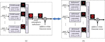
A schematic diagram of an equivalent MUD model for the OAM-multiplexed FSO communication link disturbed by AT is shown in Fig. 1, where figure 1(a) is the OAM-multiplexed FSO system disturbed by AT, figure 1(b) is an equivalent MUD system model. In Fig. 1(a) we assume that each user has an input bit stream and that each input is an information-carrying Gaussian beam with planar phase front in a multilevel amplitude/phase modulation format. A spiral phase mask in an OAM mode converter transfers the input planar phase front to a helical one, resulting in the generation of an OAM spatial mode, labelled by LGl1(r,θ), LGl2(r,θ),…, LGlN(r,θ), where LGlm(r,θ), m ∈ 1,…,N are called pure OAM spatial modes and lm is the corresponding OAM topological charge. Different pure OAM spatial modes are mutually orthogonal in principle.[40] Subsequently, N OAM beams are multiplexed to a superposition OAM mode beam in an OAM mode multiplexer and the superposition OAM mode beam is transmitted through the free space channel disturbed by AT and additive white Gaussian noise (AWGN). Consequently, the received OAM mode is distorted, and the crosstalk is introduced, which results in the errors in the OAM-multiplexed FSO communication link. In Fig. 1(b), the distortion of the superposition OAM mode is equal to an output of a multiple users communication system with the deformed OAM modes’ modulation. Now, each input information-carrying Gaussian beam is modulated by a deformed OAM mode in a deformed OAM mode converter, where ,,…, are the corresponding deformed pure OAM modes, LGl1(r,θ), LGl2(r,θ),…, LGlN(r,θ), disturbed by AT. The distorted OAM beam is obtained by superposing all the deformed information-carrying OAM beam in a deformed OAM mode multiplexer, and the transmission channel is only with AWGN noise. It is obvious that the influence caused by AT at the atmospheric aberrated channel in Fig. 1(a) is moved to the modulation procedure of the communication system at the transmitter in Fig. 1(b).

Fig. 1. An equivalent MUD model for the OAM-multiplexed FSO communication link disturbed by AT. (a) The OAM-multiplexed FSO system; (b) an equivalent MUD system.

The analysis of the equivalent MUD model is presented as follows.

Laser light with a Laguerre–Gaussian (LG) amplitude distribution is found to have a well-defined orbital–angular momentum.[41,42] LG mode can be expressed as[22]

where r is the radial distance from the propagation axis, θ is the azimuthal angle, and w0 is the radius of the zero-order Gaussian beam at the waist, and represents the generalized Laguerre polynomial, p refers to the number of radial nodes of the mode in the intensity distribution, and l refers to the topological charge number. Hence, the multiplexed OAM beams in Fig. 1(a) which contain N mutually orthogonal OAM modes could be expressed as

where sm(t) is the mth user’s information, LGlm(r,θ) is the mth user’s modulation spatial channel mode with topological charge lm.

Turbulence aberration occurs when the multiplexed OAM beams transmit through the free-space optical link. Here, a thin sheet phase screens model is used to simulate the aberration. The spatial variation caused by AT can be approximated by several thin sheets with random phase screen φ(r,θ) that modify the phase profile of the propagating beam.[43] According to the principle of the wave propagation, the multiplexed OAM beams before the first random phase screen would be

where FFT, FFT−1 represent fast Fourier transform and its inverse transformation, respectively, and Uprop(kx,ky) is the propagation function in k-space, which can be expressed as

Here, k = 2π/λ is the wavenumber, λ is the optical wavelength, ΔZ is the transmitting distance between two neighbouring phase screens in z direction, Δx is the grid spacing in x direction. The multiplexed OAM beams after the first random phase screen would be
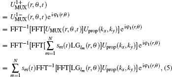
where φ1(r,θ) is the first random phase screen. Here, FFT, FFT−1 are computed in the spatial domain, which have no relationship with the variable sm(t). Hence, sm(t) is picked out from FFT and FFT−1 transformation.

The procedure is repeated until the last random phase screen is reached. Therefore, the multiplexed OAM beams after the turbulent aberration channel are
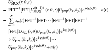
where n is the total number of random thin sheet phase screens, n(t) is the channel AWGN noise, is defined as the deformed OAM mode,

Here, represents the state after the pure OAM mode LGlm(r,θ) transmitting through all n random thin sheet phase screens, where the space distance between the successive random phase screens is ΔZ. It is indicated that is the deformed LGlm(r,θ) spatial mode. There is a correlation between any two of them; i.e., and , ij, i, j ∈ [1,N] are not orthogonal.

Equation (6) shows that the output of the OAM-multiplexed communication link disturbed by AT can be considered to be a communication system with each user’s information sm(t) modulated by a corresponding deformed OAM mode . Consequently, the crosstalk caused by AT in the turbulent aberration channel is now moved to the modulation procedure with a deformed OAM mode at the transmitter. Of course, the crosstalk is produced among the different OAM spatial channel modes because the deformed OAM modes expressed in Eq. (7) are not orthogonal to each other either in the superposition state.

2.2. The turbulence mitigation using de-correlating MUD detection

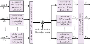
It is shown that equation (6) is a typical formula of received signal in a multiple access channel (MAC) system, where , m ∈ 1,…,N are functions similar to direct spread sequences in the MAC system, and n(t) is a channel AWGN noise. The inner product of any two deformed OAM spatial modes (,) is similar to the correlation between two users in the MAC system. Accordingly, MUD method could be used to solve the above problem. Figure 2 is a schematic diagram of the proposed turbulence mitigation scheme based on MUD. In the scheme, the received multiplexed OAM beams are first de-multiplexed by each deformed OAM mode matched filter, which is denoted as , k ∈ [1,N],

where is the k-th received OAM mode with topological charge lk. denotes the state when the pure OAM beam LGlk(r,θ) transmits distance nΔZ without AT disturbance (representing by n random phase screens) and AWGN noise, n is the total random phase screens number with ΔZ distance of any neighbouring phase screens.

Fig. 2. The turbulence mitigation scheme based on MUD for the OAM-multiplexed FSO communication link.

Therefore, the received signal for the k-th user yk(t) through deformed OAM mode matched filter can be given as

where is a conjugate of . Crosstalk factor ηkm and nk(t) are defined as

Moreover, by dividing both sides of Eq. (9) with ηkk, the received signal for the k-th user ŷk(t) can be simplified as

where and

From Eq. (12), it is shown that the k-th received signal ŷk(t) contains the k-th user’s useful information sk(t), and the correlation information from other users, where is the normalized crosstalk factor.

For all the users, the received signals are given as
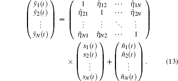
The corresponding matrix formula is

where H is the normalized cross-correlation matrix with the relative crosstalk , and N is the AWGN vector which has elements of

The cross-correlation matrix H shown in Eq. (14) is determined by the normalized crosstalk factor , where ηkm is the inner product between the output of the m-th OAM mode which passed through the atmosphere turbulence channel and the OAM mode transmitting distance z without turbulence. The details for and are described by Eqs. (7) and (8).

If H in Eq. (14) is invertible, the solution for S can be obtained by multiplying each side of the Eq. (14) by H−1,

This is called de-correlating MUD method. It is shown that the de-correlating MUD method can effectively cancel the interference between users. Importantly, the de-correlating MUD method makes the interference caused by AT become a useful component to obtain the users’ information. As displayed in Eq. (15), the received users’ information is only interfered by additive white Gaussian noise.

Of course, the matrix H is not always invertible. Furthermore, the computational complexity is normally high, even if the invertibility of H is existed. The other MUD solution, such as blind adaptive detection algorithm,[37] can be used to solve the problem in Eq. (14). Furthermore, the cross-correlation matrix H should be altered during the multi-user detection method used. Hence, it is suitable for atmospheric turbulence that varies slowly.

3. Numerical simulations

In this section, we discuss the effect of the proposed turbulence mitigation scheme by numerical simulations. We use 10 random phase screens to approximate AT disturbance. The transmitting distance z is 1000 m, and the space distance between the successive random phase screens is ΔZ = 100 m. The inner scale size of phase screen is l0 = 1 mm, the outer scale size of phase screen is L0 = 50 m. The size of the phase screen is 128 × 128 with grid spacing Δx = 2 mm. The structure constant of the index of refraction , representing the different turbulence strength, is set from 1 × 10⁻¹⁵ m−2/3 to 1 × 10⁻¹³ m−2/3. Four users are used in the multiplexing system. Each user carries an OOK signal using the binary bits stream. The binary bits stream is represented by an independent and identically distributed (i. i. d.) binary sequence with equal probability p0 = p1 = 1/2. The iteration number of the binary bits stream is 10000. The parameters for the LG mode are as follows. The radial number of Laguerre polynomial is p = 0, the radius of the zero-order Gaussian beam at the waist is w0 = 0.035 m, and the wavelength is λ = 1550 nm.

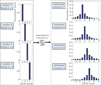
Figure 3 shows the crosstalk caused by AT in the superposition OAM mode beam for the transmitted OAM spatial modes lm ∈ {+1,+2,+3,+4} when is 1 × 10⁻¹⁴m−2/3, the received OAM modes are LG modes with lk ∈ {−3,−2,−1,0,+1,+2,+3,+4,+5,+6,+7,+8}. It is shown that the superposition OAM mode beam is distorted when it is transmitted through AT. Using the transmitted OAM mode lm = +1 as an example, the normalized power of received OAM mode lk = +1 is 0.42, the other power is moved to OAM modes lk = {−3,−2,−1,0,+2,+3,+4,+5,+6,+7,+8}. Their normalized powers are 0.0234, 0.0406, 0.0721, 0.129, 0.141, 0.072, 0.039, 0.021, 0.011, 0.008, and 0.005, respectively. It is shown that AT induces heavily crosstalk to the OAM spatial modes, which results in a quality degradation of the OAM-multiplexed communication link.

Fig. 3. The crosstalk caused by AT on the OAM-multiplexed FSO link with the transmitted OAM modes lm ∈ {+1,+2,+3,+4} when is 1 × 10⁻¹⁴ m−2/3, the received OAM modes are LG modes with lk ∈ {−3,−2,−1,0,+1,+2,+3,+4,+5,+6,+7,+8}.

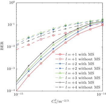
Figure 4 shows the BER performance of OAM-multiplexed communication link with and without MUD mitigation scheme against the strength of AT , where SNR for AWGN noise is set to 20 dB. Figure 4 chooses transmitted and received OAM modes as LG modes with lm,lk ∈ {+1,+2,+3,+4}. The results show that the BER performance of the OAM-multiplexed FSO link decreases as increases. In addition, the BER performance is improved greatly by using the proposed scheme. When is 1 × 10⁻¹⁵ m−2/3, the BER performance of the proposed scheme is 1 × 10⁻⁴, 2 × 10⁻⁴, 3 × 10⁻⁴, 2.5 × 10⁻⁴, respectively, which is a 1–2 fold increase in comparison with those results without the MUD mitigation scheme.

Fig. 4. The BER performance of OAM-multiplexed FSO link with and without MUD mitigation scheme against when the transmitted four OAM modes are lm ∈ {+1,+2,+3,+4}, where SNR for AWGN noise is set to 20 dB. MS represents the proposed MUD mitigation scheme.

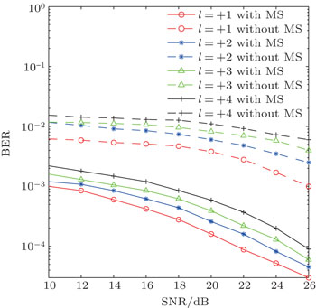
Figure 5 shows the BER performance of OAM-multiplexed FSO link with and without the proposed MUD mitigation scheme against SNR when the transmitted and received OAM modes are lm, lk ∈ {+1,+2,+3,+4}, and is 1 × 10⁻¹⁵ m−2/3. The results show that the BER performance of the OAM-multiplexed FSO link decreases as the SNR increases. When SNR is 26 dB, the BER performance with MUD are all close to 10−5 for the four OAM modes lm ∈ {+1,+2,+3,+4}, which is a 2–3 fold increase in comparison with those results without the MUD mitigation scheme.

Fig. 5. The BER performance of OAM-multiplexed FSO link with and without the proposed MUD mitigation scheme against SNR when the transmitted four OAM modes are lm ∈ {+1,+2,+3,+4}, and is 1 × 10⁻¹⁵ m−2/3. MS represents the proposed MUD mitigation scheme.

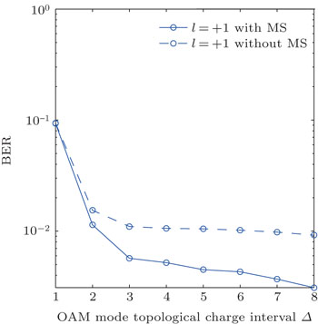
In order to demonstrate the mitigation effect of the proposed scheme on the crosstalk, figure 6 shows the BER performance of a two OAM-multiplexed FSO link with one transmitted OAM channel mode is lm1 = +1 and the other is lm2 = +1+Δ, against OAM topological charge interval Δ, when is 1 × 10⁻¹⁴ m−2/3 and SNR is 20 dB. The results show that the larger topological charge interval Δ is, the better BER performance the OAM-multiplexed FSO link has. Simultaneously, the two OAM-multiplexed FSO link with the proposed MUD mitigation scheme has a better BER performance in comparison with those without the MUD mitigation scheme. The reason for this is that the OAM-multiplexed FSO link has a less crosstalk when the modes in the link with a larger topological charge interval and the proposed MUD mitigation scheme has a better performance on the less crosstalk. When the topological charge interval Δ is 1, the BER performance with the proposed scheme is the same as the BER performance without the proposed scheme. As the OAM mode topological charge interval increases, the BER performance of lm = +1 mode with the proposed scheme becomes better. When Δ is 8, the BER performance with the proposed scheme can be an almost 1-fold increase on that without the MUD mitigation scheme.

Fig. 6. The BER performance of a two OAM-multiplexed FSO link with the two OAM-multiplexed modes being lm1 = +1 and lm2 = +1+Δ, against OAM topological charge interval Δ, when is 1 × 10⁻¹⁴ m−2/3 and SNR is 20 dB. MS represents the proposed MUD mitigation scheme.
4. Conclusion

In this paper, we have proposed a MUD idea turbulence mitigation scheme for the OAM-multiplexed FSO communication link. First, we have presented a MUD equivalent communication model for the OAM-multiplexed FSO communication link disturbed by AT. In the equivalent model, the crosstalk caused by AT is moved from the channel to the transmitter and used as the correlations between the users. Then, we have given an MUD solution for the equivalent model to enhance the AT tolerance of the OAM-multiplexed FSO communication link. In the scheme, the crosstalk caused by AT is not regarded as noise but is regarded as a useful component to obtain the users’ information. The results have shown that the proposed mitigation scheme can effectively improve the AT tolerance of the OAM-multiplexed FSO communication link. For the four OAM-multiplexed FSO communication links with the transmitted OAM spatial modes lm = {+1,+2,+3,+4}, the BER performance with the proposed scheme is close to 10−5, which is a 2–3 fold increase in comparison with those results without the MUD mitigation scheme. Here, is 1 × 10⁻¹⁵ and channel SNR is 26 dB. Moreover, the OAM-multiplexed FSO link with a larger OAM mode topological charge interval in the proposed MUD mitigation scheme has a better BER performance.

Reference
1Allen LPadgett M JBabiker M 1999 Prog. Optics 39 291
2Franke-Arnold SAllen LPadgett M 2008 Laser Photon. Rev. 2 299
3Ding P FPu J X 2014 Opt. Exp. 22 1350
4Wang JYang J YFazal I MAhmed NYan YHuang HRen Y XYue YDolinar STur MWillner A E 2012 Nature Photon. 6 488
5Fontaine N KDoerr C RBuhl L2012Proceedings of the Optical Fiber Communication ConferenceMarch 4–8, 2012Los Angeles, United Statesp. OTu1I.2
6Yan YYue YHuang HYang J YChitgarha M RAhmed NTur MDolinar S JWillner A E 2012 Opt. Lett. 37 3645
7Bozinovic NYue YRen Y XTur MKristensen PHuang HWillner A ERamachandran S 2013 Science 340 1545
8Yue YBozinovic NRen Y XHuang HTur MKristensen PRamachandran SWillner A E2013Proceedings of the Optical Fiber Communication ConferenceMarch 17–21, 2013Anaheim, United Statesp. OTh4G.2
9Huang HXie G DYan YAhmed NRen Y XYue YRogawski DWillner M JErkmen B IBirnbaum K MDolinar S JLavery M P JPadgett M JTur MWillner A E 2014 Opt. Lett. 39 197
10Fang YYu J JChi NZhang J WXiao J N 2015 IEEE Photon. 7 7900506
11Ramachandran SGregg PKristensen PGolowich S E 2015 Opt. Exp. 23 3721
12Ren Y XWang ZLiao P CLi LXie G DHuang HZhao ZYan YAhmed NLavery M P JAshrai NAshrafi SLinquist R DTur MDjordjevic I BNeifeld M AWillner A E2015Proceedings of the Optical Fiber Communication ConferenceMarch 22–26, 2015Los Angeles, United Statesp. M2F.1
13Li LXie G DRen Y XAhmed NHuang HZhao ZLiao P CLavery M P JYan YBao C JWang ZAshrafi NAshrafi STur MWillner A E2015Proceedings of the Optical Fiber Communication ConferenceMarch 22–26, 2015Los Angeles, United Statesp. M2F.6
14Wang LZhao S MGong L YCheng W W 2015 Chin. Phys. 24 120307
15Li Y QWu Z SZhang Y YWang M J 2014 Chin. Phys. 23 074202
16Qian X MZhu W YRao R Z 2015 Chin. Phys. 24 044201
17Boufalah FDalil-Essakali LNebdi HBelafhal A 2016 Chin. Phys. 25 064208
18Pors B JMonken C HEliel E RWoerdman J P 2011 Opt. Exp. 19 6671
19Rodenburg BLavery M P JMalik MO’Sullivan M NMirhosseini MRobertson D JPadgett MBoyd R W 2012 Opt. Lett. 37 3735
20Zhao S MYang HLi Y QCao FSheng Y BCheng W WGong L Y 2013 Opt. Commun. 294 223
21Chandrasekaran NShapiro J H 2014 IEEE J. Lightw. Technol. 32 1075
22Anguita J ANeifeld M AVasic B V 2008 Appl. Opt. 47 2414
23Ren Y XHuang HXie G DAhmed NYan YErkmen B IChandrasekaran NLavery M P JSteinhoff N KTur MDolinar SNeifeld MPadgett M JBoyd R WShapiro J HWillner A E 2013 Opt. Lett. 38 4062
24Ren Y XXie G DHuang HBao C JYan YAhmed NLavery M P JErkmen B IDolinar STur MNeifeld M APadgett M JBoyd R WShapiro J HWillner A E 2014 Opt. Lett. 39 2845
25Ren Y XXie G DHuang HAhmed NYan YLi LBao C JLavery M P JTur MNeifeld M ABoyd R WShapiro J HWillner A E 2014 Optica 1 376
26Xie G DRen Y XHuang HLavery M P JAhmed NYan YBao C JLi LZhao ZCao Y WWillner MTur MDolinar S JBoyd R WShapiro J HWillner A E 2015 Opt. Lett. 40 1197
27Djordjevic I BAnguita J AVasic B 2012 IEEE J. Lightw. Technol. 30 2846
28Zhao S MWang LZou LGong L YCheng W WZheng B YChen H W 2016 Opt. Commun. 376 92
29Xu Z DGui C CLi S HZhou J YWang J2014Proceedings of the Advanced Photonics Communication ConferenceJuly 13–17, 2014San Diego, United Statesp. JT3A.1
30Kohno RHatori MImai H1983Electr. Commun. JPN6620
31Verdú S1998Multiuser DetectionNew YorkCambridge University Press234242234–42
32Duel-Hallen AHoltzman JZvonar Z 1995 IEEE Pers. Commun. 2 46
33Ping L 2005 IEEE Commun. Mag. 43 S19
34Schneider K S 1979 IEEE Trans Aerosp. Electron. Syst. AES-15 181
35Duel-Hallen A 1993 IEEE Trans. Commun. 41 285
36Poor H VVerdú S 1997 IEEE Trans. Inf. Theory 43 858
37Honig MMadhow UVerdú S 1995 IEEE Trans. Inf. Theory 41 944
38Wang X DPoor H V 1999 IEEE Trans. Commun. 47 1046
39Aazhang BParis B POrsak G C 1992 IEEE Trans. Commun. 40 1212
40Allen LBeijersbergen M WSpreeuw R J CWoerdman J P 1992 Phys. Rev. 45 8185
41Sueda KMiyaji GMiyanaga NNakatsuka M 2004 Opt. Exp. 12 3548
42Ding P FPu J X2011Acta Phys. Sin.60094204(in Chinese)
43Strasburg J DHarper W W2004Proceedings of SPIE, Laser Systems Technology IIApril 12, 2004Orlando, United States93