A proposal for the generation of optical frequency comb in temperature insensitive microcavity
Lei Xun, Bian Dandan, Chen Shaowu†,
State Key Laboratory on Integrated Optoelectronics, Institute of Semiconductors, Chinese Academy of Sciences, Beijing 100083, China


† Corresponding author. E-mail: swchen@semi.ac.cn

Project supported by the National Natural Science Foundation of China (Grant Nos. 61435002, 61527823, and 61321063).

Abstract
Abstract

We numerically simulate the generation of an optical frequency comb (OFC) in a microring based on the traditional Si3N4 strip waveguide and a temperature compensated slot waveguide. The results show that OFCs are susceptible to temperature with strip waveguide while they can keep stable when temperature changes 10 K in either low-Q (105) or high-Q (106) microcavity with the well-designed slot waveguide, which has great superiority in practical applications where the temperature drift of the cavity due to the intense pump or surrounding change is unavoidable.

1. Introduction

Optical frequency combs (OFCs)[1,2] have become a powerful tool for high precision spectroscopy and are thereby used for various applications such as sensitive gas sensing,[3] molecular fingerprinting,[4] optical clocks,[5] and attosecond physics.[6] A monolithic frequency comb generator has been demonstrated for the first time in Ref. [7]. This approach is based on continuously pumped fused silica micro resonators on a chip, in which frequency combs are generated via parametric frequency conversion through four-wave mixing.[8] An important aspect of OFC in metrology is the stabilization of the comb repetition rate (fr) and carrier envelope offset frequency (fCEO).[8]

Due to the high pump power coupled into the resonator, the optical modes experience a significant thermal frequency shift as a result of the light absorption in the micro resonator. Usually the pump light is tuned into a resonance from high to low frequencies and the heating of the cavity is balanced by convective and conductive cooling, which allows for “thermal locking” [915] of the micro resonator mode to the pump laser and has been successfully used for self-stability of microcavities. Self-stability can compensate for various types of noise, but it cannot compensate a continuous slow drift, such as the case that the room temperature changes a few degrees.[10] What is more, it will be an unstable thermal equilibrium when the pump wavelength locates at the long wavelength side of the resonance wavelength, which is necessary in the generation of OFC on certain conditions. So we need some new approaches to stabilize the OFC. By using electronic feedback on both laser frequency and laser power, a micro resonator Kerr comb has been fully frequency stabilized with a relative accuracy of 10−16.[12] However, this frequency stabilizing method is very complicated and expensive, which hinders some applications of the on-chip OFC such as multi-wavelength WDM light sources where the frequency stabilization is necessary but not as severe as those needed for high precise spectrum metrology. Therefore, a passive temperature compensation method is of great practical importance and highly desirable. In this work we numerically simulate the stability of OFC generated in a microring resonator based on a temperature-compensated silicon nitride slot waveguide.

2. Simulation results and discussion

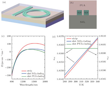
We have recently designed a polyurethane acrylate (PUA)-cladding silicon nitride slotted waveguide,[16] which is shown in Fig. 1(b). Figure 1(a) shows the schematic structure of the all-pass microring resonator constructed by the PUA-cladding slotted waveguide on SiO2 substrate which will be used as the core component of the OFC generator. The device is upper-cladded with lower refractive index material PUA, which has the thermo–optic coefficient of the opposite sign compared to that of the silicon nitride. Figure 1(c) shows a flat second-order dispersion curve covering a broad frequency band obtained in this waveguide, which is favorable to support broadband combs.[1719] Figure 1(d) shows the effective refractive index of different waveguides as a function of temperature. We can get an almost completely athermal design of a PUA-cladding slotted silicon nitride waveguide with proper slot width and silicon nitride width. The thermo–optic coefficient (∂neff/∂T) is 3.8 × 10⁻⁵ K−1 for silicon nitride strip waveguide and 1.3 × 10⁻⁸ K−1 for the temperature-compensated silicon nitride slotted waveguide, corresponding to a resonant wavelength thermo-shifting rate of 32 pm/K and 0.01 pm/K near 1550 nm respectively when the radius of the microring is 100 μm. By comparing the two coefficients, the temperature-compensated silicon nitride slotted waveguide is much more temperature insensitive than the strip waveguide. In the following, we will investigate the influence of temperature change on the generation of OFC by numerical simulation.

Fig. 1. (a) Schematic of an all-pass microring resonator constructed by PUA-cladding silicon nitride slotted waveguide. (b) The corresponding waveguide cross section. (c) Second-order dispersion versus wavelength for different waveguide. (d) Effective refractive index of the waveguide versus temperature. The red, blue, and green curves represent strip waveguide, slot waveguide with SiO2 cladding, and slot waveguide with PUA cladding, respectively.

To numerically demonstrate the influence of the temperature change on OFC generation in different waveguides, we simulate the comb generation process using the Lugiato–Lefever equation[20,21]

where the field envelope has been rescaled so that ψ = (2g0/ω0)1/2A* and the time has been rescaled so that τ = ω0t/2. The dimensionless parameters of this normalized equation are the frequency detuning α = −2σ/ω0, the dispersion β = − 2ζ2/ω0, and the external pump F = (2g0/ω0)1/2f*.

Turing rolls and (bright) cavity solitons[21] are two important forms of OFC, which both are taken into account in our simulation. The initial cold cavity temperature is set to 300 K, and the dispersion of the strip waveguide and the slotted waveguide is 105.6 ps/(nm·km) and 28.7 ps/(nm·km), respectively. The quality factor is assumed to be 100000, which corresponds to a waveguide loss of ∼2 dB/cm.[22]

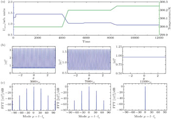
We set the initial detuning as −0.02 nm and OFC is stimulated from a cold cavity of 300 K. We then simulate the evolution of the OFC while the temperature changes slowly, as shown in Fig. 2(a). Figures 2(b) and 2(c) show the time domain and frequency domain status of the Turing rolls, and the spacing between the comb lines is 33 FSR (corresponding to the number of the “rolls” in time domain) at 3000τph and 34 FSR at 7000τph. Even worse, when the temperature is further raised, such as at 11000τph, the OFC will be substantially diminished, even to be vanished. Besides, the total intracavity energy[23] (denoted as UIntra) at different time is also different. So we can conclude that the OFC is greatly influenced by the temperature change in traditional Si3N4 microcavity, even though the temperature shifting is merely a few tenths of one degree.

Fig. 2. (a) The temperature of the micro cavity (green curve) and the average round trip energy values of the cavity (blue). The horizontal axis is scaled in units of photon lifetime τph. The time domain (b) and the corresponding frequency domain status (c) of the OFC at 3000τph, 7000τph, and 11000τph, respectively. We denote the eigennumber of the pumped mode as l0.

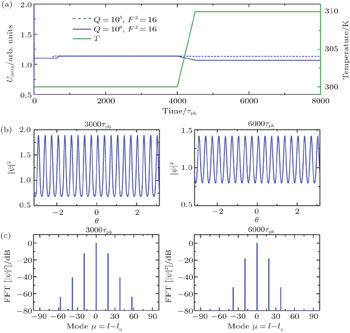
The fluctuation of temperature may cause the change of frequency detuning, and then results in the movement of OFC in the parameter space. The change of OFC mainly depends on its initial position in the parameter space and the variation of frequency detuning. So OFC is more susceptible to temperature in high Q microcavity due to its narrow mode bandwidth. To show the stability of OFC generated in the temperature compensated slot waveguide, we also simulate the evolution of OFC in high Q microcavity. Comparing to the simulation in Fig. 2, the initial normalized detuning and the cavity temperature keep the same but the temperature raises 10 K in the simulation of Fig. 3. The dynamic evolution of OFC is shown in Fig. 3.

Fig. 3. (a) The temperature of the micro cavity (green curve) and the average round trip energy values of the cavity (blue). The time domain (b) and the corresponding frequency domain status (c) at 3000τph and 6000τph when F2 = 16 in microcavities with Q = 106.

The blue dotted curve in Fig. 3 represents the intracavity energy of Turing rolls when Q = 105 and it is almost invariable when temperature changes a lot. The blue solid curve represents the case of Q = 106. Figures 3(b) and 3(c) represent the corresponding time domain and frequency domain status. The spacing between the comb lines keeps 19 FSR, but the power in time domain suffers a small decrease when temperature raises 10 K.

Comparing Figs. 2 and 3, we can make a conclusion that the microring based on temperature compensated slot waveguide is much more temperature insensitive in the dynamic evolution of Turing rolls. The Turing rolls is almost unchanged in the slot waveguide when the temperature rises for 10 K in the low-Q microcavity, while it varies obviously in the strip waveguide though the temperature raises only 0.25 K. What is more, Turing rolls in the slot waveguide still keep an acceptable stability in the high-Q cavity.

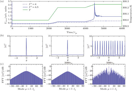
To show the influence of temperature on the evolution of soliton, we set the initial detuning as 0.03 nm and the process of simulation is similar to the above. First, we simulate the case for the traditional Si3N4 microcavity. The peak power of the soliton decreases while its duration increases as the temperature slowly drifts from 300 K to 300.25 K when the pump power is F2 = 4. But the evolution of soliton is quite different when F2 = 4.5. After a drastic oscillation, the single soliton splits into multi-solitons in time-domain and the envelope of the comb lines becomes irregular in the frequency domain when the temperature rises from 300.2 K to 300.25 K, as shown in Fig. 4(a).

Fig. 4. (a) The temperature of the micro cavity (green curve) and the average round trip energy values of the cavity (blue). The blue solid line and the dotted line represent the different paths when the pump power is different. The time domain (b) and the corresponding frequency domain status (c) of the OFC at 1000τph, 3000τph, and 5000τph when the pump power is F2 = 4.5.

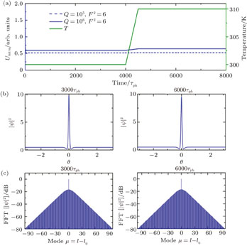
Then, we deal with the case for the temperature compensated slot waveguide under the same initial detuning condition. The result of Fig. 5 indicates that the cavity soliton varies little in microring based on the temperature compensated slot waveguide when the temperature rises for 10 K. It shows that the microcavity based on the temperature compensated slot waveguide has a pretty good thermal stability compared with that based on the traditional Si3N4 microcavity.

Fig. 5. (a) The temperature of the micro cavity (green curve) and the average round trip energy values of the cavity (blue). The time domain (b) and the corresponding frequency domain status (c) at 2000τph and 6000τph when F2 = 6, Q = 106 .

The small dispersion of slot waveguide is not beneficial to getting natively mode-spaced (NMS) combs,[24] but its flattened anomalous dispersion profile allows for the generation of a broadband frequency comb. The most important is that OFC is nearly not influenced by the fluctuation of temperature in this waveguide. These characteristics may make the microcavity based on the slot waveguide an ideal device for the generation of OFC.

3. Conclusion

We simulate the dynamic evolution of the Turing rolls and cavity soliton while the temperature changes slowly, which mimic the actual process. The results demonstrate that the microcavity based on the temperature compensated slot waveguide is much more temperature insensitive than the traditional strip waveguide. OFC stimulated from a microcavity based on the temperature compensated slot waveguide can keep stable when temperature raises 10 K. So the slot waveguide is of great practical importance in the application of OFC or other microcavity based optical devices.

Reference
1Holzwarth RUdem THänsch T WKnight J CWadsworth W JRussell P S J 2000 Phys. Rev. Lett. 85 2264
2Diddams S AJones D JYe JCundiff S THall J LRanka J KWindeler R SHolzwarth RUdem THänsch T W 2000 Phys. Rev. Lett. 84 5102
3Thorpe M JMoll K DJones R JSafdi BYe J 2006 Science 311 1595
4Diddams S AHollberg LMbele V 2007 Nature 445 627
5Diddams S AUdem TBergquist J CCurtis E ADrullinger R EHollberg LItano W MLee W DOates C WVogel K RWineland D J 2001 Science 293 825
6Goulielmakis EYakovlev V SCavalieri A LUiberacker MPervak VApolonski AKienberger RKleineberg UKrausz F 2007 Science 317 769
7Del'Haye PSchliesser AArcizet OWilken THolzwarth RKippenberg T J 2007 Nature 450 1214
8Kippenberg T JHolzwarth RDiddams S A 2011 Science 332 555
9Del'Haye PHerr TGavartin EGorodetsky M LHolzwarth RKippenberg T J 2011 Phys. Rev. Lett. 107 063901
10Carmon TYang LVahala K J 2004 Opt. Express 12 4742
11Grudinin I SYu NMaleki L 2009 Opt. Lett. 34 878
12Del'Haye PArcizet OSchliesser AHolzwarth RKippenberg T J 2008 Phys. Rev. Lett. 101 053903
13Foster M ALevy J SKuzucu OSaha KLipson MGaeta A L 2011 Opt. Express 19 14233
14Okawachi YSaha KLevy J SWen Y HLipson MGaeta A L 2011 Opt. Lett. 36 3398
15Levy J SGondarenko AFoster M ATurner-Foster A CGaeta A LLipson M 2010 Nat. Photonics 4 37
16Bian DChen SLei XQin GChen Z 2016 Appl. Opt. 55 4827
17Bao CZhang LMatsko AYan YZhao ZXie GAgarwal A MKimerling L CMichel JMaleki LWillner A E 2014 Opt. Lett. 39 6126
18Zhang LBao CSingh VMu JYang CAgarwal A MKimerling L CMichel J 2013 Opt. Lett. 38 5122
19Bao CZhang LYan YHuang HXie GAgarwal AKimerling LMichel JWillner A2014CLEO: Scienceand InnovationsJune 8-13, 2014San Jose, CAp. SM1M. 5
20Coen SErkintalo M 2013 Opt. Lett. 38 1790
21Chembo Y KMenyuk C R 2013 Phys. Rev. 87 053852
22Zhang XLiu TJiang JFeng MLiu K 2014 Opt. Commun. 332 125
23Jaramillo-Villegas J AXue XWang P HLeaird D EWeiner A M 2015 Opt. Express 23 9618
24Herr THartinger KRiemensberger JWang C YGavartin EHolzwarth RGorodetsky M LKippenberg T J 2012 Nat. Photonics 6 480