Theoretical derivation and simulation of a versatile electrostatic trap for cold polar molecules
Li Shengqiang†,
School of New Energy and Electronic Engineering, Yancheng Teachers University, Yancheng 224002, China


† Corresponding author. E-mail: lishengqiang_2007@126.com

Project supported by the National Nature Science Foundation of China (Grant No. 11504318).

Abstract
Abstract

We propose a versatile electrostatic trap scheme using several charged spherical electrodes and a bias electric field. We first give the two-ball scheme and derive the analytical solution of the electric field. In order to make a comparison, we also give the numerical solution calculated by the finite element software (Ansoft Maxwell). Considering the loading of cold polar molecules into the trap, we give the three-ball scheme. We first give the analytical and numerical solutions of the distribution of the electric field. Then we simulate the dynamic process of the loading and trapping cold molecules using the classical Monte Carlo method. We analyze the influence of the velocity of the incident molecular beam and the loading time on the loading efficiency. After that, we give the temperature of the trapped cold molecules. Our study shows that the loading efficiency can reach 82%, and the corresponding temperature of the trapped molecules is about 24.6 mK. At last, we show that the single well divides into two ones by increasing the bias electric field or decreasing the voltages applied to the spherical electrodes.

1. Introduction

Cold molecules play an important role in basic physics and advanced technology. Cold molecules have lots of applications, such as high-resolution spectroscopy[1] and precision measurements,[2] cold collisions and cold chemistry,[35] quantum computing and quantum information processing,[6] and so on. Manipulation of cold polar molecules using the interaction between their electric dipole moments with an inhomogeneous electric field has obtained great achievements in recent years. In 2000, Meijer’s group trapped the ND3 molecules in the weak-field-seeking (WFS) state using an electrostatic well for the first time. After that, they succeed in trapping OH radical[7] and metastable CO molecules[8] using the same setup. In 2005, Rempe group trapped ND3 molecules in a continuously operated electrostatic trap.[9] In 2007, Kleinert et al. confined ultracold polar NaCs molecules using thin-wire electrostatic trap.[10] In 2009, Meijer’s group reported the trapping of carbon monoxide molecules on a chip using direct loading from a supersonic beam.[11] Yin’s group has also made considerable contributions to this area.[1218] In 2013, Wang et al. proposed an electrostatic trap with three-dimensional (3D) optical access using two charged spherical electrodes.[15] Though the optically accessible trap can catch cold polar molecules in the WFS state, it still has some shortcomings. The main drawbacks are as follows. First, the loading efficiency is only 14%. Second, as is demonstrated, double-well trap has lots of important applications in atom and molecule optics.[1922] While in this scheme, only single trap can be formed. Last but not least, the analytical solutions for the distribution of the electric field in the ultimate scheme are not given. Though in 2015, they proposed an improved scheme,[16] the last two shortcomings still need to be overcome.

To solve these problems, we propose a versatile electrostatic trap with open optical access for cold polar molecules in the WFS state using several spherical electrodes and a bias electric field. We not only derive the analytical solution of the electric field, but also give the numerical solution calculated by the finite element software. We demonstrate the feasibility of our trap scheme using classical Monte Carlo simulations. In Section 2, we first give the two-ball scheme. In Section 3, considering the load of the cold polar molecules, we give the three-ball scheme, and give the analytical solution and numerical solution of the electric field. We perform the classical Monte Carlo simulations to better understand the dynamic behavior of cold molecules in the loading and trapping processes. We show that the single well can be divided into two halves by continuously increasing the intensity of the bias electrode field.

2. The two-ball scheme
2.1. Formula derivation

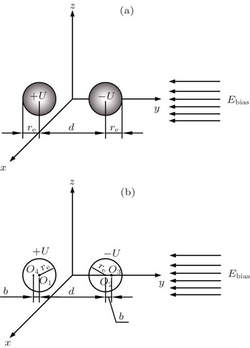
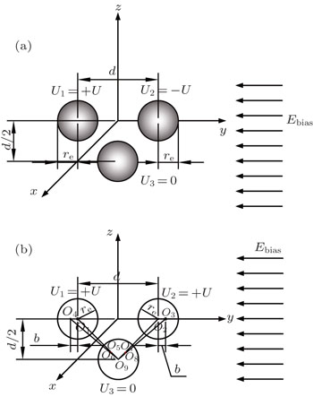
The two-ball scheme is composed of two charged spherical electrodes with a radius of re, as shown in Fig. 1. The distance between the centers of the two spheres is d. The two spherical electrodes are placed along the y axis. The midpoint of the two centers of the spheres is set as the origin of the coordinate system. The voltages applied to the left spherical electrode and the right one are U and –U, respectively. The bias electric field is along the –y axis.

Fig. 1. Schematic diagram of the two-ball scheme (a) and the image charges method (b).

According to the method of image charges, as shown in Fig. 1(b), O1 and O2 are the centers of the two electrodes, respectively, while O3 and O4 are their first-order image points, where b is the distance between O1 and O4 (or O2 and O3). Here, we choose re = 0.004 m, d = 0.016 m, U = 10 kV, and Ebias = −1.8 × 10⁶ V/m.

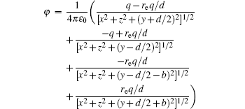
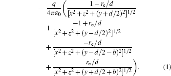
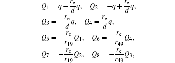
The voltages applied to the electrodes are actually achievable at current stage.[16,2328] The charges Q1, Q2, Q3, Q4 at the points O1, O2, O3, O4 respectively are where q is the charge of the left ball electrode. The coordinates of the points O1, O2, O3, O4 are (0, −d/2, 0), (0, d/2, 0), (0, d/2 + b, 0), and (0, −d/2 − b, 0), respectively. According to the Poisson equation and image charge method,[29] we can get the electric potential φ

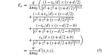
The electrostatic field distribution of our charged balls can be expressed as

Thus,

In order to obtain the relationship between the voltage U and the charge q, we calculate the integral of Ey from d/2 − r to d/2 + r

We assume

With the given values of parameters, we can obtain A ≈ 311.538. Therefore, the relationship between the voltage U and charge q can be given by

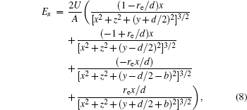
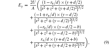
Then the analytical solutions to calculate the electric field in free space can be expressed as

2.2. The comparison between the analytical solutions and numerical solutions

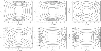
With Eqs. (8)–(11), we calculate the contour distributions of the electric field. In order to make a comparison, we also give the results calculated by the finite element software (Ansoft Maxwell). As the two ball is completely symmetric about x (or z) axis, the electric field shown in Figs. 2(a) and 2(e) (or in Figs. 2(b) and 2(f)) are similar. We can see that our numerical results are consistent with the analytical ones. We can infer that a 3D closed hollow electrostatic field distributions is generated by our two-ball scheme.

Fig. 2. The contour distributions of the trapping field for the X OY plane ((a), (b)), X OZ plane ((c), (d)), and Y OZ plane ((e), (f)) by analytical solutions ((a), (c), and (e)) and numerical solutions ((b), (d), and (f)). Here we use U = 10 kV and Ebias = −1.8 × 10⁶ V/m.
3. The three-ball scheme
3.1. Formula derivation

In this section, we add a spherical electrode to our double-ball scheme in –z axis to realize the efficient loading and trapping of cold polar molecules. The added sphere is the same size as the above mentioned two spheres. The coordinate of the centre of the sphere is (0, 0, –d/2). The voltages applied to the three balls are U1, U2, and U3, respectively. In the process of trapping, U3 = 0, U1 = U, U2 = −U, and Ebias ≠ 0, while in the process of loading, U3 = 0, U1 = U2 = U, and Ebias = 0. Here we use the results of the two-ball scheme to simplify the calculation. We use re = 0.004 m, d = 0.016 m, and U = 10 kV.

The point charges

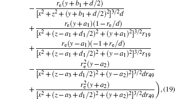
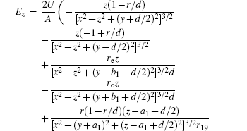
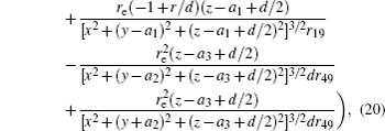
where rij is the distance between the point charge i and the point charge j. Here we set a1 = −1 × 10⁻³ m, and Then using plane geometry knowledge, the coordinates of the charges (Q1, Q2, …, Q9) are (0, −d/2, 0), (0, d/2, 0), (0, d/2 + a1, 0), (0, −d/2 − a1, 0), (0, −a1, −d/2 + a1), (0, −a2, −d/2 + a3), (0, a1, −d/2 + a1), (0, a2, −d/2 + a3), and (0, 0, −d/2), respectively.

Fig. 3. Schematic diagram of the three-ball scheme (a) and the image charges method (b).

According to the Poisson equation and image charge method, we can get the electric potential by
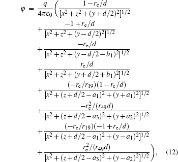
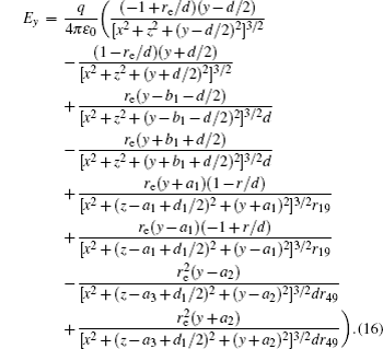
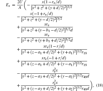
Thus,

In order to obtain the relationship between the voltage U and the charge q, we calculate the integral of Ey from d/2 − r to d/2 + re,

We assume With the given values of parameters, we can obtain A ≈ 311.538. Therefore, the relationship between the voltage U and charge q can be given by

3.2. The comparison between the analytical solutions and numerical solutions

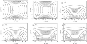
Similar to the two-ball scheme, we compare the contour distributions of the electric field calculated with Eqs. (18)–(21) and by the finite element software (Ansoft Maxwell), shown in Fig. 4. The parameters are re = 0.004 m, d = 0.016 m, U = 10 kV, and Ebias = −1.8 × 10⁶ V/m. We can see that our numerical results are consistent with the analytical ones. We can infer that a 3D closed hollow electrostatic field distributions is generated by our three-ball scheme.

Fig. 4. The contour distributions of the trapping field for the X OY plane ((a), (b)), X OZ plane ((c), (d)), and Y OZ plane ((e), (f)) by analytical solutions ((a), (c), and (e)) and numerical solutions ((b), (d), and (f)). Here we use U = 10 kV and Ebias = −1.8 × 10⁶ V/m.
3.3. The loading and trapping ND3 molecules using the three-ball scheme

We calculate the spatial distribution of the electrostatic field generated by our charged-ball layout and its Stark trapping potential for ND3 molecules, and analyze the effective potential-well depth.

The ND3 molecule in the state |J,K,M〉 = |1, 1, −1〉 has a relatively large electric dipole moment (1.5 Debye). When a ND3 molecule moves in an inhomogeneous electric field, it will experience an electric dipole gradient force, and the corresponding interaction potential will be given respectively by the first-order Stark potential

and the second-order Stark potential

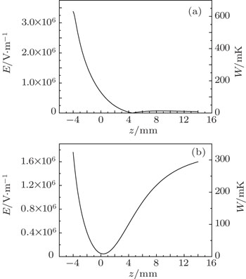
Thus the total Stark trapping potential is Here we use finite element software to calculate the spatial distribution of the electric field of our trap scheme and its Stark trapping potential for ND3 molecules in the state |J,K,M〉 = |1, 1, −1〉, as shown in Fig. 5. The cold molecular beam is loaded along the −z direction. We can see from Fig. 5(a) that when U1 = U2 = 10 kV, U3 = 0, and Ebias = 0, the field distribution in the z direction is asymmetric, that is, the potential barrier (i.e., the right barrier) above the trapping center will be lowered to nearly zero, which can be used to load cold molecular beam into our trap. So when cold molecules move along the −z direction, they will first experience a slowing process resulting from the gradient force of the left electrostatic field until most of them are slowed to 0 m/s, and then be reflected back. When the molecules arrive near the center of the trap, we will fast change the voltage to U1 = −U2 = 10 kV, U3 = 0, and Ebias = −1.8 × 10⁶ V/m, so as to confine cold molecules in our trap.

Fig. 5. The electric field distribution in the z direction including the Stark potential for ND3 molecules in the state |J,K,M〉 = |1, 1, −1〉 during (a) the loading and (b) trapping processes.
3.4. Monte Carlo simulations

In our simulations, the number of simulated molecules is 105. The initial spatial distributions and velocity profiles of incident pulsed ND3 molecular beam are both Gaussian ones, and the transverse (x, y) and longitudinal (z) spatial sizes are 4 and 8 mm, respectively. The center velocity of cold molecular beam in the x and y directions both are 0 m/s, and the corresponding full width at half maximum (FWHM) of the velocity distributions in x, y, and z directions are all 3 m/s. The simulated conditions are actually achievable at current stage.[3032] Here, tload is the time when we change the loading electric field to the trapping one.

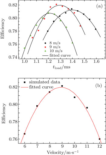
Figure 6(a) shows the relationship between the loading efficiency and the loading time tload for four different initial velocities of the incident molecular beam. We can see that: (i) the loading efficiency of cold molecules is not only relative to the loading time, but also dependent on the initial velocity of incident molecular beam; (ii) for a given initial velocity, there is always an optimal loading time and the maximum loading efficiency. When initial velocities of incident molecular beam are 8 m/s, 9 m/s, and 10 m/s, the optimal loading time are 1.3940 ms, 1.2660 ms, and 1.1998 ms, and the corresponding maximum loading efficiency can reach 81.4%, 82.1%, and 80.8%, respectively. Further, we study the relationship between the maximum loading efficiency of cold molecules and the initial velocity of the incident beam, shown in Fig. 6(b). It can be seen that with the increase of the incident-beam velocity, the maximum loading efficiency will first increase, and then decrease after reaching the maximum value. In particular, when the incident-beam velocity is 9 m/s, the maximum loading efficiency can reach about 82.1%.

Fig. 6. (a) The dependence of loading efficiency on the loading time for different central velocities of the incident molecular beam. (b) The relationship between the loading efficiency and the initial central velocity of the incident molecular beam. The data points are simulated results and the lines are fitted curves.

Figure 7 shows the initial and final velocity distributions of ND3 molecules before loading and after trapping. When the initial velocity of ND3 molecular beam is centered around 0 m/s with a FWHM of ∼ 3 m/s in x or y direction, and centered around 9 m/s with a FWHM of ∼ 3 m/s in the −z direction, the final velocity of ND3 molecular beam after loading and trapping is centered around 0 m/s with a FWHM of 5.74 m/s, 7.29 m/s, 9.16 m/s in the x, y, and z direction, respectively. The corresponding 3D temperature of the trapped cold molecules is about 24.6 mK. This shows that our proposed trap scheme can be used to realize a high-efficient loading (about 82% efficiency) and trapping of cold polar molecules with a temperature of 24.6 mK.

Fig. 7. The velocity distributions of the incident molecular beam before the loading process and the trapped cold molecules, along (a) x direction, (b) y direction, and (c) z direction.
3.5. The transition from single well to double wells

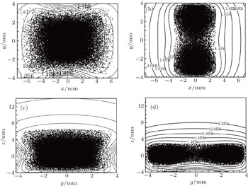
Our layout can easily realize the transition from single well to double wells by changing the values of the bias electric field and the voltages applied to the ball electrodes. When the intensity of bias field increases, the single well splits into two identical halves, shown in Fig. 8. It is clear that when Ebias changes from −1.8 × 10⁶ V/m to −2.8 × 10⁶ V/m, the single well changes into double well.

Fig. 8. The contour distributions of the electrostatic field in the X OY and Y OZ planes during the trapping process as well as the spatial distributions of cold molecules trapped in the well. (a), (c) Single well. U = 10 kV and Ebias = −1.8 × 10⁶ V/m. (b), (d) Double wells. U = 10 kV and Ebias = −2.8 × 10⁶ V/m.

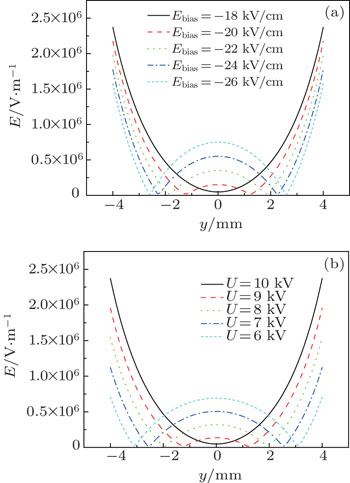
First, we keep U = 10 kV unchanged and analyse how the intensity of electric field affect the formation of double wells, shown in Fig. 9(a). We can see that as the intensity of the bias electric field increases, the single well splits into two halves. The stronger the intensity of the bias electric field is, the farther the distance between the each trap centre is. Similar effect can also be achieved by changing U and keeping the bias electric field unchanged. Then we keep the Ebias = −18 kV/cm unchanged and analyse how the value of the voltage U affect the formation of double wells, as shown in Fig. 9(b). We can see that as U decreases, the single well splits into two halves. The lower U is, the farther the distance between the each trap centre is.

Fig. 9. The transition from single well to double wells. (a) We keep U = 10 kV unchanged, and change Ebias. (b) We keep Ebias = −18 kV/cm unchanged, and change U.
4. Conclusion

We have proposed a novel scheme for trapping cold WFS molecules by using several charged balls and a bias electric field. We analytically and numerically calculate the spatial distributions of the electrostatic field generated by our charged-ball layout and its Stark trapping potential for ND3 molecules. The Monte Carlo simulations for the loading and trapping processes of cold ND3 molecules are performed to study the dependences of the loading efficiency on both the loading time and the initial velocity of the incident molecular beam. The results show that the loading efficiency of our trapping scheme can reach up to 82% when the initial velocity of the molecular beam is 9 m/s, and the corresponding optimal loading time is 1.2660 ms. We also study the transition from single well to double wells by changing the value of the voltage or the intensity of bias electric field. This is of great importance to the interferometric study of molecular matter waves. With cold molecules trapped in an electrostatic well up to seconds, we can study the lifetimes of the electronic or vibrational excited states.[33,34] Trapped polar molecules also hold promise for use in quantum information systems.[35]

Reference
1ThorpeM JMollK DJonesR JSafdiBYeJ 2006 Science 311 1595
2HudsonJ JSauerB ETarbuttM RHindsE A 2002 Phys. Rev. Lett. 89 023003
3GilijamseJ JHoekstraSvande MeerakkerS Y TGroenenboomG CMeijerG 2006 Science 313 1617
4WillitschSBellM TGingellA DProcterS RSotfleyT P 2008 Phys. Rev. Lett. 100 043203
5OttoRMikoschJTrippelSWeidemullerMWesterR 2008 Phys. Rev. Lett. 101 063201
6DeMilleD 2002 Phys. Rev. Lett. 88 067901
7MeerakkerS Y TSmeetsP H MVanhaeckeNJongmaR TMeijerG 2005 Phys. Rev. Lett. 94 023004
8GilijamseJ JHoekstraSMeekS AMetsalaMMeerakkerS Y TMeijerG 2007 J. Chem. Phys. 127 221102
9RiegerTJunglenTRangwalaS APinkseP W HRempeG 2005 Phys. Rev. Lett. 95 173002
10KleinertJHaimbergerCZabawaP JBigelowN P 2007 Phys. Rev. Lett. 99 143002
11MeekS AConradHMeijerG 2009 Science 324 1699
12MaHZhouBLiaoBYinJ P 2007 Chin. Phys. Lett. 24 1228
13WangQLiS QHouS YXiaYWangH LYinJ P 2014 Chin. Phys. 23 013701
14LiS QXuLXiaYWangH LYinJ P 2014 Chin. Phys. 23 123701
15WangZ XGuZ XXiaYJiXYinJ P 2013 J. Opt. Soc. Am. 30 2348
16WangZ XGuZ XDengL ZYinJ P 2015 Chin. Phys. 24 053701
17LiuJ PHouS YWeiBYinJ P 2015 Acta Phys. Sin. 64 173701 (in Chinese)
18XiaYYinY LJiXYinJ P 2012 Chin. Phys. Lett. 29 053701
19AndrewM RTownsendC GMiesnerH JDurfeeD SKurnD MKetterleW 1997 Science 275 637
20InouyeSGuptaSRosenbandTChikkaturA PGörlitzAGustavsonT LLeanhardtA EPritchardD EKetterleW 2001 Phys. Rev. Lett. 87 080402
21AlbiezMGatiRFöllingJHunsmannSCristianiMOberthalerM K 2005 Phys. Rev. Lett. 95 010402
22BuggleCLéonardJvon KlitzingWWalravenJ T M 2004 Phys. Rev. Lett. 93 173202
23van de MeerakkerS Y TSmeetsP H MVanhaeckeNJongmaR TMeijerG 2005 Phys. Rev. Lett. 94 023004
24DengL ZLiangYGuZ ZHouS YLiS QXiaYYinJ P 2011 Phys. Rev. Lett. 106 140401
25GuZ XGuoC XHouS YLiS QDengL ZYinJ P 2013 Phys. Rev. 87 053401
26SteibG FMollE 2002 J. Phys. D-Appl. Phys. 6 243
27VentoV TBergueiroJCartelliDKreinerA A V A J 2011 Appl. Radiat. Isotopes 69 1649
28WangQHouS YXuLYinJ P 2016 Phys. Chem. Chem. Phys. 18 5432
29HaytW HBuckJ A2001Engineering Electromagnetics6th edn.New YorkMcGraw-Hill
30BethlemH LBerdenGCrompvoetsF M HJongmaR Tvan RoijA J AMeijerG 2000 Nature 406 491
31CrompvoetsF M HJongmaR TBethlemH Lvan RoijA J AMeijerG 2002 Phys. Rev. Lett. 89 093004
32HouS YLiS QDengL ZYinJ P 2013 J. Phys. B-At. Mol. Opt. Phys. 46 045301
33van de MeerakkerS Y TVanhaeckeNvan der LooM P JGroenenboomG CMeijerG 2005 Phys. Rev. Lett. 95 013003
34GilijamseJ JHoekstraSMeekS AMetsalaMvan de MeerakkerS Y TMeijerGGroenenboomG C 2007 J. Chem. Phys. 127 221102
35AndreADeMilleDDoyleJ MLukinM DMaxwellS ERablPSchoelkopfR JZollerP 2006 Nat. Phys. 2 636