Polaron effect on the optical rectification in spherical quantum dots with electric field
Feng Zhen-Yu1, Yan Zu-Wei1, 2, †,
School of Physical Science and Technology, Inner Mongolia University, Hohhot 010021, China
College of Science, Inner Mongolia Agricultural University, Hohhot 010018, China


† Corresponding author. E-mail: zwyan101@126.com

Project supported by the National Natural Science Foundation of China (Grant No. 11364028), the Major Projects of the Natural Science Foundation of Inner Mongolia Autonomous Region, China (Grant No. 2013ZD02), and the Project of “Prairie Excellent” Engineering in Inner Mongolia Autonomous Region, China.

Abstract
Abstract

The polaron effect on the optical rectification in spherical quantum dots with a shallow hydrogenic impurity in the presence of electric field is theoretically investigated by taking into account the interactions of the electrons with both confined and surface optical phonons. Besides, the interaction between impurity and phonons is also considered. Numerical calculations are presented for typical Zn1−xCdxSe/ZnSe material. It is found that the polaronic effect or electric field leads to the redshifted resonant peaks of the optical rectification coefficients. It is also found that the peak values of the optical rectification coefficients with the polaronic effect are larger than without the polaronic effect, especially for smaller Cd concentrations or stronger electric field.

1. Introduction

Nonlinear optical properties in low-dimensional semiconductor nanostructures such as quantum wells, quantum wires, and quantum dots (QDs) have aroused much interest in the past few years.[116] In these systems, QDs can confine charge carriers in all spatial dimensions and their sizes, shapes, and other properties can be controlled experimentally. Furthermore, there exists a strong quantum confinement effect in QDs, which induces a dramatic enhancement in optical nonlinearities compared with bulk materials. This property leads to potential applications in electronic and optoelectronic devices.[1719] Therefore, it is necessary to study the nonlinear optical properties of QDs due to their unique physical properties and their potential applications.

Because the electron–phonon interaction plays an important role in the nonlinear optical properties, the polaron effects on linear and nonlinear optical properties have been widely studied.[2025] In nonlinear optical properties, nonlinear optical rectification (OR) in semiconductor heterostructure and nanostructure is a second-order nonlinear optical effect which is important for investigating their electronic structures. Due to the fact that the polaron effect can induce a very large enhancement effect, a lot of authors have devoted themselves to the issue about the polaron effect on the OR coefficient. For instance, Zhang and Guo[26] investigated the effect of the electron–phonon interaction on the OR in a semi-parabolic quantum well and found that the electron–phonon interaction increases the OR up to a factor of 6–13. Wu et al.[27] investigated the polaron effect on nonlinear OR in asymmetrical Gaussian potential quantum well, and revealed that the OR coefficients are strongly dependent on the confinement potential and the electric field, and greatly enhanced by considering the polaron effect. Xiao et al.[28] investigated the polaron effect on the OR in an asymmetrical semi-exponential quantum well, and they reported that when considering the electron-LO-phonon, the resonant peak of the OR is enhanced, and the blue shifts are also observed. Liu et al.[29,30] studied the polaron effect on the OR in cylindrical quantum dots in the presence of electric and magnetic fields and found that the OR coefficient is greatly enhanced, with the polaron effect taken into account. All relative research results reveal that electron–phonon interaction plays a very important role in nonlinear optical properties.

Due to the difference in the dielectric constant of the material between inside and outside the QDs, besides the confined optical (CO) phonons, there exist surface optical (SO) phonons in the structure, and it depends strongly on the QD shape and electric field.[31] In some investigations, the QD shapes were approximated as various forms: cylinders,[29,30] cones,[32] lens,[33,34] pyramids,[35] ellipses,[36,37] spheres,[3840] and the polaronic effect has been studied in some works. Unfortunately, in most of the research mentioned above the impurity–phonon interaction is either ignored or not discussed. In fact, the contribution from impurity–phonon interaction is very important and generally larger than that from electron–phonon interaction.[41,42] To the best of our knowledge, there are fewer research studies related to the polaron effect on the OR in spherical quantum dots with taking into account both electron–phonon and impurity–phonon interaction. For these reasons, the polaron effect is important to the OR of QDs and should be considered in the relevant work.

In this paper, polaron effect on the OR in a spherical quantum dot in the presence of the electric field is theoretically investigated by using a variational approach, with the electron–phonon and impurity–phonon interactions taken into account, including CO and SO phonon modes. To make it closer to the real situation, the electronic confinement is modeled by a finite potential well. The rest of this paper is organized as follows. In Section 2, the electron–phonon interaction and the nonlinear OR coefficients are described. In Section 3, the numerical results and discussions are performed. Finally, some conclusions are briefly drawn from the present study in Section 4.

2. Model and calculation

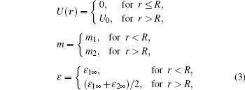
We consider the electron interacting with the optical phonons in a spherical quantum dot comprised of Zn1−xCdxSe/ZnSe with radius R. When the electron is inside (r < R) the QD, it will interact with the internal LO phonons, we call it CO phonons. When the electron is close to the QD boundary (rR), it will interact with the SO phonons. Within the framework of effective mass approximation, the Hamiltonian of the system in the presence of an applied electric field along the z direction is given by

Here, H0 is the Hamiltonian of the electron, which can be written as

with

where m1 (m2) and ε1∞ (ε2∞) are the effective mass and high-frequency dielectric constant in dot (barrier) material respectively, F is the strength of the electric field along the z direction, U(r) is the confinement potential of the spherical QD, es = e/(4πε0)−1/2, and e is absolute value of the electron charge, and ε0 is the vacuum permittivity, θ is the angle between the electronic position vector r and the electric field direction. The second and third term in Eq. (1) representing the classical Hamilton functions of CO and SO phonons can be written respectively as follows:

where ωCO and ωSO,l are the eigenfrequencies of CO and SO phonons respectively. and in Eq. (1) are the Hamiltonian of both electron and impurity interaction with CO and SO phonons, which can be expressed as[43,44]

where

with

and

with

where Yl,m is the spherical harmonic, jl and nl are the l-th order spherical Bessel and Neumann functions respectively, kln = μln/R, μln is the n-th root of jl, ε1∞ (ε2∞) and ε10(ε20) are the high-frequency and static dielectric constants in dot (barrier) material respectively. The index n = 1, 2, …; l = 0, 1, 2,…; m = 0, ±1, ±2, …, ±l for the CO phonons, and l = 1, 2, …; m = 0, ±1, ±2, …, ±l for the SO phonons. In Eqs. (6) and (7), r and r0 are the positions of electron and impurity respectively. In this paper, we assume that the impurity is in the center (the center of the sphere is taken as the origin), i.e., r0 = 0.

Firstly, it is necessary to eliminate the contribution of the impurity–phonon interactions to the total electron energy. It can be obtained by using a first unitary transformation to displace the equilibrium position of the ions as follows:

Here CO and SO represent the CO and SO phonons respectively. The index s is given by n = 1, 2, …; l = 0, 1, 2, …; m = 0, ±1, ±2, …, ±l for the CO phonons, and l = 1, 2,…; m = 0, ±1, ±2, …, ±l for the SO phonons.

Subsequently, the Hamiltonian can be transformed into the following form:

where

and

The nonphysical divergent term arising from the use of the point-charge model has been dropped for convenience, the effect of the above displacement on the lattice polarization leads to the following electron-impurity “exchange” interaction:

The effect of the electron–phonon interaction is to displace further the equilibrium positions of the ions within the adiabatic approximation. This can be obtained by the following unitary transformation:

The parameters fjs are variational functions, which will be determined by minimizing the expectation value of the bound polaron energy. The total wave function of the system can be achieved by the product of the electronic part |φ(r)〉 and the phonon part U′|0〉[45]

with

where N is the normalization constant; λ1 (λ2) and η1 (η2) are the variational parameters for the ground (excited) state, and indicate the degree of spatial correlation between the electron and impurity and the influence of the electric field, respectively; E10 is the energy of the ground state achieved by the transcendental equation:

After some calculations, the expectation value of the system Hamiltonian in the phonon–vacuum state is given by

Then, the minimization of the expectation energy value can be written as

with respect to the variational parameters fjs, which is given by the following expressions:

Finally, inserting Eqs. (25) and (27) into Eq. (26), and the expectation energy E dependent on the variational parameters can be obtained in the form of

In this expression, the first term on the right-hand side indicates the energy of the impurity state, the second term describes the interactions of the electron with both CO and SO phonons, and the last term describes the electron–impurity “exchange” interaction caused by the impurity–phonon interaction.

The analytical expression for the nonlinear optical rectification coefficient can be obtained by a density matrix approach and an iterative procedure[46,47]

where q is the absolute value of the electron charge, σ denotes the electron density in the system, Γi (i = 1,2) is the phenomenological relaxation rate, Γ1 = 1/T1, and Γ2 = 1/T2, with T1 and T2 being the longitudinal and the transverse relaxation times, respectively, M12 = 〈φ1 |z| φ2〉 is the dipole matrix element, δ12 = |〈φ2 |z| φ2〉 − 〈φ1 |z| φ1〉 |, ħω12 = E2E1 is the energy difference between two different electronic states, and ω is the incident photon frequency.

The maximum value of for ω12 = ω is given by

3. Results and discussion

In this section, we will discuss the OR coefficients in a spherical quantum dot with the electric field in the presence of the electron–phonon and impurity–phonon interactions. The parameters used in our calculations are as follows:[4850] σ = 5.0 × 1024 m−3, nr = 2.4, T1 = 1 ps, T2 = 0.1 ps; m1 = 0.13m0, ε10 = 9.3, ε1∞ = 6.1 for CdSe; m1 = 0.171m0, ε10 = 8.33, ε1∞ = 5.9, εd = 2.25 for ZnSe, where m0 is the bare electron mass. The parameters for Zn1−xCdxSe are obtained by linear interpolation from the corresponding values for ZnSe and CdSe. The value of the conduction band offset U0 is assumed to be 80% of bandgap mismatch.[43]

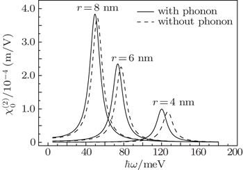
In Fig. 1, we demonstrate the behaviors of OR coefficient in the cases with and without phonon, each as a function of photon energy ħω for different QD radii with F = 5.0 MV/m and x = 0.3. From the figure, it can be clearly seen that the polaronic effect gives rise to the redshifts of the positions of the resonant peaks of the OR coefficients, especially for the smaller QD radius. We find that the redshifts for the OR coefficient are 6.5 meV, 3.5 meV, 2.5 meV for R = 4 nm, 6 nm, and 8 nm, respectively. Besides, a very notable feature of this figure is that when we take into account the polaronic effect, the peak values of the OR coefficient are enhanced. The reason for this feature is that the polaronic effect makes the wave function of an electron spread to wider space, which leads to the fact that the overlap of the wave functions is enhanced.

Fig. 1. Variations of OR coefficient with photon energy ħω with and without phonon for different QD radii with F = 5.0 MV/m and x = 0.3.

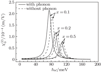
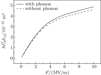
Figure 2 shows the OR coefficients with and without phonon each as a function of photon energy ħω for different Cd concentrations with F = 2.0 MV/m, and R = 5 nm. It can also be seen that the polaronic effect leads to the redshifted resonant peaks of the OR coefficients. We find that the redshifts for the OR coefficient are 7.0 meV, 5.5 meV, and 3.5 meV for x = 0.1, 0.2, and 0.5, respectively. Moreover, from the figure, we can obviously observe that the peak values of with the polaronic effect are larger than without the polaronic effect, especially for the smaller Cd concentrations. Furthermore, it is found that the peak values of decrease with increasing Cd concentration. In order to explain the feature, we show the relationship between the geometrical factor and the Cd concentration x with F = 2.0 MV/m and R = 5 nm in Fig. 3. We know that the resonant peak of is determined by the geometrical factor . From the figure, it is obviously seen that the geometrical factor decreases with x increasing. In addition, the geometrical factor difference between the two cases gradually becomes small with increasing Cd concentration. These results are useful for understanding the results in Fig. 2. Finally, it should be pointed out that from Fig. 2, whether the polaronic effect is considered or not, the peak value of suffers a blue-shift with increasing Cd concentration. The reason for the feature is that with increasing Cd concentration, the confinement potential strengthens, and as a result, the quantum-confinement of the electron is enhanced. Therefore, the energy intervals are much wider, which leads to the fact that the positions of peaks appear on the higher-energy side.

Fig. 2. Plots of OR coefficients versus photon energy ħω with and without phonon for different Cd concentrations with F = 2.0 MV/m and R = 5 nm.
Fig. 3. Variations of geometrical factor with Cd concentration x with and without phonon for F = 2.0 MV/m and R = 5 nm.

Figure 4 shows variations of the OR coefficient with photon energy ħω with and without phonon for different electric fields with R = 5 nm, and x = 0.3. From the figure, it is clearly observed that the electric field F also leads to the redshifted resonant peaks of the OR coefficients and enhances its peak values. The enhancement of the peak can be attributed to the increase of the asymmetry of the system and the enhancement of the geometrical factor . The redshift of the peak is attributed to the decrease of energy difference between the ground and excited states with increasing electric field F. In addition, from the figure, we also observe that the peak values of with the polaronic effect are larger than without the polaronic effect, which is more obvious with increasing F. In order to show the relationship between the peak value of and the electric field F, the geometrical factor versus electric field is plotted in Fig. 5. From the figure, it is clearly seen that the geometrical factor increases with electric field F increasing. This is due to the fact that the increase of F weakens the spatial separation of particles and causes an enhancement of the overlap between their associated wave functions. Furthermore, the geometrical factor difference between the two cases is enhanced with increasing F. This feature has good consistency with the results in Fig. 4.

Fig. 4. Variations of OR coefficient with photon energy ħω with and without phonon for different electric fields with R = 5 nm and x = 0.3.
Fig. 5. Plots of geometrical factor versus electric field F with and without phonon for x = 0.3 and R = 5 nm.
4. Conclusions

In this paper, we study theoretically the polaron effect on the OR in a Zn1−xCdxSe/ZnSe spherical quantum dot with electric field in detail, with the electron–phonon and impurity–phonon interactions taken into account. Our calculations mainly focus on the dependences of the OR on external electric field F, Cd concentration x, and QD radius R. The calculated results show that the polaronic effect or electric field leads to the redshifted resonant peaks of the OR coefficients. Our result also reveals that the peak values of with the polaronic effect are larger than without the polaronic effect, especially for smaller Cd concentrations or stronger electric field. In addition, whether the polaronic effect is considered or not, the peak value of decreases and suffers a blue-shift with increasing Cd concentration. It should be pointed out that the external LO phonon is ignored in this work since its influence is very small and only effective for the very small dot size.[31,43] Finally, we hope that this theoretical study can make a significant contribution to experimental studies and practical applications.

Reference
1Hai G QPeeters F MDevreese J T 1993 Phys. Rev. 47 10358
2Kasapoglu ESari H 2001 Superlatt. Microstruct. 29 25
3Li BGuo K XZhang C JZheng Y B 2007 Phys. Lett. 367 493
4Atanasov RBassani FAgranovich V M 1994 Phys. Rev. 50 7809
5Ozturk ESökmen I 2004 Eur. Phys. J. Appl. Phys. 25 3
6Karabulut IBaskoutas S 2008 J. Appl. Phys. 103 073512
7Liu GGuo KWang C 2012 Physica 407 2334
8Prasad VSilotia P 2011 Phys. Lett. 375 3910
9Wang G H 2005 Phys. Rev. 72 155329
10Yesilgul U 2012 J. Lumin. 132 765
11Ungan FMartínez-Orozco J CRestrepo R LMora-Ramos M EKasapoglu EDuque C A 2015 Superlatt. Microstruct. 81 26
12Kasapoglu EDuque C AMora-Ramos M ESökmen I 2015 Physica 474 15
13Jbara A SOthaman ZSaeed M A 2016 Chin. Phys. 25 057801
14Karabulut IPaspalakis E 2016 Physica 81 294
15She Y CLuo T TZhang W XRan M WWang D L 2016 Chin. Phys. 25 014202
16Ghosh A PMandal ASarkar SGhosh M 2016 Opt. Commun. 367 325
17Troccoli MBelyamin ACapasso FCubukcu ESivco D LCho A Y 2005 Nature 433 845
18Leobandung EGuo LWang YChou S Y 1995 Appl. Phys. Lett. 67 938
19Phillips J 2002 J. Appl. Phys. 91 4590
20Yu Y BZhu S NGuo K X 2006 Solid State Commun. 139 76
21Xie W F 2011 Physica 406 2858
22Li NGuo K XShao S 2011 Superlatt. Microstruct. 49 468
23Shi LYan Z W 2015 Solid State Commun. 209 27
24Senthil Kumar N RJohn Peter AChang Woo Lee 2015 J. Comput. Theor. Nanosci. 12 916
25Khordad RBahramiyan H 2015 Opt. Quantum Electron. 47 2727
26Zhang C JGuo K X 2007 Physica 387 276
27Wu J HGuo K XLiu G H 2014 Physica 446 59
28Xiao BGuo K XZhang Z M 2014 Superlatt. Microstruct. 69 122
29Liu G HGuo K XWu Q JWu J H 2013 Superlatt. Microstruct. 53 173
30Liu G HGuo K XWu J H 2013 Superlatt. Microstruct. 57 102
31Shi LYan Z W 2013 Eur. Phys. J. 86 244
32Margin J YBastard G 1994 Solid State Commun. 92 437
33Bouzaïene LBen Mahrsia RBaira MSfaxi LMaaref H 2013 J. Lumin. 135 271
34Ben Mahrsia RChoubani MBouzaiene LMaaref H 2016 J. Alloys Compd. 671 200
35Roy MMasym P A 2003 Phys. Rev. 68 235308
36Chen T RXie W FLiang S J 2012 Physica 44 786
37Giraldo-Tobón EOspina WMiranda-Pedraza G LMora-Ramos M E 2015 Superlatt. Microstruct. 83 157
38Xie H JChen C Y 1998 Eur. Phys. J. 5 215
39Oshiro KAkai KMatsuura M 2002 Phys. Rev. 66 153308
40Vaseghi BSadri MRezaei GGharaati A 2015 Physica 457 212
41Shi LYan Z W 2011 J. Appl. Phys. 110 024306
42Huang Fu Y FYan Z W 2008 Physica 40 2982
43Melnikov D VFowler W B 2001 Phys. Rev. 64 245320
44Klein M CHache FRicard DFlytzanis C 1990 Phys. Rev. 42 11123
45Daries Bella R SNavaneethakrishnan K 2004 Solid State Commun. 130 773
46Guo K XGu S W 1993 Phys. Rev. 47 16322
47Wang R ZGuo K XLiu Z LChen BZheng Y B 2009 Phys. Lett. 373 795
48Christina PLily JasmineJohn Peter AChang Woo Lee 2014 Phys. Scr. 89 085805
49Wang S YKawakami YSimpson JStewart HPrior K ACavenett B C 1993 Appl. Phys. Lett. 62 1715
50Melnikov D VFowler W B 2001 Phys. Rev. 64 195335