† Corresponding author. E-mail:
‡ Corresponding author. E-mail:
Project supported by Partner State Key Laboratory on Advanced Displays and Optoelectronics Technologies HKUST, China, the National Natural Science Foundation of China (Grant Nos. 61435008 and 61575063), and the Fundamental Research Funds for the Central Universities, China (Grant No. WM1514036).
A novel see-through display with a liquid crystal lens array was proposed. A liquid crystal Fresnel lens display (LCFLD) with a holographic screen was demonstrated. The proposed display system has high efficiency, simple fabrication, and low manufacturing cost due to the absence of a polarizer and color filter.
A see-through display or a transparent display is an electronic display that allows the user to see what is shown on the glass screen while still being able to see through it. This technology that has been around for a decade or two, but only as of 2012 was it being incorporated by companies such as Samsung and Planar Systems into consumer products such as handheld devices, televisions, and other technologies.[1] These screens could be used for augmented reality, a way of enhancing our view of the world with digital images overlaid onto the real world, and other applications such as shopping displays and more sophisticated computer screens.[2–6] The fundamentals of these screens were mostly based on the transparent self-emissive organic materials integrated into the organic light-emitting diode (OLED). However, under high ambient light conditions, the brightness of the OLED had to be set very high in order to maintain the visual performance, this meant high power consumption. Even so, the visual performance was not that satisfactory. Moreover, the manufacturing cost of such kind of screens was expensive and its fabrication process was complicated. A twisted-nematic (TN) cell placed in between two polarizers could also be a candidate for a see-through display, but the polarizers cut down the transmittance by half, which resulted in a poor visual experience. Recently, attention has been given to the polymer-dispersed liquid crystal (PDLC) display, but its high driving voltage made it not that practical. Hence, a see-through liquid crystal display with low manufacture cost, low power consumption, low operating voltage, and acceptable visual performance is in demand.
In this article, a novel see-through display, which was a liquid crystal Fresnel lens display based on an LC Fresnel lens[7–9] array, was proposed and demonstrated. A modern LC fabrication process (i.e., photoalignment technology) was employed.[10,11] This display could be either transparent or translucent depending on which kind of screen was used. The fabrication of the display was quite simple, thus the manufacturing cost was very low. Because sunlight was optionally used as a backlight, it had much less power consumption as compared with the conventional displays. Therefore, this type of display is very promising.
The configuration of a liquid crystal Fresnel lens display (LCFLD) is shown in Fig.
 | Fig. 1. Schematics of liquid crystal Fresnel lens display: (a) LCFLD in day mode, (b) LCFLD in night mode. |
Due to the small aperture ratio, the LED array seems transparent when it is switched off. Other quasi-collimated backlighting systems that uniformly shine on the LC Fresnel lens array can also be used for the LCFLD. The liquid crystal Fresnel lens that is individually controlled by the TFT converges light to a high-intensity tiny spot on the screen. Because of the lens focus effect, the tiny bright spot is surrounded by a round shadow where a very small portion of the light can reach. When the LC Fresnel lens is switched off, low-intensity light is uniformly projected on the screen. The contrast is caused by the light intensity distribution that is mentioned above, this helps to display the information content on the screen. In the primary design, a holographic screen with a holographic film (i.e. transparent projection film) array is employed.
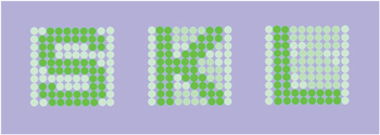
By using a 10 × 10 LC Fresnel lens array, the LCFLD can display letters “S”, “K”, and “L” on the screen as shown in Fig.
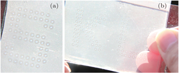
In the experiment, the LC Fresnel lens array was fabricated with the help of photoalignment technology. SD1 (from DIC company, Japan) was utilized as the photoaligning material and coated onto the glass substrates. And the patterned alignment was arranged in the form of specific Fresnel zone lens arrays for displaying letters “S”, “K”, and “L”. Note that SD1 as a photoalignment material in the experiment was optically rewritable, and it could not maintain the alignment under the sunlight or intense LED light for long, therefore it was very important to improve the photostability of SD1 once the patterned alignment was made. The investigation on the SD1 stabilization was in progress and some feasible methods might be worked out soon. The cell gap and the birefringence of the LC cell satisfied the half-wave condition for the green light, and the diffraction efficiency of the polarization-independent LC Fresnel lens approached its theoretical limit ∼ 40%. In principle, the Pacharatnam–Berry (PB) phase liquid crystal lens could substitute for the LC Fresnel lens in this design, but the efficiency would be enhanced by ∼ 10% because the PB phase LC lens was a polarization-dependent element. A 532 nm laser with a divergence angle of 15° and a beam expander were employed as the backlight and an LCFLD with a translucent screen was used to display information. The LCFLD was controlled by two uniform indium-tin oxide (ITO) layers on two respective glass substrates, and it displayed the letter “K” without external electric field as shown in Fig.
By using various types of screens and adjusting the distance between the screen and the LC Fresnel lens array panel, a variety of LCFLDs can be formed. Sunlight was used as the backlight and a uniform holographic screen with transparency of 90% was placed at the focal plane of the LC Fresnel lens array, as shown in Fig.
To increase the contrast ratio and obtain a better performance from the LCFLD, the specific screen should be further designed and improved. The LCFLD is a novel display that simultaneously gets rid off the polarizer and color filter and it can be used as a smart window. It is also an energy-saving technology because it can optionally make use of the sunlight. The fabrication process of the LCFLD is simple, hence it results in low manufacturing costs. This is the starting line for the LCFLD, even though it has some drawbacks at the current stage. The LCFLD is promising and is worth more investigation.
| 1 | |
| 2 | |
| 3 | |
| 4 | |
| 5 | |
| 6 | |
| 7 | |
| 8 | |
| 9 | |
| 10 | |
| 11 |


