† Corresponding author. E-mail:
Project supported by the National Natural Science Foundation of China (Grant No. 51025622).
To deal with the staircase approximation problem in the standard finite-difference time-domain (FDTD) simulation, the two-dimensional boundary condition equations (BCE) method is proposed in this paper. In the BCE method, the standard FDTD algorithm can be used as usual, and the curved surface is treated by adding the boundary condition equations. Thus, while maintaining the simplicity and computational efficiency of the standard FDTD algorithm, the BCE method can solve the staircase approximation problem. The BCE method is validated by analyzing near field and far field scattering properties of the PEC and dielectric cylinders. The results show that the BCE method can maintain a second-order accuracy by eliminating the staircase approximation errors. Moreover, the results of the BCE method show good accuracy for cylinder scattering cases with different permittivities.
The interactions of electromagnetic waves with a curved surface have been widely discussed in many applications, such as material science, optics, photonic crystals, antenna design, and remote sensing.[1–6] In recent decades, a number of numerical methods have been reported for the interactions of electromagnetic waves with curved surfaces, including finite difference methods,[7,8] finite element methods,[9,10] and integral equation methods.[11,12] Among these methods, the finite-difference time-domain method is widely used in computational electrodynamics for easy implementation and accurate results.[13–17] When modeling a curved surface, however, the numerical accuracy may be reduced, because the standard FDTD algorithm uses staircase grids to approximate the material interface.[18] The staircase approximation, as depicted in Fig.
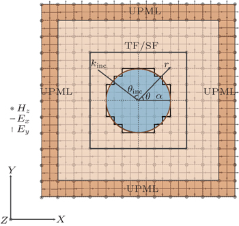 | Fig. 1. Staircase approximation of a circular cylinder in FDTD calculation. Here, UPML means uniaxial perfectly matched layer. TF/SF: total field/scattering field. |
A possible solution to the staircase approximation problem is using non-orthogonal grids or curvilinear coordinates to approximate the curved surface.[20,21] Obviously, while improving the numerical accuracy, these methods would increase the complexity of the algorithm and cause numerical artifacts.[19] A more commonly used method is the conformal FDTD method.[22] However, the numerical stability of the contour-path FDTD method may not be guaranteed, because there are electric nodes whose values are borrowed from neighbor cells.[23] Research is ongoing for the improvements of the contour-path FDTD method based on the numerical instability problems.[23,24]
Another possible way for solving the staircase approximation problem is using the effective permittivity to model the dielectric interface. There are several works presenting different kinds of effective permittivity methods, including the volume average method, a first-neighbor average method, the Maxwell–Garnett method, an inverted Maxwell–Garnett method, and the Bruggeman formula method.[19] The problem of the effective permittivity method resides in the selection of the most suitable effective permittivity value. There have been improvements to the effective permittivity method.[25,26] Among these improvements, the sub-pixel smoothing method shows second-order accuracy by employing the mean permittivity for surface-parallel electric components and the harmonic mean permittivity for surface-perpendicular electric components.[27,28]
A third approach is to simulate the real shape by considering the physical location of curved surfaces.[29,30] These methods show good accuracy and almost need no additional computational cost. However, the complexity of the algorithm would be increased due to the modification of the Yee algorithm. According to the classical electromagnetic theory, material interface boundary condition equations are essential for the scattering problems calculation.[31] Therefore, we utilize the Yee algorithm as usual and treat the surface interface as a kind of interface boundary. The layer of grids across the boundary is calculated by considering the boundary condition equations and physical location of the surface interface. Thus, while maintaining the simplicity and computational efficiency of the Yee scheme, the algorithm can solve the staircase approximation problem.
In this work, the boundary condition equations (BCE) method is utilized to deal with the staircase approximation problem in curved surface scattering. The paper is organized as follows. Firstly, the two-dimensional BCE algorithm is proposed in this paper. Subsequently, the BCE method is validated by analyzing the induced surface current on a PEC circular cylinder. Furthermore, the near field scattering properties of the dielectric circular cylinders are investigated, and the relative errors of different methods are compared. Then, we discuss the far field scattering properties of dielectric cylinders and show the effect of different dielectric permittivities on different methods. Finally, some concluding remarks are derived.
In this section, the BCE method is introduced to solve the staircase approximation problem in curved surface scattering.
The finite difference time domain method is a state-of-the-art method for solving Maxwell's equations in complex geometries.[13] Considering linear, isotropic, non-dispersive, and lossy media, the FDTD method solves Maxwell’s curl equations as follows:[13]


For TE wave incidence, Maxwell’s equations in two-dimensional FDTD can be found in previous publications as[13]


Two-dimensional FDTD equations for TM wave incidence can also be found in previous publications.[13]
The FDTD computation setup is presented in Fig.
Arithmetic mean:[32]

Harmonic mean:[32]

However, these methods still suffer from the drawbacks of staircase approximation. To improve the numerical accuracy, the boundary condition equations on the material interface must be considered. For the curved surface case, we can use the same Yee algorithm as usual and just apply the boundary condition equations on the interface boundary. To calculate the grids across the interface boundary, the physical location of the interface boundary must be considered rigorously.[29]
Figure
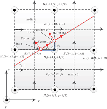 | Fig. 2. Electromagnetic fields configuration for the material interface. Here, ET and EN are the tangential and normal components of the electric field. |
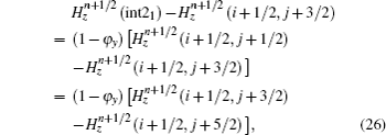
To update Hz(i + 1/2, j + 1/2) in Fig. 


Similarly, the formula of the new 


According to the forward difference approximation with the first-order accuracy, we obtain


Similarly, the formula of 


To calculate 


Then, 


Thus, we derive the formulas of 


Consider the scheme of updating the Ex(i + 1/2, j + 1) field, the electric field point and the nearest two magnetic field points are treated as a group. When an interface passes through the group of points, it separates one magnetic field and the electric field into different media. The configuration can be presented in Fig.
To update Ex(i + 1/2, j + 1) in Fig. 


In the case of a PEC interface, the boundary condition equations are different from that of the dielectric interface. Assuming media 2 in Fig.

To update Ex(i + 1/2, j + 1) in Fig. 



The scheme for updating the Ey(i, j + 1/2) field in Fig. 

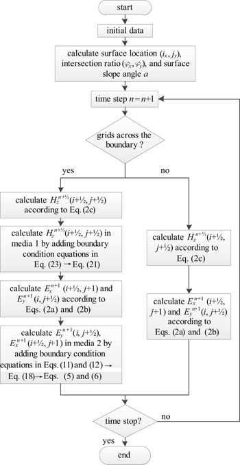
Thus, we have set up the methodology for adding the boundary condition equations in a two-dimensional TE FDTD algorithm. In summary, the flow chart of the BCE method is drawn in Fig.
The BCE method utilizes the standard FDTD algorithm with a second-order accuracy. All the approximations across the boundary are based on the one side difference approximation or non-centered difference approximation. Thus, it is sufficient to guarantee a second-order accuracy globally.[30] In addition, the BCE method can be extended to solve three-dimensional problems. The surface location (i, j, k) and intersection ratio (φx, φy, φz) should be calculated instead of the surface location (i, j) and intersection ratio (φx, φy) in the preprocessing stage, also, matrix R and T must be replaced by a coordinate transform matrix in three dimensions. The boundary condition equations are similar to those of two-dimensional problems.
In this section, analytical and numerical data validations of the BCE method are presented. Comparisons of different methods are made, including the staircase approximation (SA) method, arithmetic mean (AM) method, analytical solution (AS) method, and BCE method. Results from the sub-pixel smoothing (SPS) method are also given for method validation.[27,28]
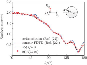
To validate the FDTD algorithm, the induced surface current of a PEC circular cylinder is analyzed. The PEC circular cylinder has a radius of a = 5/ki and is under transverse electric (TE) illumination. Here, ki = 2π/λ is the wave vector. Figure
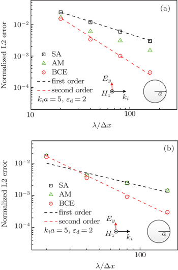
In this part, the near field scattering properties of a kia = 5 dielectric circular cylinder is analyzed. The permittivity and permeability in free space are given as ε0 = 1, μ0 = 1, σ0 = 0, and σm,0 = 0. The material parameters of the dielectric circular cylinder are εd = 2, μd = 1, σd = 0, and σm,d = 0. The incident waves are time-harmonic TE mode fields with an amplitude of |Hin| = 1.0 A/m and transverse magnetic (TM) mode fields with an amplitude of |Ein| = 1.0 V/m. The incident waves have a wavelength of λ = 1 m. The grid size is chosen as λ/160, and the simulation time is chosen to be t = 1.67 × 10⁻⁷ s to make sure that the numerical results are convergent. We use the SA, BCE, and AS methods to calculate a total field region of [–2 : 2] m×[–2 : 2] m. For the infinite cylinder scattering cases, analytical solutions can be derived from previous publications.[33–35]
To compare the local error in the whole computation region, the normalized L2 error for TE wave incidence can be defined as
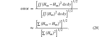
The normalized L2 error for TM wave incidence is similar to that for TE wave incidence.
Figure
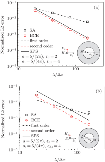
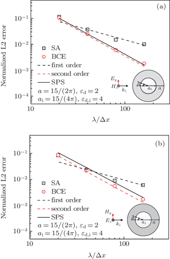
In addition, the BCE method can be used to deal with multilayer object scattering problems. For the multilayer circular cylinder scattering cases, analytical solutions can be derived based on the Mie theory.[36,37] In this part, the near field scattering properties of two double-layer dielectric circular cylinders is analyzed. The radius of the first double-layer circular cylinder is a = 5/(2π) m and ai = 5/(4π) m. The radius of the second double-layer circular cylinder are a = 15/(2π) m and ai = 15/(4π) m. The material parameters of the outer dielectric circular cylinders are εd = 2, μd = 1, σd = 0, and σm,d = 0. The material parameters of the inner dielectric circular cylinders are εd,i = 4, μd = 1, σd,i = 0, and σm,d,i = 0. The incident waves have a wavelength of λ = 1 m. We use the SA, BCE, SPS, and AS methods to calculate a total field region of [–2 : 2] m×[–2 : 2] m.
Figures
To compare the performance of the SA method and BCE method, the far field RCS of a dielectric circular cylinder with a = 0.2λ is analyzed. The permittivity and permeability in free space are given as ε0 = 1, μ0 = 1, σ0 = 0, and σm,0 = 0. The material parameters of the dielectric circular cylinder are εd = 9, μd = 1, σd = 0, and σm,d = 0. The incident waves are time-harmonic TE mode fields with an amplitude of |Hin| = 1.0 A/m and TM mode fields with an amplitude of |Ein| = 1.0 V/m. The incident waves have a wavelength of λ = 1 m. The grid size is chosen as λ/80, and the simulation time is chosen to be t = 1.25 × 10⁻⁸ s to make sure that the numerical results are convergent. We use the SA, BCE, and analytical solution methods to calculate the far field RCS.
Figure
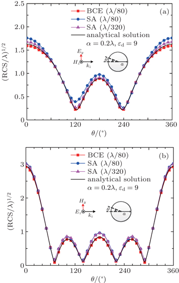 | Fig. 8. Far field RCS comparison (a = 0.2λ, εd = 9). SA and BCE are staircase approximation and boundary condition equations methods. (a) TE wave illumination and (b) TM wave illumination. |
To demonstrate the method capability, the far field RCS of two cylinders with complex geometries are analyzed. The two cylinders are presented in Figs.
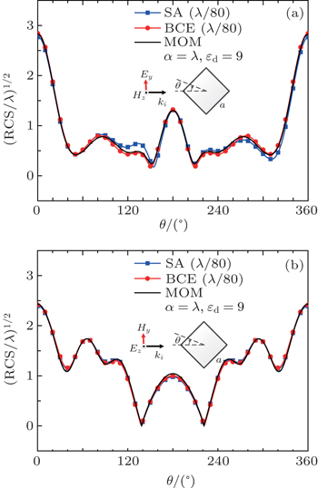 | Fig. 9. Far field RCS comparison (a = λ, εd = 9). SA and BCE are staircase approximation and boundary condition equations methods. (a) TE wave illumination and (b) TM wave illumination. |
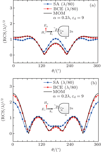 | Fig. 10. Far field RCS comparison (a = 0.2λ, εd = 9). SA and BCE are staircase approximation and boundary condition equations methods. (a) TE wave illumination and (b) TM wave illumination. |
Figures
The BCE method is proposed to deal with the curved surface scattering in the FDTD calculation. In this method, the curved surface interfaces are modeled by adding the boundary condition equations. Thus, the real shapes of a curved surface can be simulated and the staircase approximation errors can be eliminated. To validate the BCE method, various scattering properties are analyzed, including the induced surface current of a PEC circular, and the near field and far field scattering of the dielectric cylinders. The results show that the BCE method can maintain a second-order accuracy by eliminating the staircase approximation error effectively, whereas the SA and AM methods can only achieve a first-order accuracy. The results of the BCE method show better accuracy than that of the SPS method by considering the physical location of curved surfaces according to the surface location and intersection ratio. In addition, the results of the BCE method agree well with those of the analytical solution method for different dielectric contrast cases.
| 1 | |
| 2 | |
| 3 | |
| 4 | |
| 5 | |
| 6 | |
| 7 | |
| 8 | |
| 9 | |
| 10 | |
| 11 | |
| 12 | |
| 13 | |
| 14 | |
| 15 | |
| 16 | |
| 17 | |
| 18 | |
| 19 | |
| 20 | |
| 21 | |
| 22 | |
| 23 | |
| 24 | |
| 25 | |
| 26 | |
| 27 | |
| 28 | |
| 29 | |
| 30 | |
| 31 | |
| 32 | |
| 33 | |
| 34 | |
| 35 | |
| 36 | |
| 37 |


